
3
Source Zone Characterization
One of the goals of this study was to explain the importance of characterization to the effectiveness of source remediation, including a discussion of tools or methods used to delineate sources of organics contamination in the subsurface. The environs of a hazardous waste site described in Chapter 2—that is, the hydrogeologic environment and the distribution of contaminants—are revealed through site characterization. Site characterization is a continuous, dynamic process of building and revising a site conceptual model that captures relevant aspects of a hazardous waste site, including the source zone. The site conceptual model represents current understanding of the site in terms of the relevant subsurface materials and processes, serves as the basis for more sophisticated site characterization, and will ultimately support the evaluation of various remedial alternatives. Because of the inherent scarcity of available data at field sites, the site conceptual model can only provide an approximation to the real world. Indeed, at the early stages of site conceptual model development, it is possible that several realizations will be tenable. However, as more monitoring and other data become available, the various plausible site conceptual models should gradually converge into a single picture encompassing all salient fluid flow and material transport and transformation processes. Site conceptual models are continually refined, possibly using computer models, to address site-specific complexities involving spatial and temporal variations in flow, transport, and transformation processes.
Although it is impossible to prescribe a specific step-by-step source zone characterization process because of differing conditions from site to site, there are four broad categories of information that are critical for characterizing all source zones:
-
Understanding source presence and nature. What are the components of the source, whether a DNAPL or explosive material, and what is the expected behavior of the individual components based on known information?
-
Characterizing hydrogeology. What are the lithology of the subsurface and groundwater flow characteristics as they pertain to the source zone? Are there multiple aquifers at the site, and how are they connected? What are the properties and connectedness of the low permeability layers or zones? Can the flow system be described at the specific site and at a larger scale? Can the groundwater velocity and direction (and the spatial and temporal variation in both) be measured?
-
Determining source zone geometry, distribution, migration, and dissolution rate. Where is the source with respect to lithology? Is it present as pooled DNAPL, distributed as residual saturation, or both? Is it crystalline explosive material, or is it sorbed? What is the current vertical and lateral extent of the source material, and what is the potential for future migration based on the hydrogeologic characteristics of the site? How fast is the source dissolving?
-
Understanding the biogeochemistry. What roles do transport and transformation processes play in attenuating the source zone and the downgradient plume? How will possible remediation strategies affect the geochemical environment (e.g., by releasing other toxic substances, or by adding or removing substances upon which microbial activity and contaminant degradation depend)?
There may be an overall work plan directing that the source characterization activities described above be conducted in a particular order. However, each of the activities is related to the others, and a good deal of iteration between the general categories is not only desirable but critical to the process. Furthermore, iteration between source zone characterization and other site conceptual model building blocks should be employed to constantly reassess site understanding and integrate new data from all facets of the characterization.
This chapter addresses several aspects of source zone characterization, beginning by examining some potential ramifications of inadequate source zone characterization. A subsequent section discusses the four primary categories of information important to source zone characterization and outlines a broad array of characterization methods and tools. General methods for site characterization have been described elsewhere (ITRC, 2003; EPA, 2003a; Thiboutot et al., 2003) and will not be detailed here. Specific source characterization methods for explosives are not well developed and are also not addressed in detail in this chapter. The chapter closes by discussing (1) the importance of source zone characterization to determining cleanup objectives, (2) scale issues, and (3) coping with uncertainty during the process.
A recurring theme in this chapter is that source zone characterization should be carried out in a manner that best informs the entire source remediation process. Decisions regarding the objectives of remediation and the remediation tech-
nologies selected will have a strong impact on the source zone characterization strategy and vice versa. These subjects are addressed in Chapters 4 and 5, respectively, and the reader is encouraged to keep the interrelationship between these three key topics in mind.
KEY PARAMETERS OF SOURCE ZONE CHARACTERIZATION AND THE TOOLS TO MEASURE THEM
The four categories of information important for source zone characterization are (1) the nature and presence of the source material, whether it be a DNAPL or chemical explosives, (2) the hydrogeologic setting, (3) source zone delineation, including geometry, distribution, migration, and dissolution rate in the subsurface, and (4) the biogeochemical environment of the site. These categories of information, and the tools necessary to measure certain parameters, are discussed in detail below.
Because of the variation and complexity of the subsurface environment and the various human activities performed at different sites, no two DNAPL or explosives-contaminated sites are the same. Therefore, there is not a standard suite of tools that can be prescribed for source characterization. Each site must be characterized in a manner that addresses its particular set of constraints and challenges. Before the necessary source zone characterization tools are chosen, it is important that the capabilities and limitations of the tools and the uncertainty of the data generated be generally understood. Many tools are appropriate for both source zone and general site characterization and can provide useful information that spans several of the four categories listed above.
The impact of cost, regulator acceptance, and other nontechnical factors should also be considered in decisions on appropriate characterization tools. For example, drilling and core analysis to assess DNAPL distribution and saturation is an inexpensive method that is accepted by the regulatory community. Partitioning interwell tracer tests (PITT), on the other hand, have been less widely used (primarily for cost reasons), even though they have advantages over drilling and coring in terms of determining the volume of residual DNAPL. Costs and regulatory requirements pertaining to the handling and disposal of investigation-derived wastes can be high for both DNAPLs and explosives.
Safety issues will also vary depending on the source material involved. When performing field characterization of suspected explosives source areas, field teams must be vigilant because of the risk of detonation (EPA, 1993). For example, soils contaminated with ~12 percent to 15 percent TNT or RDX could propagate a detonation after initiation by flame and shock (Kristoff et al., 1987). For this reason, the Army considers explosives in soil at greater than 10 percent to constitute a detonation risk. Thus, geophysical methods are often used to safely get information on site hydrogeology before drilling is commenced on production and training ranges (see Thiboutot et al., 2003).
Table 3-1 summarizes various characterization methods and tools and their applicability for addressing the four categories relevant to source zone characterization. More detailed information about each tool is presented in Table 3-2, including a brief description of the tool and what it measures, the general application of the tool, and the general limitations of the tool for source zone characterization. A variety of methods and tools are presented here including noninvasive characterization approaches ranging from collecting historical information to certain geophysical techniques, invasive sampling tools, methods for laboratory analysis, and tools that represent a combination of the above. The tools found in Tables 3-1 and 3-2 are not equivalent, as some are approaches to removing contaminant samples from the subsurface, some measure specific chemicals either in situ or following sample extraction, some perform both functions, and some do neither. Furthermore, some of the tool categories are much broader than others, and some may overlap slightly. The tables are meant to be inclusive and provide a broad overview of the array of tools and methods often used in source zone characterization.
There are a number of references that provide additional information on the applications and limitations of these techniques. For example, Cohen et al. (1993) and ITRC (2002, 2003) provide details on many of these techniques. NRC (2003)
TABLE 3-1 Various Characterization Methods and Their Potential for Providing Source Zone Information
TABLE 3-2 Summary of Various Methods and Tools and Their Application to Source Zone Characterization
|
Method/Tool |
Tool Description and What Is Measured |
Application/ Relevance to Source Zones |
Limitations |
|
Historical Data |
Information about types and amounts of chemicals used and practices for chemical handling and disposal. Provides |
understanding of DNAPL composition and source location. |
Subsurface solvent migration unknown. Chemical composition changes with time. |
|
Regional Geology |
Information about fractures, sink-holes, springs, and discharge points. |
Used for site conceptual model and determining hydrogeologic setting. |
Site-specific details difficult to infer from this information. |
|
Geophysical Methods |
Methods include: |
|
|
|
|
a) Seismic refraction and reflection. Seismographs measure the subsurface transmission of sound from a point source. |
Provides 3-D stratigraphic map. Useful for defining geologic heterogeneities. |
Not specific for DNAPL detection. |
|
|
b) Electrical resistivity measures bulk electrical resistance during transmission of current between subsurface and ground surface electrodes. |
Used to determine site stratigraphy, water table depth, buried waste, and conductive contaminant plumes. |
Not applicable for DNAPL detection. |
|
|
c) Electrical conductivity measures bulk electrical conductance by recording changes in the magnitude of electromagnetic currents induced in the ground. |
Used for determining lateral stratigraphic variations and the presence of conductive contaminants, buried wastes, and utilities. |
Not applicable for DNAPL detection. |
|
Method/Tool |
Tool Description and What Is Measured |
Application/ Relevance to Source Zones |
Limitations |
|
Geophysical Methods (Continued) |
d) Ground-penetrating radar measures changes in dielectric properties of materials by transmitting high-frequency electromagnetic waves and continuously monitoring their reflection from interfaces between materials with different dielectric properties. |
Used to determine site stratigraphy, and the location of buried wastes and utilities. |
Cannot penetrate clay layers. Not specific for DNAPL. |
|
|
e) Magnetic techniques measure perturbations to the earth’s magnetic field caused by buried ferrous metal objects. |
Used for finding steel drums at landfill sites. |
Limited to ferrous metal detection. |
|
Direct Push |
Direct push techniques are used both for retrieving subsurface samples and for performing in situ analyses of physical and chemical parameters. Two major techniques include cone penetrometer (CPT) and rotary hammer methods. They are similar in their principles of operation but differ in scale and in some of their applications. CPT systems, which are used mainly for in situ measurements, make use of sensors that measure soil and sediment resistance. CPT is often used in conjunction with aqueous phase (drive point) sampling and probes [e.g., laser-induced fluorescence, neutron probe, membrane interface probe (MIP)]. |
Used for gaining information about the physical properties of soils, stratigraphy, depth to the water table, pore pressure, and hydraulic conductivity. Extracted aqueous phase samples may be analyzed quantitatively ex situ. MIP provides semiquantitative subsurface aqueous volatile organic compound (VOC) concentration data, while laser-induced fluorescence detects fluorescing compounds. |
Direct push techniques are generally quicker and more mobile than traditional drill rigs, and there is no drilling waste. However, they are not applicable in bedrock, boulders, and tight clays. They are limited to unconsolidated aquifers and to depths of less than 100 ft (30 m). They require calibration with borehole data for accurate interpretation of stratigraphy. Chlorinated solvents do not fluoresce. |
|
Method/Tool |
Tool Description and What Is Measured |
Application/ Relevance to Source Zones |
Limitations |
|
Core Retrieval and Analysis |
A variety of drilling techniques (rotosonic technologies, flight augers, hollowstem augers, rotary drilling, and cable tool drilling) coupled with different sampling tubes (hollow stem or piston tubes) can be used to collect cores from unconsolidated or consolidated media. |
Provides direct information regarding porous media, geology, and stratigraphy. The samples can be tested for contaminants or other biogeochemical species. |
Provides a point measurement of spatially variable parameters. Collection methods may alter the physical–chemical properties of the core. Expensive at radioactive sites. |
|
Downhole Methods |
a) Downhole video (e.g., GeoVIS) illuminates soil in contact with a sapphire window and images it with a miniature color camera. |
Provides visual imaging of borehole. NAPL possibly visible as |
Conditions for effectiveness not well defined. |
|
|
b) Downhole flow metering impeller or thermal flowmeters measure groundwater inflow rate. |
Identifies zones of preferential flow. |
Calibration with other flow metering techniques necessary to ensure accuracy. |
|
|
c) Caliper logging tool follows borehole wall and measures hole diameter. |
Identifies cavities or fractures in borehole. |
Provides only point measurements. |
|
|
d) Specific conductance probe determines fluid conductivity with depth. |
Can identify inflow zones and contamination zones. |
Limited to contaminants that change fluid conductivity (i.e., not DNAPL). |
|
|
e) Natural gamma logging measures emissions from isotopes preferentially sorbed in clay and shale layers. |
Reveals presence of shale or clay layers. |
|
|
|
f) Gamma-gamma log measures media response to gamma radiation. discrete globules. |
Provides information about formation density. |
|
|
Method/Tool |
Tool Description and What Is Measured |
Application/ Relevance to Source Zones |
Limitations |
|
Downhole Methods (Continued) |
g) Neutron logging measures media response to neutron radiation. |
Measures moisture content and porosity. |
|
|
|
h) Electrical resistance or conductance devices measure these properties of formation fluids and media. |
Enables identification of lithology, stratigraphy, or high ionic strength-contaminated water. |
Typically used in conjunction with core analysis or other borehole data. |
|
Piezometers |
Primarily used to determine pressure head spatially and temporally on the site. |
Used for potentiometric mapping to understand groundwater flow. Screen length is important. |
May not provide the detail needed within the source zone. Because head distribution changes over time, sampling can be required over an extended time. |
|
Pump Tests |
Pumping groundwater and then monitoring the drawdown cone and rebound can be used to estimate permeability, hydraulic conductivity, the radius of influence, and flow boundaries. Standard tracer tests (e.g., bromide or iodide) are frequently used during pumping to confirm flow models and optimize flow. |
This information is necessary for site conceptual model development and remedial activities. |
Provides a spatially averaged estimate. Not specific for locating preferential paths or highly permeable zones. |
|
Groundwater Analysis |
Discrete water samples can be collected with various pumps, bailers, or samplers and then analyzed for different contaminants and groundwater constituents of interest. Multilevel sampling allows water sampling at various depths within a single well. |
Helps delineate source areas on site and document preremediation conditions in order to later evaluate whether remedial objectives have been met. |
Good understanding of groundwater flow, biogeochemistry, and DNAPL composition is needed for proper interpretation. |
|
Method/Tool |
Tool Description and What Is Measured |
Application/ Relevance to Source Zones |
Limitations |
|
Solid (Matrix) Characterization |
Includes analysis of organic matter content, percent clay and clay type, silt content, mineral composition, and wetting behavior. |
Improves understanding of the source zone and the impact of the subsurface environment on remedial actions (e.g., oxidation). |
Difficult to quantitatively relate bulk soil measurements to contaminant behavior. |
|
Microbial Analyses |
Microbial community composition and functional potential can be measured for extracted subsurface samples using a combination of molecular techniques and tools based upon conventional culturing and microcosm approaches. |
Identifies organisms and genes that are present within the subsurface community to evaluate potential activity and quantify functional activity associated with the active microbial population. |
Difficult to extrapolate laboratory activity measurements and rates to in situ field activity. |
|
Soil Vapor Analysis |
Soil probes or passive soil-gas collectors are used to withdraw soil gas. A variety of analytical techniques are used to measure the actual contaminants (e.g., GC-MS). |
May be used for indicating “hot spots” of contamination. |
Provides point measurements. Understanding of partitioning and NAPL composition is necessary for interpretation. Reflects DNAPL distribution in the vadose zone only. |
|
DNAPL Analysis |
A variety of analytical techniques are used to determine DNAPL chemical composition (e.g., GC-MS) and chemical-physical properties such as viscosity (e.g., viscometer), interfacial tension (e.g., pendant drop method), and density (e.g., densitometer). |
Used to better interpret groundwater and vapor sample measurements and to enhance site conceptual model (SCM) and modeling efforts. |
DNAPL samples are difficult to obtain and may be variable across the site and with time. |
|
Method/Tool |
Tool Description and What Is Measured |
Application/ Relevance to Source Zones |
Limitations |
|
Partitioning Tracer Tests |
Hydrophobic chemicals such as higher-weight alcohols (partitioning tracer) are injected through a contaminated zone with a conservative tracer. The reactive tracers partition into DNAPL and experience a delay in breakthrough as compared to the conservative tracer. The retardation and partition coefficients are used to determine NAPL saturation. |
Provides in situ estimates of DNAPL saturation. Can provide information on DNAPL distribution when coupled with multilevel sampling. |
Expensive. Limited to media with sufficiently high permeability. |
|
Ribbon NAPL Samplers |
Material is placed on a core or in bore holes that reacts with NAPL. Flexible Liner Underground Technologies Everting (FLUTe) is an example. |
Provides continuous record of DNAPL distribution in borehole. |
Only indicates presence (not amount) of DNAPL. Not proven to be responsive in all cases; thus, negative results are not conclusive. Time in borehole may be important. |
|
Hydrophobic Dyes (such as Sudan IV) |
Hydrophobic dye shake test for detecting DNAPL in soil samples. |
Onsite screening tool for locating DNAPL. |
Can only indicate presence (not amount) of DNAPL. |
provides information on various sensors and analytical techniques and their appropriate applications. An expert panel report to the U.S. Environmental Protection Agency (EPA) on DNAPL source depletion presents a summary of characterization tools (EPA, 2003a), Kram et al. (2001, 2002) provide a comparison of various analytical techniques with cone penetrometers, and Griffin and Watson (2002) provide a comparison of field techniques to confirm DNAPLs. A large amount of information on sampling technology can be obtained from the Department of Energy’s (DOE) Environmental Management Science Program, EPA’s Technology Innovation Office (http://fate.clu-in.org), and EPA’s Environmental
Technology Verification program (http://www.epa.gov/etv). Sampling in fractured rocks is discussed in Shapiro (2002). Thiboutot et al. (2003) provides extensive information on characterization of explosives soil sites, primarily on military training and testing ranges, including the risks of detonation and appropriate sampling strategies and chemical analysis methods.
Source Presence and Nature
Before extensive source zone characterization methods are undertaken, an effort should be made to first determine the nature of the source. Determining the composition of the DNAPL or explosive material is useful for a variety of site management activities. Knowing the components of the source and being able to predict the expected behavior of the individual components based on known information is important for performing risk assessment and surmising appropriate remedial actions for the site. For DNAPLs, the physical–chemical properties such as solubility, density, specific gravity, viscosity, interfacial tension, wettability, contact angle, and the tendency to partition between sediment and water should be determined if possible (see Cohen et al., 1993, for analytical methods relevant to characterizing DNAPLs). The concentrations analyzed in sediment and water can be related to health-based standards, and estimates of the human and ecosystem exposure to the contaminants can be predicted. This information is necessary to guide subsequent phases of site characterization.
Kram et al. (2001) provide an excellent summary of field techniques and information for determining DNAPL source material information based both on direct and indirect evidence. Direct detection of a DNAPL source can be accomplished via various analyses of soil, rock, or water cores and samples. These range from such simple techniques as visual observation (such as with downhole video) and soil shake tests with hydrophobic dyes, to measurements of UV fluorescence in situ or within extracted samples or cores, or to ribbon NAPL samplers used either ex situ to test extracted cores or in situ within boreholes. These various techniques are generally used to determine the presence or absence of DNAPL and not necessarily total mass or chemical composition.
Understanding the presence and nature of the source material can be a challenge at sites where a DNAPL or solid phase explosive sample cannot be isolated from the source zone. In such cases, indirect methods such as measuring high aqueous or vapor contaminant concentrations relative to saturated aqueous or vapor concentrations, or measuring high contaminant concentrations in soil cores, are used for inferring the presence of a separate phase (see Box 3-1 for an example relevant to chemical explosives). For example, aqueous concentrations in excess of 1 percent of DNAPL solubility (Mackay et al., 1991; Cohen et al., 1993) or soil concentrations greater than about 10,000 mg/kg (EPA, 1992) are generally considered to be indicative of DNAPL presence. Caution should be taken when using this technique to infer DNAPL presence because of the highly
|
BOX 3-1 One method to infer the potential presence of a separate solid phase is through evaluation of phase partitioning equilibria (Jury et al., 1991; Phelan and Barnett, 2001). Jury et al. (1991) shows that the total concentration (CT) of a chemical constituent in soil can be partitioned among the soil-sorbed, soil-water, and soil-air phases: where ρb is the soil bulk density (g/cm3), Kd is the linear soil-water partitioning coefficient (cm3/g), Cl is the concentration in the soil water (g/cm3), θ is the volumetric soil moisture content (cm3/cm3), a is the air-filled porosity (cm3/cm3), and KH is the Henry’s constant (unitless). At a specific temperature, the maximum concentration of a solute in water is specified by the solubility limit. If the temperature dependent solubility limit is used with estimates for ρb, Kd, θ, a, and KH in the equation above, CT is the maximum total concentration, as determined from a field soil sample, before a separate chemical solid phase must appear. Figure 3-1 is the result of an analysis that shows the maximum total soil concentrations of RDX (a solid phase energetic material) that can be partitioned in soil before a separate solid phase must exist. At 20°C, the maximum solubility of RDX in water is about 45 mg/L. Due to the low vapor pressure and air-water partitioning coefficient (KH), the soil-water partitioning coefficient (Kd) is the principal factor influencing the maximum total soil residue. Figure 3-1 shows that total soil residue concentrations above 30 to 70 µg/g (sum of liquid, sorbed to soil, and vapor phases) indicate the potential presence of solid phase material in the soil system. The lower the soil-water partitioning coefficient (Kd), the lower the maximum total soil residue because of the smaller sorption capacity of the soil. This case is for nearly saturated soil (Sl = 99 percent, where Sl is defined as the volumetric soil moisture content θ divided by the soil porosity). |
heterogeneous distribution of DNAPL. Aqueous concentrations may vary by an order of magnitude over small vertical and horizontal distances, such that sampling from specific depth intervals (using multilevel monitor wells, drive point sampling at specific depths, or short well screens) may be advisable for providing more resolution on potential sources than conventional monitor wells with large screened intervals. In addition, the solubility of individual components in a multicomponent DNAPL is lower than that of pure compounds. Empirical evidence clearly indicates that the lack of observations above these numerical limits does not preclude the presence of DNAPL (Frind et al., 1999; Dela Barre et al., 2002). It should be kept in mind that groundwater and soil sampling provide general composition information only for the soluble components of the source material
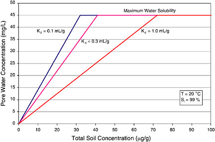 FIGURE 3-1 Effect of soil–water partitioning coefficient (Kd ) on maximum soil residue for RDX. SOURCE: Phelan et al. (2003). |
(unless one is fortunate enough to collect a core sample that contains DNAPL in its pores, something that is unusual due to the highly inhomogeneous DNAPL distribution). Furthermore, solids can interfere with the extractability of certain components. Historical records may be able to provide some information on the age and identity of the compounds and how they were used on the site. Yet, short of collecting actual chemical samples such as a DNAPL sample, it may not be possible to fully understand the nature of the source material (in terms of the key physical and chemical parameters mentioned above).
Table 3-3 lists the likelihood of a source zone being present at a site, given the occurrence of certain events. For example, if there was a known or probable historic release of a DNAPL, then there is high certainty that there is a source.
TABLE 3-3 The Degree of Uncertainty Regarding the Presence of a Source Zone at a Site Based on the Occurrence of Various Events.
|
Event |
DNAPL Source |
|
Known or probable historical release of DNAPL |
High certainty |
|
Process or waste practice suggests probable DNAPL release |
High certainty |
|
DNAPL visually detected in subsurface, monitoring wells, etc. |
High certainty |
|
Chemical analyses indicate DNAPL presence ( ≥ saturation) |
High certainty |
|
DNAPL chemicals used in appreciable quantities at site |
Likely; some uncertainty |
|
Chemical analysis suggests possible source zone |
Likely, some uncertainty |
|
SOURCE: Modified from Cohen et al. (1993) diagram, Figure 7-1. |
|
The wide range of chemicals used and disposal methods practiced can result in great variability in the chemical mass and composition across the site. Therefore, finding and analyzing one DNAPL sample may not provide a representative assessment of the overall contamination. It is also possible that the source area is not necessarily stable over time. Source material can change as the more soluble, biodegradable, or volatile components are removed, altering the material’s composition and, in turn, affecting its chemical and physical properties. In addition, the source itself, as in the case of DNAPLs, can continue to move due to natural changes in the subsurface and to various characterization and remediation activities performed at the site.
Identification of explosives as subsurface source material will most likely occur via chemical analysis of soil samples. Field-screening methods are an ideal method to determine high concentrations during field campaigns. These methods require extraction of a 2- to 20-g soil sample with acetone or methanol. Then, either a colorimetric or immunoassay detection method is used for obtaining quantitative or semiquantitative results (Crockett et al., 1998). These methods are applicable to TNT, DNT, RDX, and HMX as well as to other explosive compounds, with detection limits for most methods at ~1 ppm. When employing these methods, users must be aware of possible interferences with the colorimetric methods and of cross-reactivity for immunoassay methods. Other emerging chromatography-based field methods may provide more quantitative results (Hewitt and Jenkins, 1999).
Characterizing the Hydrogeology
An accurate depiction of the subsurface and its flow characteristics is critical to the overall site conceptual model and necessary for developing successful remediation strategies. The primary difficulty in characterizing the subsurface is in determining the heterogeneity of the geologic material and understanding how this affects groundwater and contaminant transport. Nonetheless, it is often
possible to develop a general description of a site, including the surface topography, the regional geology such as whether the subsurface material is consolidated or unconsolidated, and the regional groundwater patterns (e.g., flow from areas of recharge—rainfall, surface impoundments, or ponds—to areas of discharge—surface water features or pumping wells), without large amounts of site-specific data.
Characterization of subsurface hydrogeology involves a variety of hydraulic and tracer tests as well as detailed hydrostratigraphic determination. Data pertaining to lithology from soil borings and hydraulic head distributions will aid in the development of a more detailed picture of the site layering in terms of relatively permeable and impermeable units, as well as groundwater flow direction. When and if sufficient data are collected, a flow model can be useful to describe water movement through permeable media and around impermeable media to discharge points. In fractured rock systems, an understanding of the flow system is necessary for understanding where the DNAPL has migrated or where it has the potential to migrate.
Determining permeability and effective porosity can be difficult at the scale that is needed for accurately portraying flow at a given site. In heterogeneous aquifers, permeability can range over 13 orders of magnitude. Pump tests are often used for determining permeability in the field; however, they provide a spatially averaged value that cannot yield insight into the heterogeneity often observed in Type III and V settings, which are characterized by low-permeability zones. In some fractured rock aquifers, such as karst aquifers, obtaining adequate data on the hydraulic properties and determining flow paths are even more difficult, if not impossible. Understanding the flow system and being able to determine groundwater velocities are important in order for mass flux reduction to be used as a metric for source remediation (see Chapter 4).
A number of noninvasive characterization techniques developed over the years for delineating subsurface heterogeneities and anomalies are useful for source zone geologic characterization (although they have little applicability to locating sources and defining their distribution within the subsurface). Geological mapping and interpretation from outcrops and other geomorphic features can provide information on aquifer characteristics and possible zones of infiltration near a source zone. Other techniques (see Table 3-2), such as seismic refraction and reflection methods, electrical resistivity, electrical conductivity, ground-penetrating radar (GPR), and magnetic techniques, involve the input of some type of energy into the subsurface and an appropriate detector that captures the transmitted energy. For example, electrical resistivity involves the transmission of a current between the subsurface and implanted electrodes and measurement of the bulk electrical resistance of the media though which the current passes.
The successful application of noninvasive technologies is often dependent on the field experience of the user as well as on a lack of interference from structures and power lines. The latter can be very difficult to ensure in a manufac-
turing setting or on a site where there is significant historic activity such as filling. Generally, the user must have detailed site knowledge or must independently verify the results with other techniques. Data quality for noninvasive techniques can be very good, but the data are typically calibrated with coring data. More detailed information on such characterization tools can be found in Cohen et al. (1993) and ITRC (2002).
Beyond noninvasive tools, direct push techniques are widely used for characterizing site and source zone hydrogeology. As the name implies, rods equipped with probes, samplers, or other tools are directly pushed into the subsurface using a hydraulic ram, hammer, or vibratory method. Cone penetrometers (CPT) typically use a hydraulic ram for pushing the tool string into the ground, while other drive point methods often use a rotary hammer. Drive point methods are used for conducting continuous and single-point groundwater sampling, for piezometer and monitoring well installation, and for vapor sampling. Cone penetrometers outfitted with a sensor in the cone tip can measure lithostatic pressure, hydrostatic pressure, electrical resistivity, and pore pressure, and they can provide centimeter scale vertical resolution of lithology. In addition, numerous analytical methods have been developed for use within the cone. These include fluorescence spectroscopy, Raman spectroscopy, and UV absorption, which can aid in determining contaminant presence and concentration (see Kram et al., 2001, 2002). Since direct push methods are generally less expensive and less intrusive than conventional drill-based technologies, they are increasingly used whenever site conditions allow (direct push tools cannot penetrate bedrock and may be refused by cobbles or very dense layers).
Downhole methods are increasingly useful for characterizing source zone hydrogeology. Typically used in conjunction with other characterization tools such as soil cores, downhole methods can provide information about stratigraphy, formation density, porosity, fractures, flow paths, and moisture content, depending on the method used. For example, various downhole imaging techniques can provide information about the location of fractures and their orientations, if the fractures intersect the boreholes. It should be noted that the fracture density has little correlation with permeability within a fractured rock aquifer (Paillet, 1998). Therefore, fracture connections in such settings are generally elucidated using conventional aquifer tests with hydraulic stress being applied to a single centrally located borehole and with drawdown being measured in observation boreholes (Tiedeman and Hsieh, 2001). Because most hydraulic testing produces large quantities of contaminated water for disposal and may cause spreading of contaminants, these methods should not be used in source zones without a good understanding of the site. Methods that produce less water, such as cross-borehole flowmeter pulse tests that use short stress times, may be useful for defining subsurface connections between discrete fractures (Williams and Paillet, 2002).
Source Zone Delineation
Source zone delineation refers to determining the location of a source in the subsurface (both horizontally and vertically), its strength,1 and how it moves among and between phases. For example, is the DNAPL pooled at the bedrock, is it pooled at the top of a confining layer in a multilayer sequence of high- and low-permeable units, is it distributed in sediment, is it locally above residual saturation or primarily at or below residual saturation? Without this knowledge, there will be considerable uncertainty about the effectiveness of the chosen remedy and the time required to meet cleanup goals.
An important first step in delineating a source zone is to gather and analyze historical chemical usage and disposal information about the site. Information that can suggest where to look for DNAPLs or explosives is valuable and can save time and money during the remediation process. Hydrogeologic information from previous or ongoing investigations, either on a site scale or a regional scale, can provide valuable information on possible vertical and horizontal flow paths. However, in some cases, such as complex sites that have multiple interconnected layers and fractured bedrock, such information can be difficult to obtain.
Source delineation is most commonly accomplished by analyzing sediment cores, by measuring dissolved concentrations of specific compounds and, in rare cases where possible, by analyzing the free product found in wells or cores. Obtaining soil and rock cores and dissolved contaminant concentrations is generally accomplished using invasive technologies such as core retrieval via drilling and direct push techniques, as previously described. It should be noted that there is a real danger of cross-connecting water-bearing zones when using drilling techniques. Collecting soil cores allows visual and chemical characterization of the source area, and constructing wells allows the application of a variety of pumping-based assessment techniques. In both cases, data are needed in three dimensions to map the source and its dissolved constituents. Because DNAPL distribution may be extremely heterogeneous on a scale of tens of centimeters vertically and a few meters horizontally, cores would have to be taken and analyzed on a similar scale in order to construct a detailed map of DNAPL distribution. However such detailed characterization is generally unnecessary. As mentioned earlier, ribbon NAPL samplers and hydrophobic dyes can provide onsite detection of DNAPLs within the cores or the borehole itself.
Partitioning interwell tracer tests (PITT) offer a method for estimating mass and distribution of the DNAPL over volumes much larger than is possible with soil sampling. This method has been used at more than 50 DNAPL sites with
good success (Jin et al., 1997; Annable et al., 1998; Mariner et al., 1999; Londergan et al., 2000; Rao et al., 2000; Kram et al., 2001, 2002; Meinardus et al., 2002; Jayanti, 2003). Meinardus et al. (2002) reported one of the most complete comparisons ever made between DNAPL volumes measured by a PITT and by hundreds of soil samples from cores; the total DNAPL volume from both methods was in excellent agreement despite significant heterogeneity at the site. The advances in field analytical techniques can shorten the time of analysis and augment laboratory analyses. In addition, the use of multilevel samplers during the PITT can provide better estimates of the spatial distribution of the DNAPL. The technique relies on sufficient contact between partitioning tracers swept through the source zone and the resident DNAPL. The presence of large heterogeneities and a highly variable DNAPL distribution can affect this contact and greatly reduce the accuracy of the test. The application of PITT to complex sites, therefore, may require special design methods such as hydraulic control wells to confine the tracer both laterally and vertically to the source zone. Jayanti (2003) recently analyzed the impact of heterogeneities under a wide range of field conditions.
It is particularly difficult to locate source zones in fractured rock aquifers. Collecting water samples for chemical analysis in fractured rocks can yield highly variable results depending on the aquifer properties—the transmissivity, storativity, and hydraulic head of fractures intersecting the borehole. In situations where it is important to characterize the spatial variability of the groundwater chemistry in a bedrock aquifer, it is advantageous to collect water samples from a discrete interval that hydraulically isolates, with packers or liners, a single fracture or group of closely spaced fractures in the boreholes. In situations where water samples cannot be taken from hydraulically isolated intervals and where water samples are collected from an open borehole, the effect of the water volume in the borehole must be considered in the design of the collection system (Shapiro, 2002).
Although sources can be delineated by monitoring contaminant concentrations at sampling points over time, measurements of contaminant mass flux (the amount of contaminant mass migrating through a cross section of the aquifer orthogonal to groundwater flow within a given time) are increasingly being considered as a more accurate way to determine the effectiveness of remediation (see Chapter 4, Feenstra et al., 1996). To calculate flux, it is necessary to have a good understanding of the flow system and the vertical distribution of concentrations of the source components in at least one transverse transect of the plume prior to commencing remediation. Although the documentation is limited, methods for measuring mass flux are becoming more common in the literature (as described in Box 3-2).
|
BOX 3-2 Determination of the mass flux of a contaminant has been proposed as a metric to assess the progress of DNAPL source remediation (Feenstra et al., 1996; Einarson and Mackay, 2001; API, 2003; EPA, 2003a). The mass flux is the amount of contaminant migrating though a cross-sectional plane that is perpendicular to the direction of groundwater flow. It is expressed as the mass of contaminant moving across a surface per unit area per unit time. In actual use in groundwater field studies, mass discharge (mass per unit time) is determined rather than mass flux, and it is assumed that the area covers the entire plume width. One method to determine mass flux at a specific location is from contaminant concentration data in a cross-sectional area and specific discharge. Because the contaminant concentration and groundwater discharge vary within a cross section, the mass flux can be estimated in small zones and summed to obtain the total flux. The accuracy of the measurement is related to the sample point density and the determination of hydraulic properties of the aquifer. At complex sites this information is difficult to obtain. Another method for determining mass flux is the use of aquifer tests in a downgradient transect of wells and measurement of the mass of contaminant pumped (Bockelmann et al., 2001). If the downgradient wells capture the entire contaminant plume, the mass flux can be calculated from the contaminant concentration and the pumping rate. In many cases the entire plume is not captured, and the method requires knowledge of the pumping well rate, the contaminant data, and other necessary data for use in a flow-and-transport model. All of these requirements have considerable uncertainty. Another concern in using this method is whether pumping will cause additional spreading of the contaminants and the fact that large quantities of water are produced. A third method, still in the development stage, is to measure mass flux by the use of a sorptive permeable medium that is placed either in a borehole or monitoring well to intercept contaminated groundwater. The medium is spiked with a tracer. By quantifying the mass of tracer released and contaminant sorbed, the groundwater velocity and contaminant mass flux can be calculated (Hatfield et al., 2002). This requires knowledge of the partitioning characteristics of the medium and of the contaminants. Although this method may be easier to implement because it requires less quantitative information about the flow system, a disadvantage is that measurements are made at specific points, and some flow paths may not be intersected. The use of sorptive permeable media has yet to be field tested. All of these methods are experimental at present. The reported applications are primarily for site evaluation of natural attenuation and at sites where the contaminants are petroleum hydrocarbons or methyltertbutylether (MTBE), rather than DNAPLs (Borden et al., 1997). Yet, the measurement of mass flux holds promise as a more robust method of quantifying the mass of contaminant loss in cases where information on the groundwater flow system, including hydraulic conductivity and hydraulic gradient, can be obtained. |
Biogeochemical Environment of the Site
Some source remediation technologies can greatly change the redox conditions and the resulting water chemistry and biological activity near the source area and in the downgradient plume. For example, certain treatments, such as use of potassium permanganate, can inhibit microbial populations and stop natural biodegradation processes that were occurring. Other agents, such as surfactants, may actually increase microbial activity by providing a carbon source. Conversely, certain biogeochemical conditions can limit the effectiveness of in situ remediation. For example, where there are high concentrations of organic material in the aquifer, larger amounts of oxidants will be required to ensure reaction with the organic contaminants of interest. To better understand and predict these phenomena, an evaluation of the site geochemistry is essential.
Knowledge of the water chemistry and microbial activity within source zones should be gained prior to commencing a remediation action, particularly when remedies that involve microbial or abiotic chemical transformation are being considered. For example, what minerals are dissolving or precipitating, and what trace elements could be released if the water chemistry changes? It is well known that many trace elements are redox-sensitive and migrate in solution along the hydraulic gradient under certain conditions. An assessment can be made about the potential rates of natural bioremediation and possible enhanced bioremediation by examining the indigenous microbial population in the water/sediment (NRC, 2000; Witt et al., 2002); determining the nature and abundance of electron acceptors in the water, such as oxygen, nitrate, and sulfate (Chapelle et al., 1995; McGuire et al., 2000); determining the amount of extractable iron on the sediments (Bekins et al., 2001); and examining the potential for dissimilatory metal reduction (Lovley and Anderson, 2000).
Both conventional enrichment/isolation-based techniques as well as genetic-based molecular techniques can be used to analyze the microbial community and to evaluate its functional potential. For example, microcosm data can be combined with quantitative polymerase chain reaction (PCR) to evaluate and quantify the presence of Dehalococcoides species at a site and confirm its functional potential (Hendrickson et al., 2002; Lendvay et al., 2003). However, care must be taken when extrapolating laboratory results on microbial activity to natural environments since it is virtually impossible to entirely replicate field conditions in laboratory studies.
Source Characterization at Hydrogeologically Complex Sites
Not all of the characterization tools discussed above are applicable or appropriate in all hydrogeologic settings. Most of the tools have been developed and utilized at sites with porous media (particularly unconsolidated granular geologic environments), and thus do not apply to hydrogeologic settings IV and V or karst
(see Chapter 2). Thus, sites that exhibit a range of hydrogeologic conditions (such as the site described in Figure 2-16) require a range of tools in order for source zone characterization to be carried out. A particular problem is that the tools available for use in fractured rock systems often provide limited (i.e., point-specific) information because of the high degree of spatial variability at these sites. Consider, for example, karst systems, which arise from a combination of water-soluble carbonate rock and a well-developed secondary porosity. The structure of the rock (e.g., the bedding planes, joints, faults, and fractures) forms the basis for the creation of the network of interconnected openings common in karst systems. These openings may include large conduits and are often capable of transporting water (and contaminants) rapidly throughout the site. In such settings, it can be extremely difficult to determine where the source is located and which fractures are hydraulically connected. Innovative approaches such as using tomography to determine which fractures are connected are still in a research stage. Thus, source zones in karst and fractured systems create extreme characterization and remediation challenges, as exemplified by the case study in Box 3-3.
Summary on Characterization Tools
Although it is impossible to prescribe exactly what tools should be used to characterize source zones given their site-specific nature, a typical scenario representing the state of the art can be outlined that utilizes some of the tools described above. Because migration of DNAPL (and hence DNAPL distribution) is to a large extent controlled by permeability (in that low permeability layers exclude DNAPL, while high permeability layers channel it), hydrogeologic characterization is an essential first step during source zone characterization. A combination of historical chemical-use data and analyses of water samples is then used to determine likely areas of DNAPL occurrence. Analyses of core samples from drilling or of samples from direct push or down hole analytical tools can then be used to define the source zone. Due to the extremely heterogeneous distribution of DNAPL, the probability of a core or a push intersecting a small DNAPL source is low; thus, conclusive evidence of DNAPL occurrence is not always found. If deemed necessary, a PITT can be used to confirm the amount of DNAPL present. In general, the objectives of the remediation plan will help determine the level of characterization effort required. This effort will also be constrained by the physical characteristics of the site (i.e., consolidated vs. unconsolidated, fractured vs. nonfractured), since they control how difficult it will be to obtain the required data.
It should be noted that characterization data are collected from a wide range of scales; for example, hydraulic conductivity may be determined from pump tests that average a volume of hundreds of cubic meters or from core samples that average a few cubic centimeters. Furthermore, multiple methods are typically used to measure the same parameter, and making comparisons between the results
|
BOX 3-3 The Redstone Arsenal is a 38,000-acre facility (15,378 hectares) immediately adjacent to Huntsville, Alabama. The underlying geology is a well-developed, mantled intricate network of karst conduits with an ultimate discharge to the Tennessee River to the south. The facility has been in operation since 1941 primarily for rocket propellant research and development. In the mid 1980s to 1996, five solvent degreaser facilities in operation within Operable Unit 10 (OU-10) used TCE and later 1,1,1-TCA. The main contaminants in the groundwater in this area include TCE and perchlorate. The overburden and karstic upper bedrock are intimately interconnected in this area to form a single aquifer with a prevailing upward hydraulic gradient. A sitewide hydrogeologic investigation of the karst system (Phase I) was performed with the following objectives: establish the significance of karst on groundwater flow and contaminant transport, delineate karst watersheds in order to define potential source–receptor flow paths, identify optimal surface and groundwater monitoring locations for long-term monitoring and possible remediation performance assessment, develop a sitewide conceptual model to support decision making, and evaluate the existing perimeter monitoring well network. The actions and outcomes of this investigation are summarized in the following table.
|
|
Source Delineation: Additional characterization at OU-10 was performed with the purpose of trying to identify and characterize DNAPL in the subsurface, including its lateral and vertical extent and mass. Understanding the subsurface stratification was also attempted, as this would aid in developing a source zone conceptual model. Actions and outcomes related to these objectives are shown in the table below.
|
|
Additional activities, including dye tracers, long-term pump tests in the deep bedrock, and natural attenuation assessment, are planned for the source area in OU-10. This is an interesting example of the difficulty of defining the source at complex sites, since even after doing numerous studies, the actual source area is still in doubt. The success of any source remediation would be jeopardized without a better understanding of the source zone. |
is not necessarily simple. For example, aqueous concentrations may be determined in a monitor well screened over several meters, from a drive point well screened over 30 centimeters, or from a fluorescence tool on a direct push unit which measures concentrations over a few square centimeters. Analyses may be from labs using standard methods, from field screening kits, or from downhole tools. In every case both the scale of measurement and the method of analysis will affect the results. In developing the site conceptual model, care must be taken to reconcile the diverse data sets produced by different methods and labs and at different scales.
APPROACH TO SOURCE ZONE CHARACTERIZATION
Gaining an understanding of the complexity of a site through source zone characterization before engaging in expensive remediation technologies can save resources and help to define reasonable cleanup goals. Beyond the four primary types of source characterization information and the associated tools mentioned above, there are other factors site managers should consider during source characterization, as discussed below. Additional issues faced when managing the source characterization process include how to determine what level of characterization is sufficient, the impact of scale, and how to estimate and manage uncertainty. This section also discusses the need for iterative feedback between source characterization information and the selection both of objectives and technologies for source remediation, a topic further developed in Chapter 6 in the context of a decision framework for source remediation.
Source Zone Characterization Should Reflect Remediation Decisions
The goal of source zone characterization is to provide the basis for decisions on remediation. Once a source is determined to be present, a series of decisions will arise in developing a remediation strategy, each of which will require specific characterization information. The major decisions include defining remediation
objectives, determining if there are one or more potentially effective technologies capable of meeting the chosen objectives, selecting the best technology for the site, designing a remediation project, and evaluating the effectiveness of remediation. Each of these decisions is described in detail in the following chapters (objectives in Chapter 4, remedial technologies in Chapter 5, and the decision process in Chapter 6). Because different technologies and different objectives require different types of characterization, source characterization needs must be reexamined at each decision point. This suggests that source zone characterization is a dynamic and iterative process (e.g., see ASTM, 2003), similar in nature to dynamic work plans and the TRIAD approach to environmental data collection (EPA, 2001, 2003b, 2004; NRC, 2003), and able to make use of real-time data as it becomes available. Indeed, characterization efforts over time should lead to a refined conceptual source submodel that is nested within the overall site conceptual model process. The development of the source zone submodel begins with a suspicion about where and how a contaminant release occurred, and it continues until the uncertainty associated with source size and configuration is acceptable in terms of the cleanup strategy ultimately selected.
Scale Issues Between the Source and the Plume
It is important for site managers to realize that source characterization will require a much more densely deployed sampling plan than does the associated plume characterization. Plumes exist on a relatively large spatial scale (hundreds of meters to kilometers) while their causative sources exist on a smaller scale (meters to tens of meters). Furthermore, plumes are also much more spatially continuous than DNAPL, and they trace groundwater flow paths, so it is more acceptable to infer their geometry in spite of relatively sparse data.
Attempts to delineate a source zone from plume data will be inaccurate unless the hydrogeology is known with great certainty (Sciortino et al., 2000, 2002). Such certainty is needed because source zones are created by multiphase flow phenomena that are generally less predictable in geometry than are plumes, and it is likely that multiple realizations of the source zone will account for the observed plume characteristics. Therefore, to arrive at a relatively unique delineation of a source zone’s geometry, it is necessary to execute 3-D sampling efforts of a high spatial granularity.
Successful site managers gain an adequate understanding about the connection between the plume and its source in the context of their remediation objectives and technologies. Plume-scale observations are needed for the purpose of defining potential exposure pathways. However, it is important to avoid overdelineation of the plume at the expense of more localized source zone characterization efforts. This means that as salient information about site hydrogeology and plumes is gleaned from the larger-scale site characterization efforts, potential source zone configurations should be added to the site conceptual model. The
sooner the site conceptual model begins to stabilize, the sooner source remediation objectives and technologies can be identified and critically assessed.
Recognizing and Managing Uncertainty
Uncertainty is an inescapable part of hazardous waste remediation, particularly when a nonaqueous phase source may be involved. It was in response to this fact that the recent NRC report (2003) coined the term “adaptive site management” to stress the importance of managing sites using adaptive management approaches (Holling, 1978; Walters, 1986, 1997; Walters and Holling, 1990; Lee, 1993, 1999) that are both long-term and empirical, in contrast to the objectives of rapid design, cleanup, and closure that were confidently promulgated in the 1980s and 1990s. Adaptive site management is described in NRC (2003) as “an innovative approach to resource management in which policies are implemented with the express recognition that the response is uncertain, but with the intent that the response will be monitored, interpreted, and used to adjust programs in an iterative manner, leading to ongoing improvements.” Of course, such a strategy is not unknown to engineering and the applied sciences. For example, Karl Terzaghi and Ralph Peck, pioneers of geotechnical engineering, advanced the observational approach (Terzaghi and Peck, 1967; Peck, 1969) which, among other features, emphasized that engineers should adapt solutions to new information rather than using ready-made or predetermined solutions, however well conceived. That is, even though Terzaghi and Peck advanced the theory of geotechnical engineering and respected its inherent value, they also recognized its limitations, many of which stem from the complexity of soils in the natural environment.
Sources of Uncertainty
The causes of uncertainty that are relevant to source zone remediation can be classified into the following categories. Further details are available in NRC (1999).
Measurement Error. Measurement error is associated with the imprecise collection, analysis, and interpretation of samples, and it stems both from user error and from the adequacy of the tools used to collect data. User error can cause samples to be disturbed or contaminated during collection or transportation. Furthermore, users may collect data at the wrong time or place, they may misinterpret data if the spatial or temporal scale of the sample is not understood (Sposito, 1998), or they may use incorrect or oversimplified conceptual models to relate what is directly measured to what needs to be determined (e.g., in pumping or tracer tests, the hydrogeology is usually oversimplified to determine hydrogeologic parameters from head or concentration observations). Quality assurance and quality assessment procedures may reduce the size and frequency of user
errors or at least give the professionals working at the site an idea of the errors that may occur. A second important source of measurement error is that measurement devices are inexact and may not be capable of detecting compounds of concern at relevant levels. For example, it may not be possible to identify specific components in a complex mixture of contaminants and humic substances.
Sampling Error. Sampling error is defined here as the uncertainty that results from having limited spatial and temporal data on which inferences must be drawn. Often there is a lack of information about the location of a source, its chemical composition, how much contaminant was released and when, and the present distribution of the contaminant. At the same time, geologic formations, source zones, and plumes are highly heterogeneous in ways that are hard to describe with exactness. Depending on the hydrogeologic setting and the contaminants present, the source zone may have an irregular distribution of contamination that reflects the natural geologic variability. Unfortunately, at most sites the groundwater and soil samples taken during characterization are limited in number and are nonuniformly distributed. This is due to the high costs involved in site characterization, the creation of potential new exposure pathways, concerns about remobilization of DNAPLs, and worker-exposure risks associated with extensive drilling and sampling. In such environments, having samples at only a few locations forces one to infer the values of hydrogeologic parameters and concentrations over the whole source zone—an activity that is fraught with error. In an analogous fashion, the significant temporal nonuniformity results in errors when interpolating between samples (Kitanidis, 1999; Houlihan and Lucia, 1999). As might be expected, sampling error can be reduced by increasing the density and frequency of observations.
Simulation Error. Simulation error, sometimes referred to as model error, is defined as the error associated with inaccuracies (1) in the underlying conceptual models and how they represent physical, chemical, and biological processes and (2) in the implementation of mathematical models. Any models used to help decide whether to employ a certain technology during source remediation (e.g., the UTChem model of surfactant flooding) can be affected by simulation error. For example, the conceptual model may neglect or misrepresent major processes like adsorption or biodegradation. In some cases, model error stems from natural variability caused by aquifer heterogeneity, since this tends to be poorly captured in physical models of the subsurface. In other cases, models are limited by the accuracy of the data used to validate the models, and thus measurement error can exacerbate simulation error. Finally, all mathematical models are approximations of reality, and even the most realistic of them are computer-based numerical models that suffer from roundoff and truncation errors. More important, mathematical simulation models resolve variability at a scale much coarser than the laboratory scale where our process understanding is the most reliable. That is,
even if one understood the processes and knew the values of parameters at the scale of centimeters, it is still nontrivial to determine what equations and parameters to use in a model that effectively averages over meters (Dagan and Neuman, 1997; Sposito, 1998; Rubin et al., 1999). Given that simulation models will used more and more frequently prior to remedy implementation, a greater understanding of simulation error is critical to their success.
The degree of incertitude one encounters in source remediation studies is typically much more than in plume remediation studies because in source zones (1) the distribution of mass is more variable, more dependent on the hydrogeologic setting, and harder to describe than in aqueous plumes, (2) there are typically fewer measurements than in plumes, and (3) there are more physical, chemical, and biological processes involved (such as dissolution and repartitioning).
In many applications, a major cause of uncertainty is sampling error. Fortunately, sampling error can be reduced by increasing the sampling of the source zone, by using statistical techniques, or by a combination of the two. Although infrequently done because of a lack of expertise and upfront financial resources, quantitative uncertainty analysis (with respect to hydrology) should become a more routine part of source characterization, especially at complex sites where uncertainties regarding the source composition, distribution, and strength are very large. The following section discusses three approaches to uncertainty analysis classified as statistical, inverse, and stochastic inverse methods.
Statistical Methods
One of the most important goals of uncertainty analysis is to estimate unknown quantities and quantify the estimation error, which enables the representativeness of limited sampling data to be determined. For example, one very simple approach (e.g., Moore and McCabe, 1999) is to use “point” samples of pollutant concentration taken from the source zone to calculate the numerical average, which is then thought of as a representative value of the concentration, while the standard deviation of the data divided by the square root of the number of sample points is considered a measure of variability. However, these simple statistical approaches are usually not applicable because they are based on assumptions (namely, that all samples come from the same distribution and that there is no correlation among samples) that are invalid for data from source zones. In reality, two samples obtained in close proximity are more likely to be similar in value than two samples taken at a large distance from each other; that is, the data exhibit correlation or “spatial continuity” or “structure.”
Geostatistical methods (e.g., Rouhani et al., 1990a,b; Kitanidis, 1997; Olea, 1999; ASCE, 2003; Rubin, 2003) are preferable because they explicitly account for spatial continuity and spatial correlation among parameters. For example, in inferring the total mass, geostatistical methods weigh the point measurements in
a way that accounts for the structure of the source and the neighborhood of influence of each observation. One of the quantities used in geostatistics is the variogram, which is the mean square difference between two sample values as a function of the length and orientation of the segment that separates the two sampling points. From the shape of the variogram of source concentration, one can see whether the concentration fluctuates in space in a continuous and smooth fashion. If the concentration varies smoothly, two observations next to each other provide essentially the same information: thus, each of them should be given less weight in estimating the total mass than an observation that is taken at an undersampled part of the formation. In another example, consider the problem of estimating values of concentration at grid points, which is a prerequisite for drawing a contour map, from points where samples have been taken. The estimate is a weighted average of the observations, and geostatistics assigns weights that account for the separation (length and orientation) of the grid point from each observation point, as well as the separation between observation points. Thus, all else being equal, if the variability is gradual, an observation point near the grid point should generally be given a higher weight than an observation point far from it. If there is stratification, an observation on the same stratum as the grid point should be given more weight than an observation at the same distance from the grid point but at a different stratum. In the final analysis, geostatistical methods produce more reasonable and intuitively appealing results than simple statistics, which assign equal weights to all observations and thus neglect the effects of nonuniform distribution of sample points in space. Geostatistics is more systematic and rigorous than the ad hoc methods of interpolation and averaging that have been proposed in the past, such as inverse-distance weighting.
A major advantage of geostatistical techniques is that they quantify the uncertainty associated with an estimate in the form a standard error, the availability of which should allow a more informed use of the estimate. The error may suggest that more observations are needed and may even suggest where more measurements must be collected. That is, one may evaluate the effect of an additional observation on standard estimation error before the observation is taken, such that statistical methodologies can guide the selection of sampling strategies. In summary, geostatistical methods have important advantages over ad hoc approaches in that geostatistical methods evaluate appropriate estimates and estimation standard errors. Of course, their purported advantages assume their correct implementation; in particular, appropriate attention must be paid to the selection of a reasonable model of spatial structure (e.g., a variogram). Such methodologies have been used to interpolate hydrogeologic parameters in general and contaminant plumes (e.g., Kitanidis and Shen, 1996; Saito and Goovaerts, 2000; Pannone and Kitanidis, 2001) in particular. They could be used in analyzing data from source zones in order to better estimate contour maps or spatial averages of, say, NAPL in the soil and to provide a better appreciation of the uncertainty associated with these estimates.
It is worth noting that geophysical methods, such as seismic refraction and reflection, ground-penetrating radar, and electric resistivity, in contrast to the more common well or penetrometer samples, provide global rather than point information (Rubin et al., 1999; Hyndman, 1999; Chen et al., 2001; Hubbard et al., 2001; Jarvis and Knight, 2002) such that caution should be used in the geostatistical analysis of data from these tools. Such methods hold promise and have reportedly found some application, but they have uncertainties of their own. First, the data produced are spatial averages. That is, because the signal traverses the geologic formation from a source to a receiver, and because sources and receivers are limited in number due to cost and can be placed only at the surface or in some wells, geophysical properties are measured only approximately. Second, and perhaps more important, the measured geophysical properties are usually not the ones of direct interest in remediation studies, but are only related to them. For example, electric resistivity is correlated with salinity or total dissolved solids in the water. This relation is not exact, and it may be an important source of uncertainty in estimating one quantity from another (e.g., salinity from resistivity or moisture content from dielectric constant). A promising approach is the combined use of geophysical surveys and well data for the development of appropriate correlation functions.
Inverse Methods
An alternative approach is to utilize simulation models to infer quantities of interest. Using preliminary estimates of unknown parameters as data, one can predict the values of observed quantities. These predictions are then compared to the actual observations, and the parameters are adjusted judiciously in order to improve the agreement between the predictions and the data. For example, from observations of the pressure or hydraulic head in wells or piezometers within a formation, one can infer the spatial distribution of hydraulic conductivity. This approach is widely used in applied hydrogeology and comes under the rubric of inverse modeling, history matching, model calibration, or just parameter estimation (e.g., Yeh, 1986). In fact, classic well tests (like pumping tests to determine transmissivity and storage coefficient, e.g., Boonstra, 1999) involve inverse modeling using a simple conceptual model. At the early stages of a remedial investigation, the presence of a source is usually inferred only indirectly (e.g., from measurement of solute concentrations that are near the solubility limit or from the persistence of the contamination problem even after many contaminated pore volumes have been treated). This approach uses the principles of inverse modeling, though the degree of sophistication of the model used may vary widely.
To save time in calibrating models, automated inverse methods are increasingly being used (Poeter and Hill, 1997). They search for and use as estimates the values of the parameters that minimize a fitting criterion, such as the sum of the squares of differences between model predictions and observations. The idea is
that the model should reproduce the data when the right parameter values are used. Inferring the values of spatially distributed variables (e.g., conductivity, pressure, or concentration, which are functions of the spatial coordinates) from limited observations is particularly challenging because the results may depend on the discretization. Using a finer grid, one may achieve higher resolution, but the results may be much less accurate than if a coarse grid is used. An important part of every methodology for the automated estimation of a spatially distributed variable is its approximate representation, such as through subdivision of the domain into an appropriate number of homogeneous zones or superposition of a manageable number of functions with unknown parameters.
Stochastic Inverse Methods
A drawback of deterministic approaches to inverse problems is that they produce a single estimate of the parameters, even though it is understood that there are generally multiple solutions that are equally consistent with the data. For example, even with extensive sampling of a plume showing pollutant concentrations near the solubility limit, it may be impossible to determine whether the cause is a separate DNAPL or explosive material source or the slow desorption from solids over a much larger extent. Even if a source exists with traits that make it amenable to removal (e.g., limited spatial extent), the presently available characterization techniques may be inadequate to support such an action because one cannot identify the source’s exact location and strength.
Stochastic inverse methods (see reviews by Yeh, 1986; Ginn and Cushman, 1990; McLaughlin and Townley, 1996), which combine the principles of inverse methods with statistical or geostatistical models and methods to describe spatial structure and quantify errors, explicitly recognize uncertainty. They can produce standard errors and confidence intervals, and not just an estimate. Even better, they can be used to generate several different solutions that are equally consistent with the data (called conditional realizations) by using Monte Carlo techniques (e.g., Robert and Casella, 1999). One can use these solutions to evaluate the chance of success of a proposed management scheme, as illustrated in Bair et al. (1991) for the wellhead protection problem.
Stochastic inverse methods can explicitly take into account information that is in addition to observations, such as, for example, that permeability is within a certain range or that the aqueous concentration at two nearby locations is correlated. Bayesian methods (e.g., Christakos, 1990; Copty et al., 1993; Gelman et al., 1995; Carlin and Louis, 2000; Chen et al., 2001; Kennedy and Woodbury, 2002), which are the subset of statistical inference methods that utilize Bayes theorem, are of particular interest because they are well suited to the analysis of sparse or incomplete data. In Bayesian methods, this additional information is encoded into a “prior probability distribution” that is then combined with the information that comes from the observations to produce a posterior probability.
Stochastic methods, though promising, are at an early stage of development, which limits their practical implementation in source zones. A drawback limiting their practical applicability is their heavy computational cost, because their implementation involves numerous runs of deterministic simulation models. Nevertheless, increased use of stochastic methods is encouraged. They are well suited to the analysis of data from source zones in order to improve understanding of site conditions such as estimates of total mass, to provide a better appreciation of the uncertainty associated with these estimates, and to design monitoring programs.
Decision Making under Uncertainty
The prominent role of uncertainty in remediation, particularly when a DNAPL source may be involved, demands that decision makers develop approaches to manage uncertainty. Several studies have considered the issue of decision making under uncertainty (e.g., Massman et al., 1991; Lee and Kitanidis, 1991), including the adaptive site management approach promoted in NRC (2003). Furthermore, geostatistical and other stochastic methods have been used to evaluate the worth of data and thus to guide, often through the use of optimization tools, the design of appropriate sampling networks and the selection of sampling frequencies (e.g., Freeze et al., 1992; James and Freeze, 1993; Christakos and Killam, 1993; James and Gorelick, 1994; Capilla et al., 1998). From these studies one can glean the following common features of strategies that work well under conditions of substantial uncertainty.
Multiple Scenarios. The existence of uncertainty essentially means that there is no single scenario or possibility one can design for. For example, instead of a unique shape or extent of a source, there are likely to be many that are consistent with available information. Hence, instead of designing for ideal performance under a certain scenario, one should design for satisfactory performance under a range of plausible possibilities; that is, possibilities that are equally likely given the available information.
Overdesign, Caution, and Hedging. Uncertainty results in concrete costs because there are fundamental trade-offs between overdesign and increased risk of failure. For example, if the source boundaries are not known, one must exercise caution by targeting a large area or else hazard missing part of the actual source. The overdesign that usually results can be expressed through a safety factor (e.g., the ratio of the area targeted to the area of the “best estimate”). Best estimates are typically located near the middle of the range of plausible scenarios because they usually are mean or median values of a population of possible values, and using them without safety factors may involve unacceptably high probabilities of failure.
Feedback, Adaptability, Probing. One should reduce uncertainty by utilizing all measurements and other information whenever they become available to refine the site conceptual model. For example, consider that a pump-and-treat system is designed for plume containment; if one discovers later that the plume extends over a much smaller area than originally thought possible, the scheme should be adapted in order to reduce the cost of operation. Furthermore, the scheme should be designed in a way that elicits an evaluative response that allows one to reduce costs. For example, the pumping wells may be placed in such a way that over an initial phase of operation, they can provide information about the location of the plume. The concept of using feedback from data collection to inform subsequent efforts is known as a dynamic work plan, and it is central to the current emphasis in EPA’s Triad Approach (EPA, 2001, 2003b, 2004). Implementation of this process requires rapid feedback and hence rapid analysis methods such as analytical tools on direct push rigs, field analytical labs, or field chemical screening tests.
Comprehensive Design of Characterization, Remediation, and Monitoring. Site characterization and monitoring affect the design of remediation; that is, to compensate for less characterization, a decision may be made in favor of a more conservative remediation design. Consider a hypothetical example in which a fixed amount of money must be allocated between the cost of actual remediation and the cost of characterization. In principle, the optimal allocation is when the marginal benefit of a dollar used for characterization is exactly equal to the marginal benefit of using it for remediation, for a fixed degree of risk (which is likely indicated by concentration targets—see Chapter 4). This is shown conceptually in Figure 3-2. Thus, contrary to the widespread myth that more characterization is always better, one must strike the right balance between monies spent for collecting data and monies spent to perform the actual cleanup. Of course, some remediation methods require more data than others both to determine their potential applicability to a site and later to assess performance, and the cost of these data collection activities should be included when considering the overall cost of the remedial option.
Robustness. Depending on the technology chosen, more or less uncertainty can be tolerated; that is, certain technologies are more immune to the effects of uncertainty and are thus termed more robust. A remedy’s robustness directly affects the level of effort that needs to be made (with commensurate cost) with respect to source characterization prior to and during remediation. For example, consider a scenario in which there is a relatively high level of uncertainty associated with the nature and geometry of the source zone, while the vertical and horizontal boundaries of the source zone area are relatively certain. Here, a certain level and type of source zone characterization effort may be sufficient for
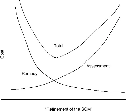
FIGURE 3-2 Illustration of the concept that the allocation of costs between remediation assessment (characterization) depends on how refined the site conceptual model is. The more is spent on assessment, the more precise the SCM. The more precise the SCM is, the less must be spent on the remedy. There is a level of refinement that is optimal for minimizing total cost.
containment or monitored natural attenuation strategies to be used, but would be inadequate for a source depletion technology like surfactant flushing.
* * *
The assessment and removal of a source are challenging tasks that are becoming even more challenging because of the difficulties and high costs associated with collecting measurements. The uncertainty resulting from limited data, hydrogeologic variability, and other factors must be taken into account when evaluating and selecting technologies for source remediation. Most source remediation studies circumvent an objective and systematic analysis of data and evaluation of uncertainty with respect to delineating the source zone and predicting the effectiveness of remediation (although there are frequently used statistical
models of human health risk from, e.g., contaminated groundwater). This is unfortunate because such an analysis can provide a better appreciation of the chances of success of a proposed remediation scheme and guidance on how to improve the scheme through additional measurements. Box 3-4 summarizes the progression and intensity of source zone characterization efforts carried out at the relatively small-scale Camp Lejeune, North Carolina. After the development of the overall site conceptual model, which included a preliminary effort focused on defining the source zone and local hydrogeology, this site was selected as a test site for source remediation via surfactant flushing. This project typifies the level of pre- and post-remedial action source zone characterization required to adequately address the uncertainty associated with such an effort.
REPERCUSSIONS OF INADEQUATE SOURCE CHARACTERIZATION
It is unfortunate that source remediation, especially at complex sites, is usually attempted in the absence of adequate source zone characterization. Impediments to fully understanding source areas are technical, economic, and institutional. For example, the site geology may be such that the technology to delineate a source zone is currently inadequate. Alternatively, the budget allocated for site characterization may be depleted long before the above questions have been conclusively answered. Third, stakeholders and the institutions funding the cleanup may lose patience with the process and call for remedial action to begin. Despite the technical challenges, some level of source zone characterization is indispensable for the effective management of an environmental restoration effort. Severe overestimation of the source size may inflate the cost of remediation efforts to exorbitant levels. Conversely, missing the source material will jeopardize the success of the cleanup and will require additional characterization and restoration work. Source zone assessment must be an integral part of the site characterization process, and failure to adequately characterize a source zone can have major repercussions in terms of future risk.
The following scenarios are intended to illustrate the ramifications of inadequate source zone characterization. All three scenarios are based on a hypothetical DNAPL-contaminated site that has reached a relatively late stage of the characterization process. The hydrogeologic setting is best characterized as a layered Type I and II system (see Chapter 2), where a shallow sand aquifer is separated (to an unknown extent) from an underlying aquifer by a low-permeability clay layer. The site exhibits elevated contaminant concentrations in groundwater near the suspected source area, but data are relatively sparse and variable, and the specific geometry of the source zone is highly uncertain. In one case, the decision is made to forego any additional source zone characterization and begin remediation. In the other two cases, it is decided to dedicate differing amounts of additional time and resources to source zone characterization. The scenarios are depicted in Figure 3-3.
|
BOX 3-4 MCB Camp Lejeune Site 88 is an example of a source depletion action that was accomplished after an adequate amount of source zone characterization was completed (ESTCP, 2001; NFESC, 2001, 2002). The potential PCE source zone area was initially identified at this former dry cleaning facility using chemical usage history and conventional site characterization techniques, such as borehole drilling and groundwater monitoring. Extensive and dense physical sampling efforts in the form of cone penetrometer and soil borings were first undertaken to map the soil lithology in terms of the permeability contrasts and porosity distributions that offer clues as to spatial DNAPL distribution. At the same time, chemical analysis of core samples was used, along with measured organic carbon content, to develop a more direct line of evidence regarding the distribution. As certainty about the DNAPL distribution above and along the clay unit began to increase, source remediation was presented as a potential objective, and wells were installed in and around the source zone. Using these wells, more specific characterization strategies, such as pump tests and partitioning interwell tracer tests (PITT), were undertaken to estimate the integrity of the clay unit as a capillary barrier and to estimate the volume of DNAPL in the source zone. By the end of the pre-removal characterization activity, three injection, six extraction and two hydraulic control wells were situated within the roughly 10-m by 10-m source zone area, which had already been densely probed by means of cone penetrometry and core sampling. This level of characterization was necessary to evaluate the feasibility of the surfactant-enhanced aquifer remediation (SEAR) source remediation technology and prepare for its application. Evaluation of the SEAR technology at Camp Lejeune involved extensive additional characterization efforts. Pre- and post-SEAR PITTs were used to estimate the amount of DNAPL volume remaining in the source zone, and 60 post-SEAR confirmational core samples were collected from within the small source zone and analyzed. The results from these characterization efforts suggested that while 92 percent to 95 percent of the DNAPL was removed from the permeable portions of the source zone, only 72 percent was removed overall. However, post-SEAR characterization and analyses suggested that the residual DNAPL was as unavailable to dissolution as it had been to the surfactant flushing. Subsequent modeling and flux reduction also indicate this 72 percent mass removal was accompanied by a greater than 90 percent reduction in the dissolution flux emanating from the source zone (Jayanti and Pope, 2004). Follow-up groundwater monitoring efforts aimed at confirming the sufficiency of this reduction in terms of plume size are ongoing. It is important to emphasize that, with the exception of the PITT, conventional characterization procedures were employed to characterize the source zone at Camp Lejeune. |
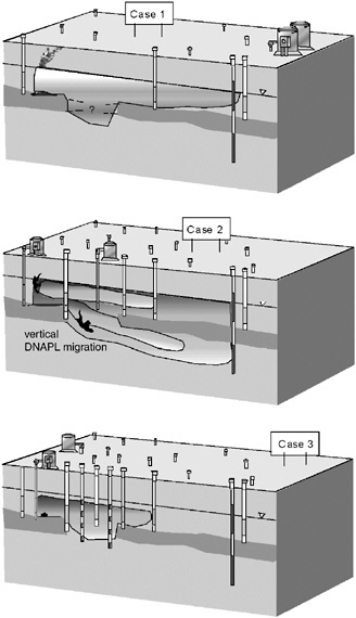
FIGURE 3-3 Illustration of potential repercussions of inadequate source zone characterization in the case of a poorly defined, discontinuous clay layer. Case 1 represents a prolonged pump-and-treat effort that will contain the source but not deplete the source in the short term. In Case 2, a chemical flushing technology is applied prematurely and results in the migration of a portion of the DNAPL to the lower aquifer. In Case 3, adequate source zone characterization leads to an accurate evaluation of the extent of the source and to more successful execution of the chemical flushing technology, substantial source strength reduction, and subsequent monitored natural attenuation.
Illustrative Case 1: Minimal Source Zone Characterization. Despite the uncertainty associated with the existence and nature of DNAPL at the site, the horizontal extremities of the plume seem reasonably well defined. Thus, one alternative is to forego any additional source zone characterization and implement a conventional pump-and-treat strategy. Personnel working on the site have experience in the hydraulic capture and treatment of the extracted water. The decision makers are wary of attempting source zone remediation, fearing that it will fail in the face of the uncertainties about the underlying clay layer, source size, and source strength. Thus, source zone remediation is not attempted and a conservative pump-and-treat plan is adopted.
Given their prior decision to halt site characterization, the decision makers have selected a reasonable remedial plan. Negative consequences might have resulted if source zone remediation actions had been undertaken with the inadequate characterization data. First, the costs incurred by this would likely produce limited benefits. Second, additional costs may arise if the source remediation attempt results in transferring portions of the source deeper or into less accessible regions of the subsurface. However, because the source material is not efficiently reduced by the pump-and-treat remedy, the prognosis for this scenario is that there will be a long-term operation and maintenance horizon with costs continuing indefinitely.
Illustrative Case 2: Insufficient Source Zone Characterization. In Case 2, the decision makers determine that the potential benefits of source zone remediation (e.g., plume size reduction to within a compliance boundary and reduced time to site closure) make additional source zone characterization worth pursuing. Thus, the decision makers choose to allocate additional resources toward source zone characterization, although their technical staff is relatively less experienced in this aspect of site assessment. A firm time limit of one year is set to ensure that the source zone characterization process does not delay remedial actions for too long. Additional core samples are collected, and monitoring wells are installed in and around the suspected source area. At the end of the one-year period, the corresponding data improve the areal resolution of the source zone, but the vertical extent remains highly uncertain. The decision makers assume that a clay layer identified in the source area is sufficiently continuous to provide a capillary barrier, and the decision is made to design and execute an aggressive chemical flushing technology aimed at mobilizing and extracting the DNAPL (see Chapter 5 for technologies).
In this case, the decision makers have allowed a predetermined time limit to control the quality of the source zone characterization effort. The fact that the clay unit in question is actually not continuous in the area of the source means that the likelihood of success is low. In the end, the costs incurred by the source remediation action are wasted because the mobilization technology will likely drive DNAPL through the discontinuity and deeper into the subsurface.
Illustrative Case 3: Adequate Source Zone Characterization. The rationale of the decision makers in Case 3 is similar to that in Case 2 with one exception: in Case 3 they recognize the importance of allowing the source zone characterization to continue until uncertainty regarding the feasibility of partial source depletion is reduced to a manageable level. Outside expertise in the areas of source zone characterization and remediation has been retained to assist the site personnel. As in the previous case, additional core sampling is undertaken, and monitoring wells are installed in and around the suspected source area. At the end of the one-year period, the vertical extent of the source remains highly uncertain, and additional time and resources are allocated to the install and monitor multilevel monitoring wells to better resolve the vertical concentration gradient. At the end of the second year, the source zone and underlying clay unit have been resolved with enough certainty to correctly identify a less aggressive DNAPL solubilization strategy. The decision makers elect to design and execute a chemical flushing technology to reduce the source strength, but they orientate flushing and recovery hydraulics to guard against DNAPL migration through the discontinuity in the clay layer.
In this case the decision makers have expended more time and money during source characterization relative to Cases 1 and 2, respectively. In doing so, they have maximized the likelihood of successful source depletion. The chemical flushing plan is designed, executed, and evaluated, requiring an additional two years. However, according to pre- and postremediation dissolution flux estimates, 95 percent of the original source strength has been depleted. Modeling efforts predict a reduction in source strength, and monitored natural attenuation becomes an acceptable alternative for all stakeholders. Four years have passed since the decision to aggressively characterize the source zone, but operations and maintenance costs for the site are now low compared to those for the previous two cases. (It is not clear, however, whether life cycle costs, which take into account all relevant expenditures over the life of a hazardous waste site, are lower for the third scenario. See Chapter 4 for an in-depth discussion of life cycle analysis.)
* * *
Although these case studies are hypothetical, they serve to illustrate common themes in source zone characterization. For many reasons, responsible parties may be disinclined to commit the considerable funds required for comprehensive source zone characterization. Source identification and delineation are considered technically challenging and expensive, and they may reveal that the contamination problem is more extensive than previously thought, leading to even larger costs. Detailed source zone characterization can be unappealing to the responsible party since it may pave the way to source remediation regarded as complicated, costly, and perhaps of questionable effectiveness. Indeed, it is worthwhile to note
that overzealous source zone characterization such as excessive source zone drilling without proper precautions can remobilize DNAPL or create worker safety issues related to chemical exposure. However, a nonexistent or halfhearted characterization attempt may unnecessarily lead to containment efforts with no foreseeable end (Case 1) or compromise the effectiveness of any source remediation effort (see Case 2). Avoiding these undesirable consequences requires that the decision process leading to a specific source assessment and mitigation plan be dynamic and iterative. That is, on the basis of preliminary information, funds are allocated for characterization and remediation. As new information is obtained, the goals of the remediation campaign must be revisited and are likely to change. Once it becomes clear that source remediation is a potentially promising approach, one must evaluate, on the basis of the hydrogeochemical conditions and the types of the contaminants, what methods of remediation are appropriate and what levels of characterization they require. While this iterative process may appear time-consuming in the face of stakeholders’ desires to expedite cleanup, a rush to judgment on the nature and extent of the contamination can worsen site conditions and result in contamination inadvertently remaining behind. The public is more likely to respond positively to an honest acknowledge of the limitations on and uncertainties in the data than to perceived certainty that is later revealed as incorrect.
CONCLUSIONS AND RECOMMENDATIONS
The committee’s review of dozens of case studies of source characterization and remediation (see Chapter 1) suggests that at many DNAPL or explosives-contaminated sites there is inadequate site characterization to support the remediation strategies that were employed and/or to evaluate the actual results of the trial in terms of improvement in water quality, the fraction of the total mass removed, or other appropriate success metrics. In several cases the data were not adequate to determine if there even was a source. This is most likely due to pressure to show progress and meet deadlines, to financial constraints, or to unclear objectives.
Despite these shortcomings, the Army has made substantial progress at improving its source characterization activities, particularly with respect to confirming that DNAPL is present. The Army case studies reviewed by the committee also suggest that the development of site conceptual models is evolving rapidly in parallel with improved Army characterization efforts. At Fort Lewis, for example, a number of nontraditional characterization technologies were used including CPT-LiF, MIP, GPR, resistivity, dye studies, and multilevel wells. Other sites using innovative technologies included Watervliet, where down-hole geophysics were used to characterize the fractured rock, and Redstone Arsenal, where a major effort was mounted to characterize flow in a complex karst terrain. These efforts are impressive, given that karst, epikarst, and fractured bedrock settings
are resistant to detailed source characterization using existing technologies. The Army’s realization of the difficulty of site characterization in these hydrogeologic settings has led it to consider applying for technical impracticability waivers (e.g., at Anniston and Letterkenny). Such waivers are appropriate if the objectives of remediation are clearly defined and if sufficient data are obtained to show that the objectives cannot be met by any feasible approach.
The following recommendations regarding source characterization are made.
Source characterization should be performed iteratively throughout the cleanup process to identify remedial objectives, metrics for success, and remediation techniques. All sites require some amount of source characterization to support the development and refinement of a site conceptual model. In general, successful source remediation requires information on the nature of the source material, on the site hydrogeology, on the source zone distribution, and on the site biogeochemistry. However, the level of characterization effort required and the tools used at any given site are dependent on site conditions, on the cleanup objectives chosen, and on the technology chosen to achieve those objectives.
An evaluation of the uncertainties associated with the conceptualization of the source strength and location, with the hydrogeologic characteristics of the subsurface, and with the analytical data from sampling is essential for determining the likelihood of achieving success. This is often accomplished through the use of statistical, inverse, and stochastic inverse methods. Unfortunately, quantitative uncertainty analysis is rarely practiced at hazardous waste sites. Obtaining a better handle on uncertainty via increased source characterization would allow eventual remediation to be more precise. It is likely that at most sites, there is not an optimum combination of resources and effort expended on source characterization and thus uncertainty reduction vs. remedial action.
REFERENCES
American Petroleum Institute (API). 2003. Groundwater remediation strategies tool. Publication Number 4730. Washington, DC: API Publishing Services.
American Society of Civil Engineers (ASCE). 2003. Long-term groundwater monitoring: the state of the art. Prepared by the Task Committee on the State of the Art in Long-Term Groundwater Monitoring Design. Reston, VA: American Society of Civil Engineers.
American Society for Testing and Materials (ASTM). 2003. Standard guide for developing conceptual site models for contaminated sites. Document No. ASTM E1689-95(2003)e1. West Conshohocken, PA: ASTM International.
Annable, M. D., P. S. C. Rao, K. Hatfield, W. D. Graham, and C. G. Enfield. 1998. Partitioning tracers for measuring residual NAPLs for field-scale test results. J. Env. Eng 124:498–503.
Bair, S., C. M. Safreed, and E. A. Stasny. 1991. A Monte Carlo-based approach for determining travel time-related capture zones of wells using convex hulls as confidence regions. Ground Water 29 (6):849–855.
Bekins, B. A., I. M. Cozzarelli, E. M. Godsy, E. Warren, H. I. Essaid, and M. E. Tuccillo. 2001. Progression of natural attenuation processes at a crude oil spill site. II. Controls on spatial distribution of microbial populations. J. Contam. Hydrol. 53:387–406.
Bockelmann, A., T. Ptak, and G. Teutsch. 2001. An analytical quantification of mass fluxes and natural attenuation rate constants at a former gasworks site. J. Contaminant Hydrology 53:429– 453.
Boonstra, J. 1999. Well hydraulics and aquifer tests. Pp. 8.1–8.34 In: The Handbook of Groundwater Engineering. J. W. Delleur (ed.). Boca Raton, FL: CRC Press.
Borden, R. C., R. A. Daniel, L. E. LeBrun IV, and C. W. Davis. 1997. Intrinsic biodegradation of MTBE and BTEX in a gasoline-contaminated aquifer. Water Resources Research 33(5):1105–1115.
Capilla, J. E., J. Rodrigo, and J. J. Gomez-Hernandez. 1998. Worth of secondary data compared to piezometric data for the probabilistic assessment of radionuclide migration. Stoch. Hydrol. Hydraul. 12 (3):171–190.
Carlin, B. P., and T. A. Louis. 2000. Bayes and empirical Bayes methods for data analysis. Boca Raton, FL: Chapman & Hall/CRC.
Chapelle, F. H., P. B. McMahon, N. M. Dubrovsky, R. F. Fujii, E. T. Oaksford, and D. A. Vroblesky. 1995. Deducing the distribution of terminal electron accepting processes in hydrologically diverse groundwater systems. Water Res. Res. 31:359–371.
Chen, J., S. S. Hubbard, and J. Rubin. 2001. Estimating the hydraulic conductivity at the South Oyster site from geophysical tomographic data using Bayesian techniques based on the normal linear regression model. Water Resources Research 37(6):1603–1613.
Christakos, G. 1990. A Bayesian/maximum-entropy view to the spatial estimation problem. Mathematical Geology 22(7):763–777.
Christakos, G., and B. R. Killam. 1993. Sampling design for classifying contaminant level using annealing search algorithms. Water Resources Research 29(12):4063–4076.
Cohen, R. M., J. M Mercer, and J. Matthews. 1993. DNAPL Site Evaluation. C. K. Smoley (ed.) Boca Raton, FL: CRC Press.
Copty, N., Y. Rubin, and G. Mavko. 1993. Geophysical-hydrological identification of field permeabilities through Bayesian updating. Water Resources Research 29(8):2813–2825.
Crockett, A. B., T. F. Jenkins, H. D. Craig, and W. E. Sisk. 1998. Overview of on-site analytical methods for explosives in soil. Special Report 98-4. Hanover, NH: U.S. Army Corps of Engineers, Cold Regions Research and Engineering Laboratory.
Dagan, G., and S. P. Neuman. 1997. Subsurface Flow and Transport: A Stochastic Approach. Cambridge, UK: Cambridge Univ. Press.
Dela Barre, B. K., T. C. Harmon, and C. V. Chrysikopoulos. 2002. Measuring and modeling the dissolution of a nonideally shaped dense nonaqueous phase liquid (DNAPL) Pool in a saturated porous medium. Water Resources Research. 38(8):U143–U156.
Einarson, M. D., and D. M. Mackay. 2001. Predicting impacts of groundwater contamination. Environmental Science and Technology 35(3):66A–73A.
Environmental Protection Agency (EPA). 1992. Estimating potential for occurrence of DNAPL at Superfund sites. Washington, DC: EPA of Solid Waste and Emergency Response.
EPA. 1993. Handbook: Approaches for the remediation of federal facility sites contaminated with explosive or radioactive wastes. EPA/625/R-93/013. Washington, DC: EPA Office of Research and Development.
EPA. 2001. Using the Triad approach to improve the cost-effectiveness of hazardous waste site cleanups. EPA-542-R-01-016. Washington, DC: EPA.
EPA. 2003a. The DNAPL Remediation Challenge: Is There a Case for Source Depletion? EPA 600/ R-03/143. Washington, DC: EPA Office of Research and Development.
EPA. 2003b. Using dynamic field activities for on-site decision making: a guide for project managers. EPA 540/R-03/002. Washington, DC: EPA Office of Solid Waste and Emergency Response.
EPA. 2004. Improving sampling, analysis, and data management for site investigation and cleanup. EPA 542-F-04-001a. Washington, DC: EPA Office of Solid Waste and Emergency Response.
Environmental Security Technology Certification Program (ESTCP). 2001. Surfactant enhanced DNAPL removal. ESTCP Cost and Performance Report CU-9714. Washington, DC: ESTCP.
Feenstra, S. J., A. Cherry, and B. L. Parker. 1996. Conceptual models for the behavior or dense non-aqueous phase liquids DNAPLs) in the subsurface. In: Dense Chlorinated Solvents and Other DNAPLs in Groundwater. J. F. Pankow and J. A. Cherry (eds.). Portland, OR: Waterloo Press.
Freeze, R. A., B. R. James, J. Massmann, T. Sperling and L. Smith. 1992. Hydrogeological decision analysis: (4) the concept of data worth and its use in the development of site investigation strategies. Ground Water 30(4):574–588.
Frind, E. O., J. W. Molson, M. Schirmer, and N. Guiguer. 1999. Dissolution and mass transfer of multiple organics under field conditions: the Borden emplaced source. Water Resources Research 35(3):683–694.
Gelman, A., J. B. Carlin, H. S. Stern, and D. B. Rubin. 1995. Bayesian Data Analysis. Boca Raton, FL: CRC Press.
Ginn, T. R., and J. H. Cushman. 1990. Inverse methods for subsurface flow: a critical review of stochastic techniques. Stoch. Hydrol. Hydraul. 4:1–26.
Griffin, T. W., and K. W. Watson. 2002. A comparison of field techniques for confirming dense nonaqueous phase liquids. Ground Water Monitoring and Remediation 22:48–59.
Hatfield, K., M. D. Annable, S. Kuhn, P. S. C. Rao, and T. Campbell. 2002. A new method for quantifying contaminant flux at hazardous waste sites. Pp. 25–32 In: Groundwater Quality: Natural and Enhanced Restoration of Groundwater Protection. S. F. Thornton and S. E. Oswald (eds.). IAHS Publication No. 275. Oxfordshire, UK: IAHS Press.
Hendrickson, E. R., J. A. Payne, R. M. Young, M. G. Starr, M. P. Perry, S. Fahnestock, D. E. Ellis, and R. C. Ebersole. 2002. Molecular analysis of Dehalococcoides 16S ribosomal DNA from chloroethene-contaminated sites throughout North America and Europe. Appl. Environ. Microbiol. 68(2):485–495.
Hewitt, A. D., and T. F. Jenkins. 1999. On-site method for measuring nitroaromatic and nitramine explosives in soil and groundwater using GC-NPD. Special Report 99-9. Hanover, NH: U.S. Army Corps of Engineers, Cold Regions Research and Engineering Laboratory.
Holling, C. S. (ed.). 1978. Adaptive environmental assessment and management. New York: John Wiley & Sons.
Houlihan, M. F., and P. C. Lucia. 1999. Groundwater monitoring. Pp. 24.1-24.40 In: The Handbook of Groundwater Engineering. J. W. Delleur (ed.). Boca Raton, FL: CRC Press.
Hubbard, S. S., J. Chen, J. Peterson, E. L. Majer, K. H. Williams, D. J. Swift, B. Mailloux, and J. Rubin. 2001. Hydrogeological characterization of the south oyster bacterial transport site using geophysical data. Water Resources Research 37(10):2431–2456.
Hyndman, D. W. 1999. Geophysical and tracer characterization methods. Pp. 11.1–11.30 In: The Handbook of Groundwater Engineering. J. W. Delleur (ed.). Boca Raton, FL: CRC Press.
Interstate Technology and Regulatory Council (ITRC). 2002. DNAPL source reduction: facing the challenge. Regulatory overview. Washington, DC: Interstate Technology and Regulatory Council.
ITRC. 2003. Technology overview: an introduction to characterizing sites contaminated with DNAPLs. Washington, DC: Interstate Technology and Regulatory Council.
James, B. R., and R. A. Freeze. 1993. The worth of data in predicting aquitard continuity in hydrogeological design. Water Resources Research 29(7):2049–2065.
James, B. R., and S. M. Gorelick. 1994. When enough is enough: the worth of monitoring data in aquifer remediation design. Water Resources Research 30(12):3499–3513.
Jarvis, K. D., and R. J. Knight. 2002. Aquifer heterogeneity from SH-wave seismic impedance inversion. Geophysics 67(5):1548–1557.
Jayanti, S. 2003. Modeling tracers and contaminant flux in heterogeneous aquifers. PhD dissertation, University of Texas at Austin, August 2003.
Jayanti, S., and G. A. Pope. 2004. Modeling the benefits of partial mass reduction in DNAPL source zones. Proceedings of the Fourth International Conference on Remediation of Chlorinated and Recalcitrant Compounds, Monterey, CA, May 24–27, 2004.
Jin, M., R. E. Jackson, G. A. Pope, and S. Taffinder. 1997. Development of partitioning tracer tests for characterization of nonaqueous-phase liquid-contaminated aquifers. Pp. 919–930 In: The Proceedings of the SPE 72nd Annual Technical Conference and Exhibition, San Antonio, TX, October 5–8, 1997.
Jury, W. A., W. R. Gardner, and W. H. Gardner. 1991. Soil Physics, Fifth Edition. New York: John Wiley and Sons, Inc.
Kennedy, P. L., and A. D. Woodbury. 2002. Geostatistics and Bayesian updating for transmissivity estimation in a multiaquifer system in Manitoba, Canada. Ground Water 40(3):273–283.
Kitanidis, P. K., and K.-F. Shen. 1996. Geostatistical interpolation of chemical concentration. Adv. Water Resour. 19(6):369–378.
Kitanidis, P. K. 1997. Introduction to Geostatistics. Cambridge, UK: Cambridge University Press. Pp. 249.
Kitanidis, P. K. 1999. Geostatistics: interpolation and inverse problems. Pp. 12.1–12.20 In: The Handbook of Groundwater Engineering. J. W. Delleur (ed.). Boca Raton, FL: CRC Press.
Kram, M. L., A. A. Keller, J. Rossabi, and L. G. Everett. 2001. DNAPL characterization methods and approaches. I. Performance comparisons. Ground Water Monitoring and Remediation 21:109–123.
Kram, M. L., A. A. Keller, J. Rossabi, and L. G. Everett. 2002. DNAPL characterization methods and approaches. II. Cost comparisons. Ground Water Monitoring and Remediation 22:46-61.
Kristoff, F. T., T. W. Ewing, and D. E. Johnson. 1987. Testing to determine relationship between explosive contaminated sludge components and reactivity. Final Report to U.S. Army Toxic and Hazardous Materials Agency, by Hercules Aerospace Company (Radford Army Ammunition Plant) for Arthur D. Little, Inc.
Lee, K. N. 1993. Compass and gyroscope: integrating science and politics for the environment. Covelo, CA: Island Press.
Lee, K. N. 1999. Appraising adaptive management. Conservation Ecology 3(2):3.
Lee, S. -I., and P. K. Kitanidis. 1991. Optimal estimation and scheduling in aquifer remediation with incomplete information. Water Resources Research 27(9):2203–2217.
Lendvay, J. M., F. E. Löffler, M. Dollhopf, M. R. Aiello, G. Daniels, B. Z. Fathepure, M. Gebhard, R. Heine, R. Helton, J. Shi, R. Krajmalnik-Brown, C. L. Major, Jr., M. J. Barcelona, E. Petrovskis, R. Hickey, J. M. Tiedje, and P. Adriaens. 2003. Bioreactive barriers: a comparison of bioaugmentation and biostimulation for chlorinated solvent remediation. Environ. Sci. Technol. 37(7):1422–1431
Londergan, J. T., M. Jin, J. A. K. Silva, and G. A. Pope. 2000. Determination of spatial distribution and volume of chlorinated solvent contamination. In: The Proceedings of the Second International Conference on Remediation of Chlorinated and Recalcitrant Compounds, Monterey, CA, May 22–25, 2000.
Lovley, D. R. and R. T. Anderson. 2000. Influence of dissimilatory metal reduction on fate of organic and metal contaminants in the subsurface. Hydrogeol. J. 8(1):77–88.
Mackay, D. M., W. Y. Shiu, A. Maijanen, and S. Feenstra. 1991. Dissolution of non-aqueous phase liquids in groundwater. J. Contam. Hydrol. 8(1):23–42.
Mariner, P. E., M. Jin, J. E. Studer, and G. A. Pope. 1999. The first vadose zone partitioning interwell tracer test (PITT) for NAPL and water residual. Environ. Sci. Technol. 33(16):2825–2828.
Massmann, J., R. A. Freeze, L. Smith, T. Sperling, and B. James. 1991. Hydrogeological decision analysis: 2. applications to groundwater contamination. Groundwater 29(4):536–548.
McGuire, J. T., E. W. Smith, D. T. Long, D. W. Hyndman, S. K. Haack, M. J. Klug, and M. A. Velbel. 2000. Temporal variations in parameters reflecting terminal electron accepting processes in an aquifer contaminated with waste fuel and chlorinated solvents. Chem. Geol. 169:471–485.
McLaughlin, D., and L. R. Townley. 1996. A reassessment of the groundwater inverse problem. Water Resources Research 32(5):1131–1161.
Meinardus, H. W., V. Dwarakanath, J. Ewing, G. J. Hirasaki, R. E. Jackson, M. Jin, J. S. Ginn, J. T. Londergan, C. A. Miller, and G. A. Pope. 2002. Performance assessment of NAPL remediation in heterogeneous alluvium. J. Contaminant Hydrology 54:173–193.
Moore, D. S., and G. P. McCabe. 1999. Introduction to the Practice of Statistics. New York: Freeman.
Naval Facilities Engineering Service Center (NFESC). 2001. Cost and performance report of surfactant-enhanced DNAPL removal at Site 88, Marine Corps Base Camp Lejeune, North Carolina. Environmental Security Technology Certification Program (ESTCP) Final Report.
NFESC. 2002. Surfactant-enhanced aquifer remediation design manual. Naval Facilities Command Technical Report TR-2206-ENV.
National Research Council (NRC). 1999. Environmental Cleanup at Navy Facilities: Risk-Based Methods. Washington, DC: National Academy Press.
NRC. 2000. Natural Attenuation for Groundwater Remediation. Washington, DC: National Academy Press.
NRC. 2003. Environmental Cleanup at Navy Facilities: Adaptive Site Management. Washington, DC: National Academies Press.
Olea, R. 1999. Geostatistics for Engineers and Earth Scientists. Bingham, MA: Kluwer Academic Publishers.
Paillet, F. L. 1998. Flow modeling and permeability estimation using borehole flow logs in heterogeneous fractured formation. Water Resources Research 34:997–1010.
Pannone, M., and P. K. Kitanidis. 2001. Large-time spatial covariance of concentration of conservative solute and application to the Cape Cod tracer test. Transport in Porous Media 42:109–132.
Peck, R. B. 1969. Advantages and limitations of the observational method in applied soil mechanics. Geotechnique. 44(4):619–636.
Phelan, J., and J. L. Barnett. 2001. Phase partitioning of TNT and DNT in soils. Report SAND2001-0310. Albuquerque, NM: Sandia National Laboratories.
Phelan, J. M., S. W. Webb, J. V. Romero, J. L. Barnett, F. Griffin, and M. Eliassi. 2003. Measurement and modeling of energetic material mass transfer to soil pore water – Project CP-1227 Annual Technical Report. Sandia National Laboratories Report SAND2003-0153. Albuquerque, New Mexico: Sandia.
Poeter, E. P., and M. C. Hill. 1997. Inverse models: a necessary next step in groundwater modeling. Ground Water 35(2):250–260.
Rao, P. S. C., M. D. Annable, and H. Kim. 2000. NAPL source zone characterization and remediation technology performance assessment: recent developments and applications of tracer techniques. J. Contam. Hydrol. 45:63–78.
Robert, C. P., and G. Casella. 1999. Monte Carlo Statistical Methods. New York: Springer. 424 pp.
Rouhani, S., A. P. Georgakakos, P. K. Kitanidis, H. A. Loaiciga, R. A., Olea, and S. R. Yates. 1990a. Geostatistics in geohydrology. I. Basic concepts. ASCE J. of Hydraulic Engineering 116(5):612–632.
Rouhani, S., A. P. Georgakakos, P. K. Kitanidis, H. A. Loaiciga, R. A., Olea, and S. R. Yates. 1990b. Geostatistics in geohydrology. II. Applications. ASCE J. of Hydraulic Engineering 116(5):633–658.
Rubin, Y. 2003. Applied Stochastic Hydrogeology. Oxford, UK: Oxford University Press.
Rubin, Y., S. S. Hubbard, A. Wilson, and M. A. Cushey. 1999. Aquifer characterization. Pp. 10.1–10.68 In: The Handbook of Groundwater Engineering. J. W. Delleur (ed.). Boca Raton, FL: CRC Press.
Saito, H., and P. Goovaerts. 2000. Geostatistical interpolation of positively skewed and sensored data in a dioxin-contaminated site. Environ. Sci. Technol. 34:4228–4235.
Sciortino, A., T. C. Harmon, and W. W-G. Yeh. 2000. Inverse modeling for locating dense non-aqueous pools in groundwater under steady flow conditions. Water Resources Research 36(7):1723–1736.
Sciortino, A., T. C. Harmon, and W. W-G. Yeh. 2002. Experimental design and model parameter estimation for locating a dissolving DNAPL pool in groundwater. Water Resources Research 38(5):U290–U298.
Shapiro, A. M. 2002. Cautions and suggestions for geochemical sampling in fractured rock. Ground Water Monitoring and Remediation 22:151–164.
Sposito, G. (Ed.). 1998. Scale Dependence and Scale Invariance in Hydrology. New York: Cambridge University Press.
Terzaghi, K., R. B. and Peck. 1967. Soil Mechanics in Engineering Practice. New York: Wiley.
Thiboutot, S., G. Ampleman, S. Brochu, R. Martel, G. Sunahara, J. Hawari, S. Nicklin, A. Provatas, J. C. Pennington, T. F. Jenkins, and A. Hewitt. 2003. Protocol for Energetic Materials-Contaminated Sites Characterization. The Technical Cooperation Program, Wpn Group -Conventional Weapon Technology, Technical Panel 4, Energetic Materials and Propulsion Technology, Final Report Volume II.
Tiedeman, C. R., and P. A. Hsieh. 2001. Assessing an open-hole aquifer test in fractured crystalline rock. Ground Water 39:68–78.
Walters, C. 1986. Adaptive management of renewable resources. New York: Macmillan.
Walters, C. 1997. Challenges in adaptive management of riparian and coastal ecosystems. Conservation Ecology 1(2):1.
Walters, C. J., and C. S. Holling. 1990. Large-scale management experiments and learning by doing. Ecology 71: 2060–2068.
Williams, J. H., and F. L. Paillet. 2002. Using flowmeter pulse tests to define hydraulic connections in the subsurface: a fractured shale example. Journal of Hydrology 265:100–117.
Witt, M. E., G. M. Klecka, E. J. Lutz, T. A. Ei, N. R. Grasso, and F. H. Chapelle. 2002. Natural attenuation of chlorinated solvents at Area 6, Dover Air Force Base: groundwater biogeochemistry. J. Contam. Hydrol 57:61–80.
Yeh, W. W.-G. 1986. Review of parameter identification procedures in groundwater hydrology: the inverse problem. Water Resources Research 22(1):95–108.


