
5
Treatment of Hydrolysates and Residual Wastes
Processes selected by the Army for destruction of the chemical agents and associated energetics currently stored at Blue Grass Army Depot are hydrolysis as the core process, followed by supercritical water oxidation (SCWO) for secondary treatment of the hydrolysates. A destruction and removal efficiency of 99.9999 percent is required for agent hydrolysis. Both agent and energetics hydrolysates contain residual organics that require further treatment by SCWO.
The Army also specified that all other hazardous materials, which are listed in Table 5-1, should be destroyed on site. The destruction methods are planned to be as follows:
-
Metal parts from drained and washed munitions are to be treated in a metal parts treater (MPT).
-
Solid residue from the energetics batch hydrolyzers is to be treated by a heated discharge conveyor (HDC).
-
Miscellaneous nonmetallic materials, designated as dunnage, are to be hydropulped and treated by SCWO, or to be treated in the MPT, or, if uncontaminated, shipped off-site for disposal. Other miscellaneous materials, designated secondary wastes, are to be treated in the MPT, hydropulped and treated by SCWO, or, if uncontaminated, shipped off-site for disposal.
This chapter discusses the use of SCWO for treatment of hydrolysates and dunnage; dunnage shredding and handling; the process train for treatment of metal parts, including the treatment of MPT offgases; and the disposition of secondary wastes.
SUPERCRITICAL WATER OXIDATION
Basic Principles
Water at temperatures greater than 705°F (374°C) and pressures greater than 3,205 psi (221 bar) is in the supercritical state. In that state, it exists in a single phase that differs significantly in its physical properties from water in its normal liquid and vapor phases. Typical SCWO operating conditions are T ![]() 1112°F (600°C) and P
1112°F (600°C) and P ![]() 3,626 psi (250 bar). Under these conditions, the density of supercritical water is roughly 100 kg/m3 (compared with 1,000 kg/m3 for liquid water and approximately 10-30 kg/m3 for steam used in commercial power plants). At supercritical density, the intermolecular distances are correspondingly greater than those that characterize normal liquid water. As a result, the hydrogen bonding tendency of water is greatly attenuated, and water in this state behaves much more like a typical nonpolar solvent. In particular, most organic species, including alkanes, are completely soluble in supercritical water. In addition, molecular oxygen is fully miscible in supercritical water. The greatly enhanced solubility and higher diffusivity of oxygen in the supercritical phase eliminates the usual interfacial resistance to oxygen transport in liquid water. In SCWO, the oxidation rate is typically controlled by chemical kinetics rather than by oxygen transport. At 1112°F (600°C), very high
3,626 psi (250 bar). Under these conditions, the density of supercritical water is roughly 100 kg/m3 (compared with 1,000 kg/m3 for liquid water and approximately 10-30 kg/m3 for steam used in commercial power plants). At supercritical density, the intermolecular distances are correspondingly greater than those that characterize normal liquid water. As a result, the hydrogen bonding tendency of water is greatly attenuated, and water in this state behaves much more like a typical nonpolar solvent. In particular, most organic species, including alkanes, are completely soluble in supercritical water. In addition, molecular oxygen is fully miscible in supercritical water. The greatly enhanced solubility and higher diffusivity of oxygen in the supercritical phase eliminates the usual interfacial resistance to oxygen transport in liquid water. In SCWO, the oxidation rate is typically controlled by chemical kinetics rather than by oxygen transport. At 1112°F (600°C), very high
TABLE 5-1 Treatment Methods for Different Waste Stream Materials During Normal Disposal Campaigns and Closure
|
Material Type |
Material Category |
Waste Stream |
Components |
Treatment Method |
|
|
Normal Campaign |
Closure |
||||
|
Liquid, combustible |
Lubricant |
Used oil-based lubricant fluids |
Misc. fluids |
DSH/SCWO |
MPT |
|
Liquid, noncombustible |
Coolant |
Ethylene glycol or propylene glycol |
Misc. fluids |
DSH/SCWO |
MPT |
|
Liquid, noncombustible |
Hydraulic |
Used water-based hydraulic fluid |
Misc. fluids |
DSH/SCWO |
MPT |
|
Solid, combustible |
Carbon |
Regular charcoal from MDB filters |
Carbon |
DSH/SCWO |
MPT |
|
Solid, combustible |
Carbon |
Metal impregnated charcoal from mask filters |
Cu, Zn, Cr |
DSH/SCWO |
MPT |
|
Solid, combustible |
Cellulosic |
Wood from maintenance cribbing |
Cellulose-based materials |
DSH/SCWO |
MPT |
|
Solid, combustible |
Cellulosic |
Wood munitions pallets and boxes |
Cellulose-based materials |
DSH/SCWO |
MPT |
|
Solid, combustible |
Elastomer |
Butyl boots |
Butyl rubber |
DSH/SCWO |
MPT |
|
Solid, combustible |
Elastomer |
Toxicological agent protective gear |
Butyl rubber |
DSH/SCWO |
MPT |
|
Solid, combustible |
Halogenated |
LSSa and equipment hoses |
Neoprene |
DSH/SCWO |
MPT |
|
Solid, combustible |
Halogenated |
Conveyer belt material |
PVC |
DSH/SCWO or MPT |
MPT |
|
Solid, combustible |
Halogenated |
DPE face shield |
PVC |
DSH/SCWO |
MPT |
|
Solid, combustible |
Halogenated |
DPE suits |
PVC |
DSH/SCWO |
MPT |
|
Solid, combustible |
Halogenated |
Face mask for Tyvek suit |
PVC |
DSH/SCWO |
MPT |
|
Solid, combustible |
Halogenated |
LSS and equipment hoses |
PVC (reinforced) |
DSH/SCWO |
MPT |
|
Solid, combustible |
Halogenated |
Gore-Tex fabric materials |
Teflon |
DSH/SCWO |
MPT |
|
Solid, combustible |
Plastic |
Tyvec suit |
Polyaramid materials |
DSH/SCWO |
MPT |
|
Solid, combustible |
Plastic |
Poly bags (5 mil) |
Polyethylene |
DSH/SCWO or MPT |
MPT |
|
Solid, combustible |
Plastic |
Poly bags (5 mil) |
Polyethylene |
DSH/SCWO or MPT |
MPT |
|
Solid, combustible |
Plastic |
Drum liners (20 mil) |
PVC |
DSH/SCWO |
MPT |
|
aLSS, life support system. SOURCE: Adapted from Bechtel Parsons Blue Grass Team response on May 7, 2005, to the committee’s request for information on February 2, 2005. |
|||||
destruction efficiencies are attained with residence times of 1 minute or less.
The reaction mechanisms for the destruction of organic compounds by SCWO generally involve free-radical chain reactions with oxidative radicals (mostly OH and OOH) (NRC, 1998). Thermal bond cleavage and polar or ionic reactions, including hydrolysis, also occur under these severe conditions. Aqueous organic wastes with sufficient fuel value can sustain the reaction temperatures, making supplemental fuel
unnecessary (NRC, 1998). Furthermore, the reaction products are benign. Carbon is converted to CO2 and nitrogen is largely converted to N2, although a small amount of N2O is also formed. The effluent does not contain NOx, SOx, or polychlorinated dioxins or furans. Lastly, because supercritical water is denser than steam, the reactor volumes are modest and the SCWO process is compatible with a treatment philosophy of react, hold, test, and release. Reviews of the SCWO process can be found elsewhere (Tester et al., 1993; Gloyna and Li, 1998; Shaw et al., 1991; Shaw and Dahmen, 2000).
Despite its important advantages, SCWO has not yet become a commercial success. Only one commercial plant has operated for an extended period. The Huntsman Corporation’s petrochemical plant, in Austin, Texas, was the first to run a commercial SCWO facility to destroy the organic waste and washdown water from its process stream. This facility was placed in operation in 1994 and apparently worked quite well for several years (NiDI, 1999; Shaw and Dahmen, 2000). Its feed stream was a dilute solution of alcohols and amines.
Because of the composition of the feed stream, the Huntsman plant was not prone to the problems of corrosion and plugging encountered at pilot plants designed for more complex feed streams that contain heteroatoms such as chlorine, fluorine, or phosphorus. Upon oxidation, these are converted to the corresponding mineral acids, which are extremely corrosive. To counter the corrosion, it is common practice to add caustic to the feed stream. This converts any acid to a salt. Unfortunately, for precisely the same reasons that supercritical water is a good solvent for most organic species, it is a very poor solvent for salts. The result is that the salts tend to precipitate, with associated fouling and plugging. Technologies used to deal with this precipitation have been discussed in some detail (Hodes et al., 2004; Marrone et al., 2004). The corrosion is typically an ionic process that proceeds best in a polar environment—the high subcritical regime. Thus, the heat-up and cool-down devices on either side of the supercritical water reactor (i.e., both the inlet and outlet regions) are particularly prone to rapid corrosion. The reactor itself is not spared from degradation due to corrosion, and frequent replacement of the reactor liner is planned for the SCWO units at the Blue Grass Chemical Agent Destruction Pilot Plant (BGCAPP).
SCWO Reactor Design for BGCAPP
As discussed in more detail below, the feed stream composition will first be adjusted to achieve a desired ratio of chlorides to sulfates and to avoid high phosphate concentrations. The stream will then be pressurized and continuously pumped into a titanium-lined pressure vessel (Bechtel Parsons, 2004k).
High-pressure air is injected into the annulus between the titanium liner and the chromium-molybdenum (Cr-Mo) steel vessel wall. The air flow acts to keep the pressure-bearing, outer steel shell below its maximum operating temperature of approximately 900°F. The pressures in the annulus and in the reactor proper are essentially equal, so that the titanium liner will not have to support any pressure-induced stresses. The heat of reaction provides the energy necessary for maintaining the temperature within the reactor.
Start-up of the SCWO system occurs in three steps:
-
Initial heating of the reactor with hot water,
-
Continued heating via oxidation of a supplementary fuel, and
-
Introduction of waste feed.
In Step 1, deionized feed water passes through an electric preheater and enters the reactor through the main feed nozzle. Control valves downstream of the reactor maintain the pressure at ~3,400 psig. As the reactor is heating, air flows into the system at a slow rate through the feed nozzle, and quench water is introduced at the bottom of the reactor. A low-flow, high-pressure air stream is also fed to the annular space between the removable liner and the reactor vessel. This purge stream prevents backflow of corrosive or combustible species into the annular space.
In Step 2, when the internal reactor temperature reaches ~750°F, 70 weight percent isopropyl alcohol and high-pressure air enter the reactor along with the supercritical feedwater through the feed nozzle. The isopropyl alcohol reacts exothermally with air, causing the reactor temperature to increase. The temperature is controlled to ~1200°F (650°C). The preheater is turned off. Fuel and air flows are increased to a combined flow rate of approximately 1,000 pounds per hour. Air flow is raised in conjunction with fuel flow to maintain a stoichiometric excess of oxygen in the reactor.
In Step 3, the flow of waste feed is started at a low flow rate and slowly increased, while water flow and fuel flow are decreased to maintain the reactor tem-
perature at ~1200°F (650°C). The waste feed is a blend of either energetics and agent hydrolysates or dunnage and energetics hydrolysates.
The heat produced by the oxidation must be removed by quenching with makeup water at the reactor exit. The quench fluid is usually water, but to help prevent plugging, dilute acid is sometimes used for feeds containing aluminum. The quenching serves two purposes. First, it drops the temperature; second, it redissolves salts that are not soluble in the supercritical phase. The salts, which are present as an immiscible flowable liquid phase under reactor conditions (1200°F; 650°C), could otherwise plug the reactor outlet port or pressure letdown valve. These mineral salts are separated later by evaporation. The cooled and diluted outlet stream is then passed through a cooldown heat exchanger and finally through gas/liquid separators for phase separation. The main system pressure control is performed on the gas effluent stream, which passes through a back-pressure regulator valve (Bechtel Parsons, 2004k).
Design of the full-scale SCWO reactor for BGCAPP was scheduled to begin in November 2004 and to be completed in December 2005. The design will respect the following principles:
-
There will be no preheating of the feed. This avoids the high corrosion rates that might be expected in the high subcritical zone of a preheater. In lieu of preheating, the reactor will be significantly back-mixed and all heating will be derived from the heating value of the feed. Because hydrolysates have very low heating values, isopropyl alcohol will be added to the feed stream as needed.
-
In lieu of a cooldown section, a rapid quench will be employed at the reactor exit. The high flow rate (2,100 lb/hr) of quench water is expected to minimize cooldown corrosion and plugging.
-
The reactor will employ a Cr-Mo steel pressure vessel with a corrosion-resistant, replaceable, pressure-balanced titanium liner. In the past, the outer shells of test reactors were constructed of Inconel 617. However, because high-nickel-alloy reactor forgings are expensive, delivery times are long, and machining is difficult compared with normal Cr-Mo steel pressure vessels, General Atomics plans to construct the outer shell of the BGCAPP full-scale reactors out of 1 Cr–0.5 Mo–UNS K11564 (ASME SA182, Grade F 12) steel. That material is ASME code rated to 1200°F, although its strength falls off substantially above 1000°F. The liner that contacts the reactive fluid is fabricated of titanium. The outer surface of the liner is fitted with several layers of dimpled C-276 sheeting. Air will flow downward to the bottom of the reactor liner between the layers of dimpled C-276 sheeting located between the liner and the vessel wall and provide thermal insulation for the vessel wall. The design pressure in both the annulus between the liner assembly and the outer shell and the titanium reaction zone is 4,300 psig. General Atomics anticipates that the SA182 outer shell will reach a maximum temperature of 700°F.
-
The hydrolysate is basic and contains a variety of anions. This feed stream will be neutralized with a mixture of sulfuric and hydrochloric acids. The mixture ratio will be chosen to produce a eutectic mixture of NaCl/Na2SO4. In calculating the mixture ratio, the role of species other than sodium, chloride, and sulfate ions is ignored. The eutectic temperature for a mixture of NaCl and Na2 SO4 is 1162°F (628°C), within the operating range of the reactor, 1157-1202°F (625-650°C). The design team therefore expects that the reactor walls will become coated with a eutectic melt and that plugging due to solids will be avoided.
-
The titanium liner will be replaced at intervals that have yet to be determined. Factors that lead to corrosion and plugging are understood in concept, but not well enough to allow modeling the system quantitatively. Basically, higher temperatures promote salt melting and flowability. If phosphorus is present, higher temperatures also promote fluxing of the passivating layer of titania, leading to increased liner and thermowell corrosion. Blending of agent and energetics hydrolysates appears to reduce corrosion rates, largely due to dilution of the heteroatoms in the agent hydrolysates.
-
Based on the advice of the National Research Council, the SCWO reactors planned for BGCAPP will have internal diameters of 7.5 inches and a length of 10 feet, an approximately threefold scale-up for the 4-inch-diameter reac-
-
tors used in the 500-hour engineering design studies, and a 1.5-fold scale-up for the 6-inch-diameter reactors used in the 500-hour engineering design studies and the 6-inch-diameter reactors used in more recent 100-hour tests of simulants (NRC, 2002a). General Atomics originally intended to construct an 18-inch-diameter reactor, 18 feet in length. The National Research Council noted that because this was “a substantial increase in size, the impact on the corrosion rate, plugging by precipitates and other solids, and other performance factors cannot be reliably assessed until the scaled-up SCWO unit is operated” (NRC, 2002a). Five of the smaller units are currently planned, four for blended agent and energetics hydrolysates and one for dunnage slurry blended with energetics hydrolysates.
SCWO Reactor Testing
General Atomics recently conducted three runs, each of 100 hours duration, in a 6-inch-diameter reactor, which is sufficiently close to full scale that scale-up is unlikely to be a major problem. The runs were conducted with simulants formulated to contain representative concentrations of key species or key chemical bonds expected to be present in VX, GB, and H hydrolysates. Aluminum was included in the blended agent and energetics simulant feed to represent aluminum from rocket body parts dissolved during hydrolysis. Ratios of energetics hydrolysate to simulated agent hydrolysate in the tests conducted were 3.4:1 for GB, 2.5:1 for VX, and 1:1 for H. Table 5-2 shows the rates of feed to the reactor in the test runs. Destruction of organics was essentially complete within five diameters
TABLE 5-2 Rates of Feed to SCWO Reactor During Test Runs (lb/hr)
|
Feed Stream |
GB simulant |
VX simulant |
H simulant |
|
Blended feed flow |
340 |
355 |
340 |
|
Isopropyl alcohol flow (70%) |
61 |
51 |
61 |
|
Air oxidant flow |
790 |
800 |
700 |
|
SOURCE: Kevin Downey, Project Engineer, Bechtel Parsons Blue Grass Team, “Supercritical water oxidizer (SCWO) system status,” briefing to the committee on November 17-19, 2004. |
|||
of the inlet, i.e. within the top 30 inches of a 10-foot (120-inch) reactor. The corresponding residence time was approximately 15 seconds at a nominal throughput of 1,000 pound per hour of feed. No salt buildup was observed within the reactor, nor was scaling observed in the effluent heat exchanger.
Ultrasound measurements of liner thickness, made before and after the testing campaigns, were used to make maps of the amount of material removed due to erosion and corrosion.
A 100-hr SCWO test campaign was completed in September 2004 using blended energetic and agent simulant feeds.1 The GB test used a simulated GB blended feed at 340 pounds per hour and 3,600 pounds per hour of quench water and showed that the titanium liner corroded at certain locations at rates up to 0.4 mils per hour (3,500 mil/year, or 3.5 inches of metal removal per year).2 For most chemical process plants, a corrosion rate of 20 mils per year is considered the maximum economically acceptable rate. Even though the titanium corrosion rate in the SCWO reactor would not be acceptable for most commercial operations, the extreme corrosive conditions present in SCWO make it necessary to take the high corrosion rates into account in design and operation of the system. General Atomics plans to design the reactor to allow liner replacement at fairly frequent intervals (perhaps as often as 2 weeks, depending on the feed chemistry). The liner replacement mandated by the high corrosion rate becomes a routine maintenance cost item during the short life of the plant. In addition, the titanium liner was found to be hydrided in the GB simulant test, picking up about 2,800 ppm hydrogen, but it was not significantly embrittled as a result of this hydrogen pick-up.
The corrosion rate in the VX simulant campaign, 0.9 mils per hour (a corrosion rate of about 8 inches of metal removal per year), was even higher than that in the GB simulant campaign. The highest corrosion rate, however, was observed not on the liner but on the thermowell (1.3 mils per hour, or 11.4 inches per year). There was no observed hydrogen pick-up in the titanium for this campaign.
The corrosion rate for the H simulant campaign, 0.035 mils per hour (a corrosion rate of about 305 mils per year, or 0.3 inches per year) was significantly lower
than that observed for GB and VX simulant campaigns. There was also very little observed hydrogen pick-up in the titanium for the H simulant campaign (70 ppm hydrogen).
Using these corrosion rates, General Atomics projects that liners will have to be replaced almost weekly for the GB and VX campaigns and not at all during the H campaign. There have been no tests with the actual hydrolysate from agent or energetics hydrolysis, much less any experience in changing related liners.
In the 100-hour mustard simulant test, salt was generated at a rate of 55 pounds per hour. After 100 hours of continuous operation, 37 pounds of salt remained in the reactor. In the VX simulant test, salt was generated at a rate of 69 pounds per hour. After 93 hours of continuous operation, 12 pounds of salt remained in the reactor. (The test was terminated after 93 hours because torrential rains led to a short circuit in the high-pressure air compressor electrical cabinet.) The composition of the salts had not been determined at the time this report was being prepared.
In the mustard simulant test, the high iron content in the feed resulted in the formation of iron oxide, which was found to be erosive to the stem and seat of the Badger gate valve used for liquid pressure letdown. The slurry letdown system was upgraded with a new valve manufactured by DFT Inc., which uses a rotating tungsten carbide ball instead of a traditional stem. Very little wear was observed with the DFT valve after 114 hours in service.
General Atomics indicated that if the phosphate content is reduced by half, the corrosion rate is reduced by a factor of 5 (Bechtel Parsons, 2004l). This indicates a nonlinear relationship between phosphate concentration in the reactor and the liner corrosion rate. At any given phosphate concentration, however, the depth of corrosion increases linearly with time. Dilution of the phosphate in the agent hydrolysate with energetics hydrolysate seems to be largely responsible for reduced corrosion over time. There is nothing particularly unique about the composition of the energetics hydrolysate, which conveniently serves as diluent since it would have to be treated by SCWO anyway.
According to the initial design for BGCAPP, all dunnage that is potentially contaminated will be moved to the toxic maintenance area, where it will be segregated into shreddable and nonshreddable material. Dunnage includes wood pallets, demilitarization protective ensemble (DPE) suits, and spent carbon filters. Shreddable material will be reduced to less than 2 millimeters and processed in a hydropulper with energetics hydrolysate to produce a slurry for feed to the SCWO unit. The planned dunnage shredding and handling system (DSH) will consist of three shredders and two hydropulpers. Separate shredders are planned for pallets, DPE suit material, and carbon.3 The two hydropulpers will handle all shredded material, but the different types of shredded dunnage will be processed separately. No recent tests have been conducted with dunnage.
Finding 5-1. Operation of SCWO reactors will likely require reactor liners to be changed frequently. Corrosion rates observed in 100-hour tests with agent hydrolysate simulants blended with energetics hydrolysates suggest that liners may need to be changed almost weekly during runs with the hydrolysates from GB and VX hydrolysis and probably not at all during runs with the hydrolysate from H hydrolysis.
Recommendation 5-1. The frequency of liner changes should be determined more precisely for runs with actual agent hydrolysates rather than simulants.
Finding 5-2a. SCWO is intrinsically ill-suited to the treatment of wastes with high loadings of salts or saltforming materials. Agent hydrolysates are therefore challenging materials for treatment by this technology. High corrosion rates, the threat of reactor plugging by precipitates, and scaling of heat transfer surfaces have been observed and are anticipated to be continuing operational issues.
Finding 5-2b. The currently proposed SCWO design addresses many of the previously discovered problems. In particular, the methods that have been tested to control the precipitation of solids and to mitigate the corrosion issues that arise as a result of material selection appear satisfactory for the blends tested. The design also appears to minimize the potential for severe corrosion problems in the heat-up and cooldown sections. The design requires that the extremely high corrosion rates within the reactor simply be accepted as part of the operating plan. During runs with VX and GB, shutdowns and start-ups will be required almost weekly for liner replacement and reactor maintenance.
Recommendation 5-2. SCWO testing to date has been limited in scope and restricted to simulated feeds. The data are encouraging, but additional testing is needed to provide confidence that the design will function as expected, particularly with actual munitions hydrolysates representative of the Blue Grass stockpile.
Finding 5-3. The Bechtel Parsons Blue Grass Team plans to use a Cr-Mo steel for fabricating the outer shell of the SCWO reactors. However, the strength of this steel falls off significantly above 1000°F. Moreover, given that the outer shell is cooled by the flow of air in the annulus between the outer shell and the liner assembly, if that air flow is interrupted during operation owing to plugging or corrosion, the vessel wall could overheat and become damaged and the vessel could rupture. Over-heating should be detected by thermocouples, but a hot spot might develop where there is no thermocouple.
Recommendation 5-3. The temperature monitoring system for the reactor pressure vessel should be designed to detect any possible hot spots resulting from poor cooling.
Finding 5-4. The SCWO unit currently being used for tests by General Atomics has not been tested with dunnage. This is partially because no decision has been reached about which dunnage components will be treated on-site and which will be shipped off-site.
Recommendation 5-4. Every effort should be made to keep uncontaminated dunnage separate from contaminated dunnage. For dunnage items that cannot be shipped off-site, consideration should be given to treating them in the MPT. For dunnage that must be treated by SCWO, it is imperative that the shredded and hydropulped materials be tested in the SCWO unit currently being used for BGCAPP SCWO testing.
DUNNAGE PARTICULATE EMISSION CONTROL SYSTEM
As dunnage is shredded and reduced to a size suitable for production of a SCWO slurry feed, air from the shredding and size reduction processes and from the hydropulper is vented to the dunnage particulate emission control system. This system consists of a baghouse containing filters for capture of the particulates. The filtered dunnage air is exhausted through one of two induced-draft blowers into an exhaust duct and flows to the carbon filter farm for the munitions demilitarization building (MDB) heating, ventilation, and air conditioning (HVAC) system.
Finding 5-5. The committee is concerned that moisture in the dust-laden air from the hydropulper will cause premature plugging of filters and greatly increase their maintenance.
Recommendation 5-5. The Bechtel Parsons Blue Grass Team should consider drying or heating the air drawn from the hydropulper to minimize the risk of premature plugging of filters in the baghouse.
METAL PARTS TREATER
Projectile bodies, including their internal metal parts, are conveyed to one of two MPTs after removal of agent and energetics by the munitions wash system. Solid secondary wastes and waste from closure operations also will be sent to the MPTs. Treatment of secondary and closure wastes is discussed later in the chapter.
The MPT consists of an entry air lock, process chamber, and exit air lock. Metal parts are transported through the MPT in carts on tracks. The inner wall surface of each MPT is maintained at 1200°F by external induction heating coils. Superheated steam at 1200°F is introduced into the process chamber of the MPT as a carrier gas to move vaporized agent and other gases into the MPT offgas treatment system. The MPT is designed to heat parts to at least 1000°F for 15 minutes, allowing unrestricted release of the processed parts, perhaps for sale as scrap metal.
The committee is concerned by the temporary suspension of the Pueblo Chemical Agent Destruction Pilot Plant (PCAPP) design activity for the MPT at the Parsons Fabrication Facility in Pasco, Washington. Consequently, any problems that may have been encountered on the test unit at PCAPP and proposed resolutions were not available for review by the committee.
MPT Offgas Treatment System
Each MPT is provided with an offgas treatment (OTM) system. A flow diagram of the OTM system as configured when this report was being prepared is given in Figure 5-1. Offgases are generated from the thermal treatment of projectile bodies and closure waste and secondary waste that are not processed in the dunnage slurry feed to the SCWO units.
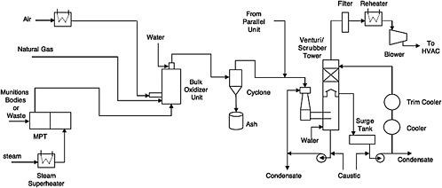
FIGURE 5-1 Flow diagram for OTM system. The offgas flow from the ANRs and the ANR hydrolysate storage tanks is not shown on this diagram. SOURCE: Adapted from the Bechtel Parsons Blue Grass Team responses on May 2, 2005, to committee questions of April 25, 2005.
Offgas leaving the MPTs flows to a flameless bulk oxidizer, where heated air and natural gas are mixed with the offgas to ensure oxidation of volatile and semivolatile organic compounds in the bulk oxidizer effluent.4 The bulk oxidizer unit operates at 2000°F, with a gas residence time of 1 second to ensure the oxidation of all organics and hydrogen and to destroy any agent present. The bulk oxidizer uses staged injection of raw natural gas, as needed, into the unit to increase the heating value of the gas stream and to maintain the bulk oxidizer at 2000°F when organic content in the gas stream is not sufficient.
The bulk oxidizer discharge stream is cooled to 1200°F by injecting atomized process water into the outlet at the top of the bulk oxidizer. This cooling eliminates or minimizes the need for refractory in the discharge pipes. The cooled gas then flows through a cyclone separator to remove particulates. There is one cyclone for each MPT offgas treatment train. The design and efficiency of this cyclone had not been identified at the time this report was being prepared. The cyclone discharges collected particulates into a drum. Since it cannot be guaranteed that the collected particulates, such as paint and rust particles from projectiles, have undergone decontamination to make them suitable for unrestricted release, they will be periodically fed back to the MPT.
Offgas leaving the cyclones is then combined with offgas from the agent neutralization reactors (ANRs) and agent hydrolysate storage tanks and fed to the venturi/scrubber tower system. This system consists of a venturi, a venturi recirculation pump, a scrubber tower, a scrubber recirculation pump, a surge drum, and two cascading coolers on the scrubber liquid recirculation line. The venturi/scrubber tower system provides quick quenching (0.3 seconds), caustic scrubbing of the acidic gases, and additional cooling of the gases to no more than 100°F. The two cascading coolers provide cooling for the venturi/scrubber tower liquids; the first cooler will cool the scrubber recirculation liquid to 100°F using cool water as the cooling medium, while the second cooler will cool the liquid to 70°F using chilled water as the cooling medium.
The scrubber overhead gases then pass through an offgas filter to remove any particulate matter over 0.5 microns in size. The particulate size is still under evaluation. The filtered gas is then heated in an electric heater to 120°F to ensure a gas relative humidity of less than 55 percent to keep it from condensing on its way through the blowers to the MDB HVAC system.
|
4 |
The OTM systems and the OTE system (for energetics offgas treatment described in Chapter 4) both include a bulk oxidizer unit, but these respective units operate at different temperatures and residence times. |
After start-up, additional scrubber liquid will be generated by condensation of the water in the incoming offgas stream. The liquid condensate generated in the scrubber tower is collected in the surge tank. It is monitored for pH and the presence of agent. Caustic solution is used to maintain the pH in the 7 to 10 range. If no agent is detected above the method detection limit, the “cleared” condensate is sent to an agent hydrolysate storage tank. If agent is detected above the method detection limit, the condensate is sent to the ANRs.
Finding 5-6. While operating conditions have been specified for the flameless bulk oxidizer unit for each MPT, details of the design were not provided. Thus, the committee could not judge whether the bulk oxidizer selected was adequate for heating the expected MPT offgas stream.
Recommendation 5-6. The bulk oxidizer unit design needs to be resolved as quickly as possible to assure that all necessary supporting equipment is identified and that the MDB footprint can accommodate the resulting OTM system.
Finding 5-7. The MPT offgas composition when treating secondary waste and closure waste streams has not been thoroughly characterized. Therefore, it is not possible to specify the level of particulate removal required to prevent excessive plugging of the bulk oxidizer and other downstream equipment.
Recommendation 5-7. Additional tests of the MPT should be performed, and representative ranges of MPT feed compositions based on all waste streams should be characterized and used to develop the data needed to specify particulate loading of the MPT offgas and bulk oxidizer performance, as well as the performance of other downstream equipment.
HEATED DISCHARGE CONVEYOR
Solid residues from the energetic batch hydrolyzer units will be transported through an HDC. The residues will be heated to at least 1000°F for 15 minutes and then cooled and stored for eventual disposal. The HDC unit planned for BGCAPP is very similar to that for PCAPP. One important difference in terms of operations, however, is that the BGCAPP unit will have to handle a large volume of fiberglass firing tubes when treating rockets. The Bechtel Parsons Blue Grass Team noted that pyrolysis (thermal decomposition) of these tubes in the HDC will produce large quantities of glass fibers in addition to tars and soot from the thermal destruction of epoxy resins (Bechtel Parsons, 2003).
Finding 5-8. The Bechtel Parsons Blue Grass team was planning to rely on tests of the HDC to be conducted for PCAPP at Pasco, but those tests were delayed and did not include processing of fiberglass firing tubes.
Recommendation 5-8. All of the testing for the HDC, including the processing of fiberglass firing tubes, should be performed as part of the program of technical risk reduction for BGCAPP.
SECONDARY WASTES
The Bechtel Parsons BGCAPP team has developed a matrix of secondary wastes expected to be generated during the agent destruction campaign or during dismantlement for closure. The matrix contained 79 types of materials as of December 17, 2004. Bechtel Parsons is in the process of identifying treatment methods for each waste stream. The options being considered include off-site disposal, MPT processing, or dunnage shredding and handling (DSH) followed by SCWO. Table 5-3 lists the general types of wastes that will need to be managed.
The secondary waste matrix lists the MPT as the treatment method of choice for almost all of the contaminated or unknown wastes produced as part of the closure operations. DSH followed by SCWO is the treatment method listed for many of the same wastes as those produced as part of the normal chemical weapons destruction campaigns. Table 5-1 shows the wastes and treatment methods.
Bechtel Parsons has conducted thermal modeling on the suitability of the MPT for treatment of contaminated polyvinyl chloride extension cords with copper wire cores; butyl rubber and Teflon masks, sludge, and wood wastes. The models are based on the results of thermogravimetric analysis of polymeric materials to determine weight loss as a function of pyrolysis temperature, volatilization, and char/tar residue. Bench-scale tests are planned to verify the models. Ultimately, precommissioning tests will be needed to verify the approach.
TABLE 5-3 General Types of BGCAPP Secondary Wastes to Be Managed
|
Waste Type |
Example |
|
Aqueous liquids |
Spent decontamination washdown fluids |
|
Other noncombustible liquids |
Ethylene and propylene glycols, water-based hydraulic fluids |
|
Combustible liquids |
Oil-based lubricants |
|
Combustible solids |
Filters, textiles, paper, rope, butyl boots, nitrile gloves, gaskets, tygon tubing |
|
Metallic solidsa |
Canisters, lead solder, steel gratings, and ladders |
|
Solids containing metals and organicsa |
Wire and cable, hoses |
|
Miscellaneous noncombustible solidsa |
Rubble, wallboard, glass fiber insulation, kaolin, vermiculite |
|
Unknown or mixed solidsa |
Heat tracing, filter cake, sludge |
|
aThese types of wastes, which are generated during operations and closure, will be treated in the MPT or sent to an appropriate treatment, storage, and disposal facility. SOURCE: Adapted from Bechtel Parsons Blue Grass Team response on May 7, 2005, to the committee’s request for information on February 2, 2005. |
|


