
4
Spark-Ignition Gasoline Engines
INTRODUCTION
A large majority of light-duty vehicles in the United States are powered with spark-ignition (SI) engines fueled with gasoline. Several technologies have been developed to improve the efficiency of SI engines. This chapter updates the status of various SI engine technologies described in the National Research Council report that focused on reduction of fuel consumption (NRC, 2002). As stated in Chapter 2 of the present report, the objective is to evaluate technologies that reduce fuel consumption without significantly reducing customer satisfaction—therefore, power and acceleration performance are not to be degraded. The primary focus is on technologies that can be feasibly implemented over the period to 2025.
The present study examines these SI engine technologies in the context of their incremental improvements in reducing fuel consumption, as well as the associated costs of their implementation. It also discusses the mechanisms by which fuel consumption benefits are realized along with the interactions that these technologies have with the base-engine architecture. As with the other vehicle technologies examined in this report, the committee’s estimates of incremental reduction of fuel consumption and the costs of doing so for the SI technologies presented in this chapter are based on published data from technical journals and analyses conducted by Northeast States Center for a Clean Air Future (NESCCAF), Energy and Environmental Analysis, Inc. (EEA), U.S. National Highway Traffic Safety Administration (NHTSA), U.S. Environmental Protection Agency (EPA), and other organizations. In addition, the expert judgment of committee members whose careers have focused on vehicle and power train design, development, and analysis, as well as the results of consultation with individual original equipment manufacturers (OEMs) and suppliers, were also incorporated in the estimates.
SI ENGINE EFFICIENCY FUNDAMENTALS
It is common practice to group engine-efficiency-related factors with their respective process fundamentals (i.e., thermodynamic factors, friction losses, etc.). For example, consider the basic stages of the SI engine cycle that contribute to positive work: heat released during fuel combustion, volumetric expansion, and associated heat transfer. The factors related to this process can be grouped together as the thermodynamic component. In addition, there are several processes within the engine that mitigate the positive work produced; these can be grouped as either gas exchange losses (pumping losses) or frictional losses within the engine. Further more, the engine architecture and the use of accessory/operational components (i.e., power steering, coolant, oil and fuel pumps) can be the source of additional parasitic losses. The fundamental aspects of each category of engine efficiency factors are discussed further in the following sections.
Thermodynamic Components
Thermodynamic factors include combustion interval, effective expansion ratio, and working fluid properties. In consideration of these factors there are some fundamental methods that can be used to improve efficiency, including:
-
Short combustion intervals—allow for more of the heat of combustion to undergo more expansion and thus yield an increase in positive work.
-
High compression ratios and late exhaust-valve-opening event—can be used to influence the expansion ratio in order to improve efficiency. However, these factors are constrained by other considerations.
-
High specific heat ratio of working fluid (i.e., cp/cv.)—working-fluid property of significance related to the specific heat ratio. Atmospheric air is preferred over exhaust gas as a combustion diluent thermodynamically, but exhaust emis-
-
sions after-treatment challenges limit this as an option for reducing fuel consumption.
-
Optimize timing of spark event—an important factor since this affects the countervailing variables of in-cylinder heat loss and thermodynamic losses. This is discussed in more detail below.
Maximum efficiency occurs when the two countervailing variables, heat loss and thermodynamic losses, sum to a minimum. The optimum spark timing is often referred to as minimum advance for best torque or maximum brake torque (MBT). At low to moderate speeds and medium to high loads, SI engines tend to be knock-prone, and sparktiming retardation is used to suppress the knock tendency. Spark-timing adjustments are also made to enable rapid-response idle load control to compensate for such things as AC compressor engagement. For this to be effective, idle spark timing must be substantially retarded from MBT. Retardation from MBT for either of the aforementioned reasons compromises fuel consumption.
Gas Exchange or Pumping Losses
Gas exchange or pumping losses, in the simplest terms, refer to the pressure-gradient-induced forces across the piston crown that oppose normal piston travel during the exhaust and intake strokes. The pumping loss that principally affects fuel consumption is that which occurs during the intake stroke when the cylinder pressure and the intake manifold are approximately equal. The pumping loss component that occurs during the exhaust stroke mainly affects peak power. Both of these oppose the desired work production of the engine cycle and thus are seen as internal parasitic losses, which compromise fuel efficiency.
Frictional Losses
The main source of friction losses within an SI engine are the piston and crankshaft-bearing assemblies. The majority of the piston-assembly friction comes from the ring-cylinder interface. The oil-control ring applies force against the cylinder liner during all four strokes while the compression rings only apply minor spring force but are gas-pressure loaded. Piston-assembly friction is rather complex as it constantly undergoes transitions from hydrodynamic to boundary-layer friction. Hydrodynamic piston-assembly friction predominates in the mid-stroke region while boundary-layer friction is common near the top center. Avoidance of cylinder out-of-roundness can contribute to the minimization of piston-ring-related friction. Crankshaft-bearing friction, while significant, is predominately hydrodynamic and is relatively predictable.
Engine Architecture
Engine architecture refers to the overall design of the engine, generally in terms of number of cylinders and cylinder displacement. The engine architecture can affect efficiency mainly through bore-stroke ratio effects and balance-shaft requirements.
Trends in power train packaging and power-to-weight ratios have led in-line engines to have under-square bore-stroke ratios (i.e., less than unity) while most V-configuration engines have over-square ratios. Under-square ratios tend to be favored for their high thermodynamic efficiency. This is due to the surface-area-to-volume ratio of the combustion chamber; under-square designs tend to exhibit less heat transfer and have shorter burn intervals. Over-square designs enable larger valve flow areas normalized to displacement and therefore favor power density. These interactive factors play a role in determining overall vehicle fuel efficiency.
Balance-shafts are used to satisfy vibration concerns. These balance shafts add parasitic losses, weight, and rotational inertia, and therefore have an effect on vehicle fuel efficiency. I4 engines having displacement of roughly 1.8 L or more require balance shafts to cancel the second-order shake forces. These are two counter-rotating balance shafts running at twice crankshaft speed. The 90° V6 engines typically require a single, first-order balance shaft to cancel a rotating couple. The 60° V6 and 90° V8 engines need no balance shafts. Small-displacement I3 engines have received development attention from many vehicle manufacturers. These require a single first-order balance shaft to negate a rotating couple. While low-speed high-load operation of small displacement I3 engines tends to be objectionable from a noise, vibration, and harshness (NVH) perspective, they could be seen as candidate engines for vehicles such as hybrid-electric vehicles (HEVs) where some of the objectionable operating modes could be avoided.
Parasitic Losses
Parasitic losses in and around the engine typically involve oil and coolant pumps, power steering, alternator, and balance shafts. These impose power demands and therefore affect fuel consumption. Many vehicle manufacturers have given much attention to replacing the mechanical drives for the first three of these with electric drives. Most agree that electrification of the power steering provides a measurable fuel consumption benefit under typical driving conditions. Fuel consumption benefit associated with the electrification of oil or coolant pumps is much less clear. Electrification of these functions provides control flexibility but at a lower efficiency. Claims have been made that the coolant pump can be inactive during the cold-start and warm-up period; however, consideration must be given to such things as gasket failure, bore or valve seat distortion, etc. These factors result from
local hot spots in the cooling system since much of the waste heat enters the cooling system via the exhaust ports.
Further discussion on the parasitic losses associated with these types of engine components is provided in Chapter 7 of this report.
THERMODYNAMIC FACTORS
Fast-Burn Combustion Systems
Fast-burn combustion systems are used to increase the thermodynamic efficiency of an SI engine by reducing the burn interval. This is generally achieved either by inducing increased turbulent flow in the combustion chamber or by adding multiple spark plugs to achieve rapid combustion.
Fluid-mechanical manipulation is used to increase turbulence through the creation of large-scale in-cylinder flows (swirl or tumble) during the intake stroke. The in-cylinder flows are then forced to undergo fluid-motion length-scale reduction near the end of the compression stroke due to the reduced clearance between the piston and the cylinder head. This reduction cascades the large-scale fluid motion into smaller scale motions, which increases turbulence. Increased turbulence increases the turbulent flame speed, which thereby increases the thermodynamic efficiency by allowing for reduced burn intervals and by enabling an increase in knock-limited compression ratio by 0.5 to 1.0. This decrease in burn interval increases dilution tolerance of the combustion system. Dilution tolerance is a measure of the ability of the combustion system to absorb gaseous diluents like exhaust gas. Exhaust gas is introduced by means of an exhaust-gas-recirculation (EGR) system or by a variable-valve-timing scheme that modulates exhaust-gas retention without incurring unacceptable increases in combustion variability on a cycle-by-cycle basis. Combustion variability must be controlled to yield acceptable drivability and exhaust emissions performance.
Multiple spark plugs are sometimes used to achieve rapid combustion where fluid-mechanical means are impractical. Here, multiple flame fronts shorten the flame propagation distance and thus reduce the burn interval. High dilution-tolerant combustion systems can accept large dosages of EGR, thereby reducing pumping losses while maintaining thermodynamic efficiency at acceptable levels.
Fuel Consumption Benefit and Cost of Fast-Burn Combustion Systems
Combining fast-burn and strategic EGR usage typically decreases fuel consumption by 2 to 3 percent, based on manufacturer’s input. The implementation of this technology is essentially cost neutral. Variable mixture-motion devices, which may throttle one inlet port in a four-valve engine to increase inlet swirl and in-cylinder mixture momentum, may add another 1 to 2 percent benefit at a cost of $50, $80, and $100 for I4, V6, and V8 engines, respectively, based on manufacturer’s input. As of 2007 the implementation of this technology has become common; therefore, fast burn and strategic EGR is considered to be included in the baseline of this analysis.
Variable Compression Ratio
If an engine’s compression ratio could be adjusted to near the knock-limited value over the operating range, significant fuel economy gains could be realized. Many mechanisms to realize variable compression ratios have been proposed in the literature and many have been tested. However, to date all these attempts add too much weight, friction, and parasitic load as well as significant cost and have therefore not been implemented into production designs (Wirbeleit et al., 1990; Pischinger et al., 2001; Tanaka et al., 2007). It should be recalled that alterations to the effective compression ratio via intake-valve closing (IVC) timing adjustments with higher-than-normal geometric compression ratios achieves some of this benefit.
VALVE-EVENT MODULATION OF GAS-EXCHANGE PROCESSES
Alteration of valve timing can have a major impact on volumetric efficiency over an engine’s speed range, and thus peak torque and power are affected by this. IVC timing is the main determinant of this effect (Tuttle, 1980). Early IVC (compression stroke) favors torque, and later IVC favors power. Implementations of valve-event modulation (VEM) typically are referred to as specific technologies such as variable valve timing, variable valve timing and lift, two-step cam phasing, three-step cam phasing, and intake-valve throttling. VEM aids fuel consumption reduction by means of reducing pumping loss. Pumping loss is reduced by either allowing a portion of the fresh charge to be pushed back into the intake system (late IVC during the compression stroke) or by allowing only a small amount of the mixture to enter the cylinder (early IVC during the intake stroke).
It should be noted that any of the VEM schemes that reduce or eliminate the pumping loss also reduce or eliminate intake-manifold vacuum. Alternative means to operate power brakes, fuel vapor canister purge, and positive crankcase ventilation (PCV) systems, normally driven by intake-manifold vacuum, must then be considered. To overcome this issue, an electrically operated pump may need to be added. It should also be noted that while the implementation of VEM techniques can boost torque output of a given engine, this report assumes that constant torque will be maintained, leading to engine downsizing. The fuel consumption benefits listed in the following section consider a constant-torque engine.
VEM History
The first modern successful production implementation of a varying valve-event setup was Honda’s VTEC in the late 1980s. Honda’s system allowed a stepped increase in the duration and lift of the intake valves. Prior to the development of a multi-step cam profile system, a cam profile was chosen based on performance compromises. Engineers were confronted with a tradeoff, as it is difficult to satisfy the needs of both good low-speed torque and high-speed torque with a single cam profile. The cam profiles and timings necessary to maximize these needs are completely different in their characteristics.
Honda’s technology was one of the first discrete variable valve lift (DVVL)-type systems. Over the years, many other companies have developed various implementations of DVVL-type setups, as well as other innovative VEM technologies. Some newer developments in VEM technology include systems that offer continuously variable lift and duration. Nissan’s VEL, BMW’s Valvetronic, and Fiat’s Multi-Air are all examples of continuously variable lift systems that also incorporate adjustable valve timing (Takemura et al., 2001; Flierl and Kluting, 2000; Bernard et al., 2002). These systems attempt to operate throttle-less and rely on varying lift and timing to throttle the incoming air. Throttle-less operation allows a reduction in pumping losses at part load, and thus reduces fuel consumption. However, these throttle-less approaches also generally result in slight variations in the very small valve lifts necessary for idle operation even with well-controlled manufacturing tolerances. These small variations result in a slightly different charge mass from cylinder to cylinder, causing somewhat rougher idle engine operation, which is detrimental to customer satisfaction.
The cam phaser, used to vary the valve timing, is another technology that has been in constant development by the OEMs. Early cam phasers featured only two-step phasing, allowing two possible cam positions relative to the crankshaft. Today, cam phasing is fully variable, offering a wide range of positions. Due to the system’s relative simplicity and long evolution, many production vehicles now utilize cam phasing technology. Until recently, cam phasing had only been applied to overhead cam style setups due to ease of integration. This recently has changed with GM’s development and production of an in-block cam phaser applied to its overhead valve (OHV) 6.2-L engine.
Intake-Valve Closing Timing
Intake-valve closing timing, also known as intake cam phasing (ICP), is a form of VEM. At moderate speeds and light loads, late intake valve closing (i.e., during the compression stroke) can reduce the pumping loss; however, it also slows combustion. Typically this configuration yields effective compression ratios that are lower than the effective expansion ratio. To achieve a lower effective compression ratio, the intake valve closing is delayed until later on the compression stroke at light loads. By closing the valve later on the compression stroke, a larger portion of the air that was drawn in on the intake stroke is pushed back out through the valve. This phenomenon allows a decrease in pumping losses by relying on the timing of the intake valve to regulate engine load. From the reduction in pumping losses, a reduction in fuel consumption will occur. Some refer to late IVC as the Atkinson cycle (Boggs et al., 1995), and most engines have some of this character. For boosted engines, late IVC is termed by some as the Miller cycle (Hitomi et al., 1995).
A diagram of a typical oil-actuated variable cam phaser system installed on the intake cam (exhaust cam timing for this engine is fixed), Figure 4.1 shows the complexity of integrating a variable cam phaser into the standard engine architecture with fixed timing. As indicated in the figure, two separate oil passages are fed to the phaser. A solenoid controls the direction of the fluid to the two different passages. These passages are used to control whether the cam will be advanced or retarded relative to the crankshaft. In order for the engine control unit (ECU) to sense the relative position of the camshaft, a position sensor is installed that provides feedback information to the ECU. It is important to note that, like many of the vehicle technologies discussed in this chapter, implementing a variable cam phaser involves a complete system integration as illustrated in Figure 4.1 and is not as simple as bolting on a component.
Fuel Consumption Benefit and Cost of IVC Timing
OEM input suggests intake cam phasing results in roughly a 1 to 2 percent fuel consumption reduction. Both the EPA and NESCCAF also estimate approximately 1 to 2 percent fuel consumption reduction (EPA, 2008; NESCCAF, 2004). EEA claims a fuel consumption improvement of 1.1 to 1.7 percent can occur with the addition of an ICP (EEA, 2007). In agreement with most sources, the committee has also estimated a 1 to 2 percent reduction in fuel consumption using ICP. However, as with the other VEM technologies that are listed in the chapter, a generalized statement can be made that smaller-cylinder-count engines (i.e., four cylinders) will be closer to the low end of this improvement range, and higher-cylinder-count engines will be closer to the high end of the fuel consumption reduction ranges that are listed.
OEM input suggests that fixed-duration intake systems add a cost of about $35/phaser. OEM input does not reflect a retail price equivalent (RPE) factor. The EPA estimates an RPE cost increase of $59/phaser (EPA, 2008). NESCCAF quoted a literature RPE of $18 to $70 (NESCCAF, 2004) and EEA estimates an RPE of $52/phaser (EEA, 2007). A 1.5 RPE factor was used to develop the committee estimate of $52.50 for an in-line engine and $105 for a V-configuration that requires two phasers.
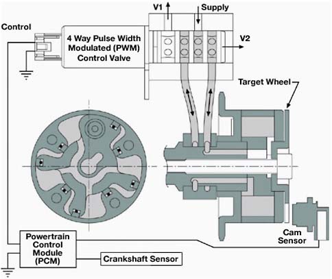
FIGURE 4.1 System-level mechanization of the variable cam phaser, oil control valve, control module, crank sensor, and cam sensor to the engine. SOURCE: Delphi (2009). Reprinted by permission from Delphi Corporation.
Valve Overlap Control
Valve overlap control, also known as dual cam phasing (DCP), is another form of VEM. Valve overlap (i.e., the interval between intake-valve opening [IVO] and exhaust-valve closing [EVC]) can affect residual-gas retention at low loads and can reduce pumping loss in a manner similar to that with EGR (exhaust gas recirculation). Valve overlap control can also be utilized to tune performance at high engine speeds, resulting in increased torque, which, in principle, can allow for minor engine downsizing. Valve overlap can be modulated by changing the phasing of either the intake or exhaust cam. Typically it is done with the exhaust cam because exhaust-cam phasing for increased overlap also delays exhaust-valve opening (EVO) timing. Thus both EVO and EVC move in ways favorable to low-speed and light-load fuel consumption reduction. Modulating valve overlap with an intake cam yields countervailing effects, i.e., increased valve overlap in this manner tends to reduce pumping loss while the corresponding IVC event will occur earlier, thus offsetting some of the increased-overlap benefit. At idle, too much valve overlap will destabilize combustion. When variable phasing, fixed-duration intake and exhaust cams are implemented, valve-overlap control may eliminate the need for an external EGR system.
Fuel Consumption Benefit and Cost of Valve Overlap Control
The fuel consumption reduction from valve overlap control/DCP is expected to be slightly greater than just controlling the IVC timing at about 2 percent over intake phasing alone, based on manufacturer input. The EPA and NESCCAF both estimate a reduction in consumption of 2 to 4 percent (EPA, 2008; NESCCAF, 2004). EEA estimates a 1.8 to 2.6 percent improvement in fuel economy (EEA, 2007). The committee concluded that adding variable exhaust cam phasing to ICP will yield an incremental 1.5 to 3 percent reduction in fuel consumption. This would mean the total estimated effect of adding DCP would be about 2.5 to 5 percent over an engine without any variable valve timing technology. The high end of 5 percent has been verified by OEMs and Ricardo, Inc.’s full-vehicle system simulation (FSS) (Ricardo, Inc., 2008).
Dual overhead cam (DOHC) V-engines with variable intake and exhaust would require four cam phasers, adding roughly $140 of manufacturer cost based on manufacturer input, but a portion of this is offset by the elimination of the external EGR system. EEA estimates an RPE of $76 to $84 for an I4, and $178 to $190 for V6 and V8 engines (EEA, 2007). The EPA estimates an incremental cost increase of $89 for an I4 and $209 for V6 and V8 engines (EPA, 2008).
NESCCAF quotes a literature RPE of $35 to $140 for dual cam phasers (NESCCAF, 2004). Discussion with OEMs also verified that by simply doubling the cost of ICP, a reasonably accurate DCP cost can be attained. The committee has estimated an RPE cost of $52.50 for an in-line engine and $105 for a V-configuration, incremental to the cost of ICP technology.
Intake-Valve Throttling
Using very short duration and low-lift intake-valve-opening events during the intake stroke can reduce (or eliminate) the pumping loss. This VEM, also known as intake-valve throttling, also tends to slow combustion, mainly at low engine speeds. (Small-scale turbulence generated by this approach dissipates rapidly, well before the start of combustion, and thus this does not generally contribute to rapid combustion). Note that low valve lift is simply a consequence of short-duration cam design. Manufacturing tolerance control is of extreme importance with intake valve throttling if cylinder-to-cylinder variability at idle is to be acceptable. BMW and Nissan currently offer this technology on some of their engine models, which use varying lift and timing to throttle the engine. Other manufacturers have announced plans to introduce engines with throttle-less operation within the next few years.
The above options (DCP and ICP) are focused mainly on pumping-loss reduction by means of late IVC timing and exhaust-gas recycling via variable valve overlap. Very early IVC (i.e., during the intake stroke) is another effective means of reducing pumping losses, but it involves much more complex and costly means of implementation. Two types of intake-valve-opening techniques are considered: discrete variable valve lift and continuously variable valve lift.
Discrete Variable Valve Lift
A discrete variable valve lift (DVVL) system is one which typically uses two or three different cam profiles over the range of engine speeds and loads. This system attempts to reduce pumping losses by varying the lift profile of the camshaft. By varying the lift of the valves, it is possible to limit the use of the throttle and significantly reduce the pumping losses.
As described earlier, Honda has been using a DVVL-type setup on its vehicles known as VTEC. To engage the different cam profile on Honda’s system, there is a third cam lobe and follower, located in between the two main lobes, which is hydraulically activated by an internal solenoid controlled oil passage. During low-speed and low-load operation, the engine runs using the base cam profile(s). Once a certain load point is reached, the ECU activates a control valve to direct oil pressure from the main gallery to an oil passage that engages the third follower. Once the third follower engages, it is then locked into place by a locking pin. Honda’s VTEC system is more cost-effective on its single overhead cam (SOHC) engines, due simply to the fact that a DOHC engine would require more hardware. This is an example of one manufacturer’s method of DVVL implementation. It should be noted that other manufacturers have developed different designs to accomplish the same goal, and as a result the different systems have differing amounts of pumping loss reduction and friction increase. This situation reinforces the point that advanced VEM technologies are not simply “bolton” parts that provide a uniform fuel consumption reduction to all OEMs.
Delphi performed testing on a GM 4.2-L I6 equipped with a two-step variable valve actuation system and a camshaft phaser on the intake (Sellnau et al., 2006). The engine was already outfitted with an exhaust cam phaser. Delphi’s two-step valve actuation system consisted of oil-actuated switchable rocker arms. Testing on the engine revealed a 4.3 percent fuel consumption reduction during the EPA city drive cycle, compared to the base engine with no variable lift and timing. These results were obtained with no other modifications besides the VVL, a phaser, and control system reconfiguration. Delphi claimed that “mixture motion is nearly absent for low lift profiles, so an enhanced combustion system, with higher tumble for low-lift profiles, would likely yield significant improvements in fuel economy.” In the second portion of the test Delphi modified the cylinder head and added flow restriction that generates turbulence in an attempt to speed up combustion, thereby furthering the fuel economy gain. Chamber masks were used to increase the tumble motion. The lift profile on the exhaust cam and the port were also modified. For the second phase of testing with the altered cylinder head and calibration, the fuel consumption reduction was estimated to be 6.5 percent in comparison to the original engine. These values were estimated from data taken at multiple load points rather than over a driving cycle (Sellnau et al., 2006).
Fuel Consumption Reduction and Cost of DVVL
Two (or three)-step cams that yield short intake durations using DVVL can yield fuel consumption reductions in the 4 to 5 percent range based on vehicle OEM input. A reduction of 3 to 4 percent in fuel consumption (FC) is estimated from the EPA (EPA, 2008). FEV has developed a two-stage switch of the intake valve lift that is claimed to offer up to a 6 to 8 percent reduction in consumption when combined with variable valve timing, during the New European Drive Cycle (Ademes et al., 2005). NESCCAF and EEA estimate that a 3 to 4 percent reduction is possible (NESCCAF, 2004; EEA, 2007) on the U.S. driving cycles. EEA also estimates a fuel economy improvement of 7.4 to 8.8 percent when DVVL is combined with DCP and the engine is downsized to maintain constant torque. Simulation work by Sierra Research indicated a 6.3 to 6.8 percent benefit when combined with variable valve timing, which accounts for up to 5 percent of that
amount (Sierra Research, 2008). The committee concluded that a 1.5 to 4.0 percent drive-cycle-based FC reduction is possible, incremental to an OHC engine with DCP or an OHV engine with CCP.
Vehicle OEM input suggests a $35 to $40/cylinder cost for implementing DVVL. The Martec Group estimates an OEM cost of $320 to implement a two-step VVL on a V6 DOHC engine (Martec Group, Inc., 2008). The EPA estimates an incremental cost increase of $169 for an I4, $246 for a V6, and $322 for a V8 (EPA, 2008). EEA estimates RPEs for an OHC-4V; $142 to $158 (equivalent to $95 to $105 assuming an RPE multiplier of 1.5) for an I4, $188 to $212 (equivalent to $125 to $141 assuming an RPE multiplier of 1.5) for a V6, and $255 to $285 (equivalent to $170 to $190 assuming an RPE multiplier of 1.5) for a V8 (EEA, 2007). The committee estimates the manufacturing cost of implementing DVVL to be about $30 to $40/cylinder.
Continuously Variable Valve Lift
The continuously variable valve lift (CVVL) system allows a wide control range of the camshaft profile (see Figures 4.2 and 4.3 for schematics). A continuous system allows for calibration of the optimal valve lift for various load conditions, versus the discrete system, which will only offer two or three different profiles. The combination of a continuous VVL system and an intake cam phaser has the potential to allow the engine to operate throttle-less. In the following, greater detail of this particular VEM technology is given due
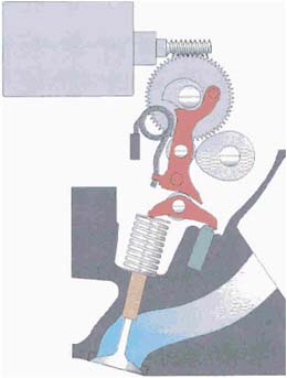
FIGURE 4.2 BMW Valvetronic. SOURCE: Flierl et al. (2006). Reprinted with permission from SAE Paper 2006-01-0223, Copyright 2006 SAE International.
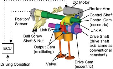
FIGURE 4.3 Nissan valve event and lift design. SOURCE: Takemura et al. (2001). Reprinted with permission from SAE Paper 2001-01-0243, Copyright 2001 SAE International.
to its relative novelty to the mass production environment and the large fuel consumption benefits it offers. Two approaches to CVVL have been considered, electromechanical and electrohydraulic.
Electromechanical CVVL Systems
BMW was the first to offer a mass production fully variable valve train incorporating CVVL in 2001, which it calls Valvetronic, Figure 4.2. This system is an electromechanical system that when combined with variable intake and exhaust cam phasers provides a fully throttle-less induction system. To vary the lift of the valve, an intermediate lever was added along with an eccentric shaft. The eccentric shaft is operated by an electric motor that adjusts the positioning of the lever over the camshaft. The lever contains a profile with one side being relatively flat and the other side being relatively steep. Adjusting the relative positioning of the lever controls the valve lift. BMW claims that up to a 10 percent reduction in fuel consumption is possible with this system (Sycomoreen). Figure 4.2 shows the many added components needed for the Valvetronic system.
Nissan Motor Company has also developed a continuous variable valve event and lift (VEL) system (Figure 4.3). The electromechanical system allows continuous variation of valve timing and lift events similar to the BMW system, but achieves this using a different architecture. Nissan estimates a 10 percent reduction in fuel consumption over the Japanese 10-15 drive cycle (Takemura et al., 2001) for its VEL system. The 10-15 drive cycle is intended to simulate a typical urban drive cycle, and an EPA combined FTP cycle rating would be somewhat lower. Nissan attributes the reduction in consumption to “lower friction loss due to the use of extremely small valve lift-timing events and reduction of pumping loss resulting from effective use of internal gas recirculation.” Nissan evaluated the consumption benefits distribution at a
fixed speed and load of 1,600 rpm and 78 N-m. The distribution of effects was the following: (1) pumping loss decrease yielded a consumption reduction of 5.2 percent, (2) friction reduction yielded a consumption benefit of 1.1 percent, and (3) an improvement in combustion caused a reduction in consumption of 3 percent.
Figure 4.3 shows the layout of Nissan’s VEL system. The electromechanical system uses an oscillating cam to open and close the valve. An oscillating cam (output cam) looks like half of a camshaft, but it is hinged on one end to allow full opening and closing of the valve on the same cam face. To change the valve lift and duration of the cam, the control shaft is adjusted by a motor to change the distance between the control cam and the oscillating cam. An increase in distance is caused by the lobe on the control shaft turning and pushing the rocker arm assembly out. This changes which portion of the output cam contacts the valve to control the amount of lift.
Toyota Motor Company has recently developed its own type of a CVVL timing system. The new system will first be applied to their newly developed 2.0-L engine. Toyota’s system features separate cam phasers on the intake and exhaust camshafts to vary the camshaft timing, along with a continuously variable valve lift system. Toyota claims that the system “improves fuel efficiency by 5 to 10 percent (depending on driving conditions), boosts output by at least 10 percent and enhances acceleration.” Toyota did not state what features the base engine already had in order to generate fuel efficiency improvement percentages (Toyota Motor Co., 2007).
The Technical University of Kaiserslautern performed testing on a 2.0-L four-cylinder gasoline engine that was outfitted with a fully variable lift and timing system (VVTL) called Univalve, Figure 4.4. The Univalve system allows for either the use of standard throttle or unthrottled operation. At a load point of 2000 rpm and a BMEP of 2 bar, a 13 percent reduction in fuel consumption occurred compared to the base engine with a nonvariable valve train. This reduction is due to the reduction in the pumping work and an improvement in the formation of the mixture. The Univalve system varies the lift and duration of the valve by adjusting the eccentric contour (see Figure 4.4). Adjusting the eccentric shaft changes the rocker arm pivot point (Flierl et al., 2006).
The Univalve system in Figure 4.4 operates similar to BMW’s version of a CVVL system. In Figure 4.4 the image to the left demonstrates a fixed pivot ratio on the rocker with constant valve lift. The image to the right features variable valve lift. To vary the lift the rocker arm is no longer fixed to a single pivot point. An eccentric shaft creates a varying pivot point by adjustment of the shaft’s contour contact point on the rocker.
Honda has also patented its new Advanced-VTEC system, which turns its current DVVL VTEC system into a throttleless CVVL setup. While initial claims are up to a 10.5 percent reduction in fuel consumption, this system is not currently in
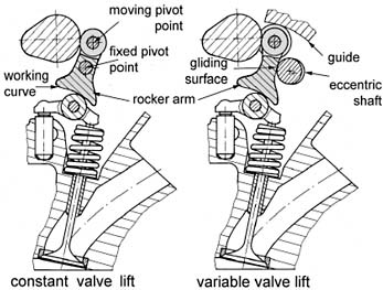
FIGURE 4.4 Univalve. SOURCE: Flierl et al. (2006). Reprinted with permission from SAE Paper 2006-01-0223, Copyright 2006 SAE International.
production and the testing cycle used to produce this estimate is unclear. Therefore, Advanced-VTEC is only mentioned to demonstrate an example of emerging CVVL technology.
Electrohydraulic CVVL Systems
The electrohydraulic approach to CVVL has been under development for over a decade. One of the organizations which has been active in this development is Fiat Central Research (CRF). The major focus of the work by CRF is a system that it calls Uniair (Bernard et al., 2002). Fiat recently announced a system it calls Multiair that is derived from Uniair. Multiair is a joint development between Fiat and valve train component supplier INA that promises a 10 percent reduction in fuel consumption. Other organizations have also been active in the development of systems using similar principles (Misovec et al., 1999). The Uniair/Multiair system has been described as a lost-motion system wherein the camshaft lobe drives the piston of a small pumping chamber, one for each cylinder intake and one for each exhaust. Multiair utilizes the system only for the intake valves.
The output from the pump is controlled by a solenoid-actuated flow control valve that directs the hydraulic output of the pump directly to the hydraulic actuator on the valve(s) or to the accumulator. If the control valve directs the hydraulic pressure to the valve actuator(s), the valve(s) open normally following the camshaft profile. In principle a lost-motion system allows opening the valve(s) at any fraction of the normal valve lift profile by directing part of the hydraulic pressure to the accumulator rather than to the valve actuator. By appropriately controlling the application of the hydraulic pressure to the valve actuators or to the accumulator, a wide range of valve lift profiles can be achieved, including mul-
tiple small lifts during one valve event. This latter capability is not achievable with mechanical CVVL systems. However, electrohydraulic CVVL systems tend to be less efficient considering the energy lost by the hydraulic pump and the increased friction losses from the additional number of components. The committee believes that the large increase in parasitic losses that will offset the perceived fuel consumption reduction benefit, combined with the high component cost, will limit the market penetration of this technology. In addition, achieving consistent and uniform valve lifts under idle conditions to maintain a smooth idle may be more challenging than with mechanical CVVL systems.
Fuel Consumption Benefit and Cost of CVVL
The above discussion reviewed the technology of VEM approaches and various FC benefits ascribed to each system. As noted in Chapter 2, the fuel consumption reduction benefits for the technology approaches considered are based on the combined city and highway driving cycles, while some of the benefits described earlier are not necessarily based on these driving cycles. CVVL is expected to be in the 5 to 7 percent range based on manufacturer input. The EPA and NESCCAF both estimate a 4 to 6 percent reduction in fuel consumption (EPA, 2008; NESCCAF, 2004), while EEA estimates a 6.5 to 8.3 percent reduction in fuel consumption at constant engine size and 8.1 to 10.1 percent with an engine downsize to maintain constant performance (EEA, 2007). Sierra Research’s simulation work resulted in a 10.2 to 11.0 percent benefit when combined with variable valve timing (Sierra Research, 2008). The committee has estimated that CVVL will have an additional 3.5 to 6.5 percent reduction in fuel consumption over an engine already equipped with DCP. Going from a base DOHC engine to one with continuously variable lift and timing could provide a 6 to 11 percent fuel consumption reduction assuming engine size adjustments for constant acceleration performance.
Vehicle OEM input suggests that the cost of a continuously variable intake-valve is two to three times that of the two-step system plus the cost of the actuation system ($40 to $80) plus the cost of the intake and exhaust cam-phasing system. Vehicle integration could add another cost in the range of $140. The EPA estimates an RPE incremental cost of $254 (or $169 cost assuming an RPE multiplier of 1.5) for I4, $466 (or $311 cost) for V6, and $508 (or $339 cost) for V8 engines (EPA, 2008). The Martec Group estimates a manufacturing cost of $285 for an I4, $450 for a V6, and $550 for a V8 (Martec Group, Inc., 2008). For a CVVL system, EEA (2007) estimates RPEs of $314 to $346 (or $209 to $231 cost) for an I4, $440 to $480 (or $293 to $320 cost) for a V6, and $575 to $625 (or $383 to $417 cost) for a V8 (EEA, 2007), all assuming an RPE multiplier of 1.5. The committee estimates the manufacturing cost of CVVL to be $159 to $205 for I4 engines, $290 to $310 for V6 engines, and $350 to $390 for V8 engines, not including an RPE factor.
VEM Implementation Techniques
Many of the above-mentioned VEM systems are often implemented as a package combining varying valve lift and timing events. The combination of these technologies will provide further reduction in the use of the throttle.
General Motors Research and Development (Kuwahara et al., 2000; Cleary and Silvas, 2007) performed testing on a single-cylinder model of their 3.4-L DOHC engine. The model made use of varying intake valve cam timing, duration, and intake valve lift. A combination of the varying parameters allowed for the engine to operate without a throttle. From the study by General Motors, an approximate reduction in fuel consumption of up to 7 percent occurred at part load conditions. By unthrottling the engine, a large reduction in throttling losses occurs and the engine was able to operate at higher intake manifold pressures. It is important to note that the cost and fuel consumption reductions of the various VEM approaches are highly variable and dependent upon the basic engine architecture to which they are applied.
Cylinder Deactivation
Cylinder deactivation is utilized during part load situations to reduce thermal and throttling losses. During constant speed operation, the power demand is relatively low. By shutting off multiple cylinders, a higher load is placed on the remaining operating cylinders. The higher load requires the throttle to be open further and therefore reduces the throttling losses. The decrease in losses reduces the overall fuel consumption. Cylinder deactivation via valve deactivation has been applied to four-, six-, and eight-cylinder engines, in some cases rather successfully. Most commonly, cylinder deactivation is applied to engines that have at least six cylinders; four-cylinder engines typically are not equipped with deactivation due to additional noise, vibration, and harshness concerns that are deemed unsatisfactory for consumers. Even current production V6 offerings have NVH levels that are very noticeable to customers. Increased NVH can be perceived as a low-quality characteristic that deters potential customers from purchasing vehicles with this technology.
History of Cylinder Deactivation
Cylinder deactivation was first implemented on a production vehicle in 1981 on the Cadillac V8-6-4. The engine could operate in four-, six-, and eight-cylinder mode depending on power demand. To deactivate the cylinders, a solenoid mounted on top of the rocker arm assembly would disconnect the pivot point for the rocker and the rocker would then pivot against a soft spring. The valves would remain closed and the cylinder would not fire, but rather act as a compressed air spring. This system helped to reduce fuel consumption at cruising type conditions. However, drivability and the need
for quick re-engagement of the cylinders caused customer dissatisfaction, and the technology was soon taken out of production. Since then, engine control systems and programming ability have diminished the drivability concerns with modern day deactivation systems. New solutions have been developed to address the NVH concerns that arise when cylinders become deactivated. The NVH is a concern during deactivation due to the “lower frequency, higher amplitude torque pulsations at the crankshaft” (Leone and Pozar, 2001). With the addition of active engine mounts, any vibrations which would normally transfer to the passenger compartment of the vehicle, causing customer dissatisfaction, are nearly eliminated. However, active engine mounts add cost. Today’s trend toward overhead cam (OHC) valve trains has an added a level of cost and complexity to integrate cylinder deactivation.
Implementation of Cylinder Deactivation
The integration of a cylinder deactivation system varies depending on the engine layout. For overhead valve V8 and V6 engines, this can be accomplished fairly simply by modifications to the passages that supply oil to the valve lifters along with different valve lifters (Falkowski et al., 2006). Implementation of a deactivation system on an OHC engine is slightly different than on an OHV engine. One of the methods utilized for cylinder deactivation in an OHC roller finger follower system involves the use of a switchable roller finger follower. In the follower’s normal mode, the valve will operate as usual and maximum lift will still be achieved. To deactivate the cylinder, a locking mechanism must be released on the follower by oil pressure (Rebbert et al., 2008), collapsing the follower and rendering the valve inactive.
Fuel Consumption Benefit and Cost of Cylinder Deactivation
Vehicle OEMs estimate cylinder deactivation typically yields fuel consumption reductions in the 6 to 10 percent range on V8 configurations. Testing done by FEV on a V8 engine found that a decrease in fuel consumption of 7 percent occurred on the New European Drive Cycle (NEDC). According to FEV, these reductions would be “even higher for the US driving cycle, because of the US cycle’s higher proportion of part load operating conditions” (Rebbert et al., 2008). NESCCAF estimates a 4 to 6 percent reduction in fuel consumption (NESCCAF, 2004). The EPA estimates a 6 percent reduction in fuel consumption (EPA, 2008). Sierra Research’s simulation estimated a reduction in consumption of 7.5 to 8.8 percent (Sierra Research, 2008). EEA estimates a 5.3 to 7.1 percent reduction in fuel consumption (EEA, 2007). For OHV engines, the committee estimates a 4 to 6 percent drive-cycle fuel consumption reduction on a V6, and a 5 to 10 percent reduction on a V8. For OHC engines, the committee assumes manufacturers would have already implemented DCP and VVL based on the cost/benefit ratio. This means that there is less pumping loss left to reduce, resulting in an incremental 1 to 2.5 percent reduction for a V6 and a 1.5 to 4 percent reduction for V8 configurations. The lower cost-benefit ratio for cylinder deactivation makes the technology far less attractive on DOHC engines. Despite the existence of prototype four-cylinder engines with cylinder deactivation, the committee believes the cost and customer dissatisfaction issues related to NVH outweigh the benefits of implementing this technology on four-cylinder engines.
Vehicle OEMs estimate the cost for deactivation is approximately $115. Vehicle integration items that mitigate NVH issues may incur additional costs in the $140 range. The cost of applying cylinder deactivation to OHC engines is much higher, i.e., $340 to $400 because more complex and costly valve train elements must be changed. The EPA estimates the incremental RPE cost to be $203 (or $135 cost) for six cylinders and $229 (or $153 cost) for eight cylinders (EPA, 2008) (both assuming an RPE multiplier of 1.5). NESCCAF quotes a literature RPE of $112 to $746 (NESCCAF, 2004) (or $75 to $497 cost). Martec estimates a manufacturing cost increase of $220 for a V6 DOHC engine (Martec Group, Inc., 2008). Sierra Research estimates an incremental cost of $360 to $440 (Sierra Research, 2008). EEA (2007) estimates for six-cylinder engines an RPE of $162 to $178 (or cost of $108 to $119) with an additional cost of $140 for NVH. For eight-cylinder engines, EEA estimates an RPE of $205 to $225 (EEA, 2007) (or cost of $137 to $150 assuming an RPE of 1.5). The committee estimates that the manufacturing cost of implementing cylinder deactivation for OHV would be $220 to $255 and $340 to $420 for engines with SOHC (not including RPE).
Camless Valve Trains
A fully camless valve train eliminates the need for camshafts, as well as various other supporting hardware, and operates the valves individually by means of actuators. This would allow for VEM fuel consumption saving technologies, such as cylinder deactivation and continuously variable valve lift and timing, to be applied all in one package. However, the complexity of the controls required makes for a difficult integration. Camless valve trains are electromagnetic, hydraulic, pneumatic, or combinations of these that all face fundamental obstacles. By replacing the valve train, BMW claims the frictional saving from just the roller-bearing valve train achieves a further 2 percent reduction in fuel consumption. BMW also claims an overall reduction of up to 10 percent from camless operation (Hofmann et al., 2000). However, none of these has been shown to offer advantages not observed with the aforementioned cam-based systems. The very high valve-timing precision associated with most cam-driven systems is subject to compromise with camless approaches. The ballistic character of the valve assembly
with any camless system presents many control challenges. In addition, the power demand for camless systems is generally higher than that of their cam-driven counterparts.
Camless systems are perceived to have significant durability risk, and as a result, no production implementations of camless systems have been announced. It is the judgment of the committee that camless systems need further development and are not expected on the market before 2015.
GASOLINE DIRECT INJECTION
The most recent development of direct injection spark ignition (DISI) (also known as GDI) systems (Wurms et al., 2002) have focused on early-injection, homogeneous-charge implementations using stoichiometric mixture ratios under most operating conditions. These conditions allow for the use of highly effective and well-proven closed-loop fuel control and three-way catalyst exhaust aftertreatment systems. Fuel consumption benefits of these homogeneous versions are derived mainly from a knock-limited compression ratio increase (typically +1.0) enabled by forcing all of the fuel to vaporize in the cylinder. This yields a charge-cooling effect that suppresses the knocking tendency. Another added benefit of charge-cooling is an increase in the volumetric efficiency from the increase in density of the incoming charge. In contrast, with port fuel injection (PFI) systems some of the fuel vaporizes in the intake port, and this conveys heat from outside of the cylinder, i.e., from the intake port, to the in-cylinder charge. While heating of the intake charge is a negative (relative to the knock-limited compression ratio and performance) it does provide a measure of “thermal throttling” at typical road loads, which reduces negative pumping work. Thermal throttling, like common pressure throttling, lowers the mass of inducted fuel-air mixture thus reducing power, which is the objective of throttling. It does this, however, with less pumping loss than the conventional throttling used with homogeneous DISI.
In terms of additional losses, DISI relies on fuel pressures that are higher than those typically used with PFI systems (e.g., 150-200 bar versus 3-5 bar for PFI), and the increase in required fuel pump work increases parasitic loss. Finally, these homogeneous, stoichiometric DISI systems cannot exploit the thermodynamic expansion efficiency gains possible with lean overall mixtures.
History of Direct Injection
Early (1960s and 1970s) versions focused on late- injection, lean overall stratified-charge implementations as exemplified by the Texaco TCCS (Alperstein et al., 1974) and Ford PROCO (Simko et al., 1972) systems, neither of which entered volume production. These systems were attempts to utilize gasoline and other fuels in spark-ignited engines designed to take advantage of two of the three thermodynamic advantages of diesels, namely lack of throttling to eliminate pumping losses, and lean overall mixture ratios to achieve more thermodynamically efficient expansion processes. However, the TCCS and PROCO systems suffered from injector fouling, high exhaust emissions and low power density. Nonetheless, the goals of these engine systems remained valid and interest returned to DISI following progress in fuel-injection systems and engine controls during the 1980s and early 1990s. Mitsubishi introduced the first production implementation of DISI (which they called GDI) in Europe in 1996 (Iwamoto et al., 1997) in a 1.8-L four-cylinder engine, followed shortly after by a 3.5-L V6 in 1997. These GDI systems utilized lean-overall stratified-charge combustion but with some inlet throttling. It was soon found that typical inuse fuel consumption was significantly higher than European emissions-test-schedule results suggested.
Following an initial burst of interest, Mitsubishi GDI sales were lower than expected. Hence, this system was withdrawn from the market, and there was a return to conventional PFI systems. It was believed that this withdrawal stemmed not only from disappointing sales but also because meeting upcoming NOx emissions standards in Europe and especially the United States using only combustion system control was more difficult than anticipated, and lean NOx aftertreatment systems were seen as very costly and of questionable reliability for volume production.
Implementation of Direct Injection
A concern today (as in the past) with DISI systems is the matter of fuel-based carbonaceous deposits forming from residual fuel in the injector nozzle upon hot engine shutdown. Carbonaceous deposits can restrict fuel flow and also modify fuel-spray geometry in some unfavorable manner (Lindgren et al., 2003). Locating the injector in a relatively cool part of the cylinder head is one approach to alleviating this problem. Fuel variability in the United States is of some concern relative to this issue based largely upon the olefin content of the fuel, which typically is higher than that found in European gasoline. While some concerns with deposits remain, they are being alleviated mainly by injector design improvements.
DISI researchers often make reference to wall-guided, flow-guided, or spray-guided injection (Kuwahara et al., 2000), and in general these terms refer to different geometric arrangements of the fuel injection and mixture preparation processes. For example, wall-guided usually refers to placement of the fuel injector to the side of the cylinder near the corner of the cylinder head with the cylinder wall. The spray is then aimed across the cylinder toward the top of the piston when the piston is near the top of the cylinder. In this case the piston crown shape is the “wall” which guides the spray (Kuwahara et al., 2000). In spray-guided engines, the injector is located in the cylinder head near the center of the cylinder with the spray aimed down the cylinder axis (Schwarz et al., 2006). Injection in this case would be timed later during the induction process. The fuel-spray trajectory is then guided
mainly by the direction of the spray and its interaction with the cylinder gas motion rather than by directly impinging on a surface such as the piston.
BMW performed a fuel consumption comparison study using a four-valve port fuel injection engine with fixed timing and lift as the base engine for comparison. For the study a direct injection system operating at stoichiometric was applied to an engine, and a fuel consumption benefit of 5 percent resulted. BMW claimed that if a spray-guided system were adapted, the engine could operate with lean mixtures, which would allow for up to a 20 percent fuel consumption reduction (EEA, 2007).
Fuel Consumption Benefit and Cost of Direct Injection
The increase in knock-limited compression ratio possible for DISI configurations would be expected to yield a fuel consumption reduction in the 2 percent range based on vehicle OEM input, but the countervailing effect of pumping and parasitic loss increases may reduce this benefit somewhat to about 1.8 percent. Based on modeling by EPA, consumption reduction estimates for converting from a PFI to a DISI system are in the range of 1 to 2 percent for four-, six-, and eight-cylinder engines (EPA, 2008). Sierra Research estimates a reduction in consumption of 5.9 to 6.2 percent (Sierra Research, 2008). EEA estimates a 2.9 to 3.8 percent reduction in fuel consumption (EEA, 2007). Ricardo Inc.’s simulation work (Ricardo, Inc., 2008) attributes a 2 to 3 percent benefit to DISI. The committee believes that a 1.5 to 3 percent fuel consumption reduction can be realized from stoichiometric direct injection.
Vehicle OEMs estimate that the variable cost of DISI for parts is in the range of $60 per cylinder plus about $136 for vehicle noise abatement features, excluding the cylinder-head design and retooling costs. This input does not reflect an RPE factor. The EPA estimates the incremental cost for converting from a PFI to a DISI system on a four-cylinder engine to be from $122 to $420, on a six-cylinder from $204 to $525, and on an eight-cylinder from $228 to $525 (EPA, 2008). Martec Group estimates incremental costs of $293 for a four-cylinder, $372 for a six-cylinder, and $497 for an eight-cylinder engine (Martec Group, Inc., 2008). The estimates from Martec were based on converting to a homogeneous, side-mount direct injection from a port injection system. The committee estimates that the manufacturing cost of implementing a stoichiometric direction injection system would be $117 to $351 depending on the cylinder count (not including RPE). The cost range for noise abatement-related items causes the most uncertainty in the estimates, as the various manufacturers have different standards for acceptable noise levels. Luxury vehicles, for example, require more money to be spent to reduce noise to levels that customers expect. See Table 4.A.1 in the annex at the end of this chapter for a complete breakdown of cost and fuel consumption benefits for each engine size, including ranges for costs.
DOWNSIZED ENGINES WITH TURBOCHARGING
Turbocharging and downsizing engines (Petitjean et al., 2004) reduces engine mass and pumping losses, but the fuel consumption benefit is based somewhat on the measures taken to avoid knock and pre-ignition. Some engines in this category are developed and calibrated in such a way that premium fuel is required in order to avoid knock without decreasing the compression ratio. If this is the case, any fuel consumption benefit cannot be solely attributed to turbo-charging and downsizing. Based on vehicle OEM input, a compression-ratio reduction of 1 to 2 from non-turbocharged versions is typically required if this system is to be regular-fuel compatible. Furthermore, reduction in the number of cylinders, e.g., V6 to I4, may require countermeasures necessary to satisfy NVH expectations.
Implementation of Downsizing and Turbocharging
Several conditions must be addressed in implementing downsizing and turbocharging. Piston oil squirters aimed at the underside of the piston and oil coolers are employed to mitigate knock and pre-ignition conditions. An increase in intake air temperature is a natural by-product of compressing the air. To counter this effect, charge-air coolers are frequently employed to reduce charge temperature prior to its entry into the cylinder. In order to maximize the power output of the engine, the charge cooler acts as a heat exchanger and typically uses ambient air for cooling. The addition of a charge cooler creates packaging concerns since a location must be chosen where the cooler will experience a large amount of cross flow in order to avoid becoming heat soaked during prolonged high load conditions.
Additional parasitic loads are often imposed by the use of increased oil and coolant pump capacities relative to their non-turbocharged counterparts. The increase in capacities results from the increase in power and heat rejection with the same physical displacement.
As mentioned above, a port fuel-injected engine typically requires a decrease in compression ratio, which decreases the thermal efficiency and the part load response of a turbocharged engine. Direct injection alleviates some of the knock tendencies associated with turbocharging through the charge cooling effect created by the high atomization of the fuel that results from high injection pressure. This cooling effect allows for a less significant reduction in compression ratio compared to a port fuel-injected engine. A concern with direct injection is the injector nozzle fouling upon hot engine shutdown, as noted previously. However, a positive synergism is possible by combining DISI, turbocharging, and dual cam phasers, because under some operating conditions the intake manifold pressure is higher than that of the exhaust manifold. This positive pressure difference enables improved exhaust scavenging and thus improved volumetric efficiency. This condition is sometimes referred to as blow-through
because it occurs during valve overlap. This synergism of turbocharging, DISI, and blow-through can enable further engine downsizing, and an additional fuel consumption benefit may thus result. Unfortunately, this engine performance opportunity occurs in the knock-sensitive operating range. As a result, establishing acceptable vehicle launch performance with turbocharged and downsized engines is challenging.
The distinction between research octane number (RON) and motor octane number (MON) is particularly noteworthy when fuels other than traditional gasoline are considered. The test methodology on which RON is based reflects resistance to thermal auto-ignition resulting from both chemical and heat-of-vaporization (evaporative cooling) properties, whereas MON is relatively insensitive to the latter of these. The difference between these two metrics is termed sensitivity (RON – MON = sensitivity). When fuels like ethanol are considered, the aforementioned distinction should be emphasized as this fuel has a very high RON, but its MON is moderate. Hence, the sensitivity of ethanol is 18, whereas that of a typical gasoline is considerably lower, e.g., 10. The consequence of high-sensitivity fuels when aggressive boosting and high compression ratios are pursued is an increased vulnerability to pre-ignition problems. This typically results from engine operation in the peak-power range where all surface temperatures to which the fuel is exposed are very high. This tends to reduce the heat-of-vaporization benefit associated with ethanol. It has been widely recognized for most of the history of the SI engine that water induction along with the fuel and air can reduce the thermal auto-ignition tendency and thus can increase the torque and power output. While this has been widely used in racing communities, there are some practical limitations to the general applicability of this, e.g., water can find its way into the crankcase and form an emulsion with the oil and therefore compromise the lubrication system.
The evaporative characteristic of any liquid largely depends upon intermolecular affinity, and in the cases cited above the so-called hydrogen bonding is a major component. This involves the polarized bonds between hydrogen and oxygen atoms where there is a slight positive charge on the hydrogen atom that is bound to an adjacent oxygen atom, which carries a slight negative charge. Hence, the positive charge on the hydrogen atom of the −OH group applies an attractive force acting on the negative charge on the oxygen atom of a nearby molecule. This grouping of −OH-containing molecules, be they ethanol or water, is responsible for their relatively high evaporative-cooling characteristic. This evaporative cooling characteristic can be utilized to prevent knock at certain engine operating conditions by implementing a system that can selectively inject the charge cooling liquid. This system is discussed below in this chapter in the section “Ethanol Direct Injection.”
Exhaust-gas recirculation (EGR) is well known as a means to reduce pumping losses and thereby increase fuel efficiency. With downsized turbocharged engines (including those with direct fuel injection) it has been found that cooled EGR can be seen as an alternative means for controlling knock at moderate engine speeds and medium to high loads. Under certain operating and base-engine conditions, passing the EGR through a heat exchanger to reduce its temperature can be a more fuel-efficient means of controlling knock compared to spark-timing retardation and fuel-air ratio enrichment. The fuel consumption benefits of this feature are highly dependent upon the base engine to which it is applied and the engine’s operating map in a particular vehicle. As the heat exchanger must be equipped with a diverter valve to accommodate heat-exchanger bypass for lighter-load operation, the sequences of carbonaceous deposit formation in the heat exchanger, in the diverter and control valves, and in the turbine are among the real-world factors that can compromise the overall performance of this feature. This feature is in production for CI engines for which the exhaust particulate level is much higher than for downsized and boosted SI engines; however, packaging the system into certain vehicles can make implementation difficult.
Variable geometry turbochargers (VGTs), commonly used on CI diesel engines, have not reached mainstream use on SI engines. The concern with using VGTs on gasoline-engine exhaust has been the ability of the adjustable blades and their adjustment mechanism to withstand the higher temperatures of the gasoline exhaust gases. A diesel engine typically has lower exhaust gas temperatures, and material selection for the adjustable blades has been successful in production. Recently, Porsche and Borg Warner have developed a variable geometry turbo to be used on the Porsche 911. This turbocharger required the development of new material specifications that could withstand the higher temperatures of the exhaust gases. Due to the high cost of material to withstand the heat and ensure long-term functionality of the vane guides, VGTs are currently seen only for use in high-end vehicles. Alternatively, a downsized, fixed-geometry turbo-charger may be used, but this approach will compromise power output because the fixed exhaust turbine geometry will restrict airflow through the engine in order to provide acceptable low-speed turbocharger transient response. Extra-slippery torque converters (e.g., those with higher stall speed) can help to alleviate turbo lag issues, but they will also impose a fuel consumption penalty from increased slippage.
General Motors performed simulation testing on its 2.4-L port fuel-injected four-cylinder engine in the Chevrolet Equinox. The port fuel-injected 2.4-L engine was compared to an engine of the same displacement equipped with direct injection, turbocharger, and dual VVT. GM claims that this approach “can improve fuel consumption on the FTP cycle by up to 10 percent relative to an engine with VVT” but without DI and turbocharging (EEA, 2007).
Ford Motor Company has been developing downsized and turbocharged engines equipped with direct injection. The company plans to offer these engines in nearly all its upcoming models in the future. One of the engines is 3.5 L
in displacement and features twin turbochargers with direct injection. From testing, Ford has claimed that this engine will reduce fuel consumption by 13 percent when compared to a V8 with similar performance (EEA, 2007).
Fuel Consumption Benefit and Cost of Downsizing and Turbocharging
The EPA estimates that a fuel consumption reduction of 5 to 7 percent can occur with downsizing and turbocharging (EPA, 2008). This estimate assumes that the vehicle is currently equipped with a DISI fuel system. NESCCAF estimates a 6 to 8 percent reduction in fuel consumption (NESCCAF, 2004). A study performed by Honeywell Turbo Technologies estimates that a 20 percent reduction in fuel consumption is possible from downsizing by 40 percent (Shahed and Bauer, 2009). FEV claims by downsizing and turbocharging a consumption reduction of 15 percent can occur in the New European Drive Cycle. An additional 5 to 6 percent is possible with the addition of a DI fuel system (Ademes et al., 2005). The expected consumption reductions are highly load dependent. The highest benefits will occur at low load conditions. Reduction in consumption is due to higher engine loads and lower friction loss. Sierra Research estimates midsize sedans will increase fuel consumption by 0.3 percent and pickup trucks will decrease consumption by 0.3 percent (Sierra Research, 2008). Sierra’s values are lower than others since Sierra did not increase the octane requirement for the engine or combine it with direct injection. Sierra was therefore forced to lower the compression ratio in order to reduce the knocking tendencies while avoiding an octane requirement increase. Sierra claims that “turbocharging and downsizing without the use of gasoline direct injection does not yield benefits on a constant performance basis, based on a statistical analysis of available CAFE data done in 2004” (Sierra Research, 2008). The committee concluded that for the purposes of this report, turbocharging and downsizing will always be applied following DI in order to minimize the need to reduce compression ratio. This order of implementation is in agreement with recent industry trends. The committee estimates that a 2 to 6 percent reduction in fuel consumption is possible when downsizing and turbocharging is added to an engine with DI.
There is a large variation in the cost estimates from the various sources, which arises from a couple of key items. One item is whether or not there is a credit included in the cost from decreasing the engine cylinder count (e.g., going from V6 to I4) and the amount of the credit. Another source of difference is from the use of a split scroll turbine housing or a standard housing on the turbocharger. The split scroll adds cost compared to the standard-type housing.
Vehicle OEM input indicates that basic, fixed-geometry turbochargers add roughly $500 system cost, and dual-scroll turbocharger systems can add about $1,000 (not considering an RPE factor). Currently no pricing information is available for gasoline VGTs. System detail choices depend largely on vehicle performance targets. Martec estimates that the manufacturing cost of downsizing a six-cylinder to a turbocharged four-cylinder engine is $570, and a downsize from an eight-cylinder to a six-cylinder turbo adds a manufacturer cost of $859 (Martec Group, Inc., 2008). For the six-cylinder to a four-cylinder case, Martec is including a $310 downsizing credit and a $270 credit for eight cylinders to six cylinders. Martec’s system price includes a water-cooled charge air cooler, split scroll turbo, and upgraded engine internals (not including “modifications to cylinder heads, con-rods, and piston geometry or coatings”) (Martec Group, Inc., 2008). It should be noted that most manufacturers tend to use air-cooled charge air coolers. Sierra research estimates an incremental RPE adjusted cost increase of $380 to $996 (Note: values have been adjusted from Sierra’s 1.61 RPE factor to 1.5) (Sierra Research, 2008). Sierra’s price estimate is based on a “relatively simple turbocharger system that would not be able to match the launch performance of the larger, naturally aspirated engine.” The value provided by Sierra is “not including the catalyst plus $650 in additional variable cost for a turbo system marked up to RPE using a factor of 1.61” (Sierra Research, 2008). The EPA provided incremental costs for large cars, minivans, and small trucks at $120. This cost included a downsizing credit. For the small car classification, the EPA has estimated an incremental cost of $690. The higher cost for the small car is due to the lack of significant engine downsizing possibilities (EPA, 2008). EEA estimates a V6 approximately 3 liters in displacement to have an RPE adjusted cost of $540 (or $360 cost assuming an RPE factor of 1.5) (EEA, 2007). Pricing for the EEA study was based on a standard turbo, air-to-air intercooler, engine upgrades, additional sensors and controls, and intake and exhaust modifications.
The committee estimated that the manufacturing costs for integrating downsizing and turbocharging would be in the range of a $144 cost savings to a $790 additional cost, depending on the engine size and configuration. See Table 4.A.1 in the annex at the end of the chapter for a complete breakdown of cost benefits for each engine size. The teardown studies currently being performed for the EPA by FEV (Kolwich, 2009, 2010) have been deemed the most accurate source of cost information by the committee, and therefore these studies were the primary source used for these cost estimates. As with other sources, the committee encourages the reader to view the original document to gain a better understanding of how the costs were derived. The cost increase for an I4 is somewhat obvious, due to the cost of additional components and a lack of significant downsizing credit. The downsizing credit is small because the cylinder count remains the same and generally the same number of valve train, fuel system, and other supporting components are still required. The very low cost of converting from a DOHC V6 to a turbocharged DOHC I4 is due to the very large downsizing credit from removing two cylinders and
the supporting hardware for a whole bank of the engine, such as moving from four camshafts to two. In this report, the conversion from a Vee-type engine to an in-line is used only when moving from a V6 to an I4, as an I6 (from a V8) is far less common in the market. When converting from a V8 to a V6, the downsizing credit is much smaller, as you lose two cylinders but still have a Vee engine with two banks requiring two cam drive systems, four camshafts, etc. Also, turbocharging a V6 usually requires a more expensive twin-turbo system, versus the single turbo on the I4. To summarize, the downsizing credit is much smaller and the turbocharging cost is much higher for going from a V8 to a V6 than for going from a V6 to an I4.
ENGINE FRICTION REDUCTION EFFORTS
Engine friction can account for up to 10 percent of the fuel consumption in an IC-powered vehicle (Fenske et al., 2009). Therefore, reducing friction is a constant aim of engine development for improved fuel economy. A large majority of the friction in an IC engine is experienced by three components: piston-assembly, bearings (i.e., crankshaft journal bearings), and the valve train. Within these components friction comes in two general forms: hydrodynamic viscous shear of the lubricant (mainly in journal bearings) and surface contact interactions, depending on the operating conditions and the component.
There are several approaches to reduce frictional losses in an SI engine, mainly through the design of the engine and lubricant. A common trend has been to utilize low-viscosity lubricants (LVL) to reduce energy loss through lowered viscous shear (Nakada, 1994); significant fuel economy improvements have been demonstrated through this adaptation (Taylor and Coy, 1999; Fontaras et al., 2009). However, lowering viscosity also effectively reduces the lubricant thickness between interacting component surfaces, which can increase the occurrence of surface contact. Increased surface contact can have the detrimental effect of increased wear and heat generation, which can in turn affect engine durability. In addition to lowered lubricant viscosity, other SI technology trends (in particular turbo charging and downsizing) lead to increased power density, which can cause increased surface interaction (Priest and Taylor, 2000). In order to maintain engine durability, improving mixed lubrication performance in vulnerable components should be considered. Improvements in lubricant additives (low friction modifiers) and surface engineering (surface coatings and surface topography design) are methods that have been used to improve performance in these surface contact conditions (Erdemir, 2005; Etsion, 2005; Sorab et al., 1996; Priest and Taylor, 2000).
The following sections discuss in more detail specific engine design considerations for reducing friction, and also provide further discussion of low-viscosity lubricants.
Piston-Assembly Friction
Piston-assembly friction is a major component of overall engine friction, and of this the oil-control ring is the biggest contributor. Efforts have been underway for several decades to minimize the radial dimension of the rails to render them more conformable, with minimum spring force, to bores that may not be perfectly circular. Unlike oil-control rings, which are forced against the cylinder liner surface only by their expander spring, the forces pushing the compression rings against the cylinder are gas-pressure forces in the ring groove behind the rings. This gas pressure comes from the cylinder gases that pass down into the ring groove by way of the ring end gap, and little can be done to reduce the frictional contribution of compression rings. It should be noted that it is only during the high-pressure portions of the cycle that their frictional contribution is significant. It is noteworthy that bore distortion either due to thermal distortion of the cylinder block when the engine heats up to operating temperature or to mechanical distortion caused by the forces resulting from torquing the cylinder-head attachment bolts must be minimized if ring friction is to be minimized (Abe and Suzuki, 1995; Rosenberg, 1982).
Crankshaft Offset
Crankshaft offset from the cylinder centerlines will alter connecting-rod angularity. If this is done in a manner that reduces the piston side loading during the high-pressure portion of the engine cycle (i.e., the expansion stroke), a piston-skirt friction reduction is theoretically possible. Some early 20th-century engines employed this concept, and some relatively recent claims have been made on this design strategy. Recent efforts to document any friction reduction have failed to show any benefit (Shin et al., 2004). It is likely that the tribological state at the piston-skirt-to-cylinder-wall interface will affect this, i.e., presence or absence of a hydrodynamic oil film in the critical area under typical operating conditions.
Valve Train Friction
Valve train friction underwent a major reduction in the mid-1980s with near-universal adoption of roller cam followers. Valve-spring tension reduction may also reduce valve train friction, but reduction down to the valve-motion dynamic-stability limit have been found to yield susceptibility to compression loss under circumstances where carbonaceous deposits become detached from chamber surfaces and become trapped between the valve seat and valve face and thus cause major valve leakage.
Crankshaft Journal Bearing Friction
Energy loss due to crankshaft journal bearing friction tends to scale as the cube of the diameter times the length, or
(diameter)3 × (length). Efforts are always made to minimize this source of friction, but adequate crankshaft stiffness at the pin-to-main joints and overall length constrain this option. In V6 engines adequate pin-to-pin joint strength integrity must also be maintained.
Low-Viscosity Lubricants
As discussed previously, lowering lubricant viscosity reduces viscous shear. Therefore moving to advanced low-viscosity lubricants has the potential to improve fuel economy; however, there is debate about the range of effectiveness. Several studies have examined the effectiveness of LVL in lowering friction and reducing fuel consumption (Sorab et al., 1996; Taylor and Coy, 1999; Fontaras et al., 2009). Variations in test methodologies, i.e., vehicle fuel consumption measurement versus engine-dynamometer motoring tests, have led to some confusion in this area. Sorab tested the effectiveness of low-viscosity lubricants on one component of an IC engine, the connecting rod journal bearing. Experimental testing showed significant friction reduction; however, it is difficult to extend these results to an overall fuel consumption benefit. Taylor and Coy (1999) reviewed several modeling techniques that analyzed the fuel consumption benefit of designed lubricants. It was shown that lubricants with designed low-viscosity properties can reduce FC by up to 1 percent. Fontaras et al. (2009) tested the fuel consumption benefit of LVL in different drive cycles. The benefit ranged from 3.6 percent down to negligible depending on the driving cycle. For a cycle that includes a cold start, the LVL effectiveness is higher since the low-temperature viscous behavior prevails in this cycle. In a fully warmed-up engine the FC benefits are not as noticeable and can even be negligible.
Fuel Consumption Benefit and Cost of Reducing Engine Friction
The effectiveness of low-viscosity lubricants has limited drive cycle testing. Fontaras et al. (2009) performed several tests of LVL over different drive cycles, with the conclusion that a benefit of 1 to 1.5 percent can be achieved without affecting the overall engine performance. It was noted that the actual consumption reduction will vary by the amount of time spent in transient operation and if the drive cycle is one in which the engine must be started cold (Fontaras et al., 2009). The EPA estimated that a reduction in consumption of 0.5 percent can occur with the use of LVL at a cost of $3 per vehicle (EPA, 2008). Considering the more relevant U.S. drive cycle and the current widespread use of 5W30, the committee estimates that an additional 0.5 percent FC benefit can be realized with more advanced synthetic LVL at a cost of $3 to $5 per vehicle.
Improved engine friction reduction is a constant aim, yet there is still opportunity for additional FC benefit. Additional friction reduction can be achieved through engine component design and through improvements of surface engineering (surface coatings, material substitutions, selective surface hardening and surface topography control). The EPA estimated potential FC benefit at a range of 1 to 3 percent with a cost of $7 per cylinder (EPA, 2008). Given recent advancements in engine friction reduction, the committee estimates that the potential FC benefit is 0.5 to 2.0 percent at a manufacturing cost of $8 to $13 per cylinder.
ENGINE HEAT MANAGEMENT
As there is never a shortage of waste heat in and around IC engines, efforts to utilize this in productive ways have been ongoing for decades. Following are some methods of improving heat management; however, these techniques are not assigned a fuel consumption benefit or cost for this analysis.
Piston-Crown Design
Piston-crown design can affect its temperature. In some cases moving the piston-ring pack upward motivated by hydrocarbon-emissions reduction efforts to reduce crevice volume also tended to reduce piston-crown temperatures and thus reduced the knock tendency in some cases. To the extent that this enabled a small increase in compression ratio, a small fuel consumption benefit may result along with a significant reduction in hydrocarbon emissions. In some cases this piston modification shortened the heat-conduction pathway by which heat in the piston crown is transferred through the second piston land and then into the top ring and to the cylinder and into the coolant.
Cylinder-Temperature Profile
Cylinder-temperature profile has been found to have subtle effects on efficiency. If the upper portion of the cylinder can be made to run cooler and the lower portion hotter, then both friction and hydrocarbon emissions may benefit. This result can readily be achieved by shortening the coolant jacket such that only about 75 percent of the piston stroke equivalent is cooled by the coolant. At a fixed coolant pump capacity, higher coolant flow velocities are available at the top of the cylinder. This can enable an overall friction reduction by reducing the extent of boundary-layer piston ring friction at the top and a lubricant viscosity reduction at the bottom of the stroke. In addition, the higher temperature of the lower portion of the cylinder promotes post-flame oxidation of the fuel-air mixture that leaves the piston top-land crevice late in the expansion stroke.
Exhaust Port Surface Area
Exhaust port surface area can affect the heat input to the cooling system, and this has subtle efficiency and ex-
haust emissions consequences. A significant portion (~50 percent) of the heat that enters the cooling system does so by way of the exhaust port. Typically, the high temperature of the exhaust that leaves the cylinder at the beginning of the exhaust-valve open period is also characterized by its highly turbulent state. The associated high rates of heat transfer can affect both the heat load on the cooling system as well as the time required for the catalyst system to achieve operating temperatures following cold start. It is noteworthy that at peak power the highest exhaust flows occur during the blowdown process when the valve flow area is a limiting factor, and when the valve is fully open near mid-exhaust stroke, the so-called displacement flow is somewhat lower.
Typically if the exhaust-port cross-sectional area is reduced until there is evidence of incremental exhaust pumping work under peak power operating conditions, no power loss is to be expected. Efforts to reduce exhaust-port surface area may reduce the heat load on the cooling and also cause the exhaust temperatures to be somewhat higher. This can yield a fuel consumption benefit if ignition-timing retardation, which is often used to facilitate rapid catalyst light-off, can be minimized. A downsized coolant pump, cooling fan, and radiator core may also be beneficial.
Electrically Driven Coolant Pumps
Electrically driven coolant pumps are also frequently mentioned as fuel consumption enablers. While these tend to decrease parasitic loads during warm-up, local hot spots may cause bore and valve-seat distortion or gasket failures. Fuel consumption reduction derived from the above items depends on the details of the initial engine design. A more detailed discussion of the electrification of water pumps can be found in Chapter 5 of this report.
HOMOGENEOUS-CHARGE COMPRESSION IGNITION
While homogeneous-charge compression ignition (HCCI) has received much attention in the recent past, some fundamental control-related challenges remain. The absence of a discrete triggering event in close temporal proximity to the desired time of combustion is the basis for these challenges. In this type of combustion system, temperature is all important; many real-world factors can come into play that will yield unexpected outcomes, e.g., previous-cycle effects and piston and valve temperature swings. As HCCI combustion is essentially instantaneous, it produces very high rates of pressure rise and high peak pressures. Engine structural attributes must take this into account.
Unthrottled HCCI combustion at light loads may produce very high hydrocarbon emissions when the exhaust-gas temperature is relatively low, and this may challenge exhaust aftertreatment processes. Nonetheless, advanced prototype vehicles using HCCI over a portion of the operating range were shown to the public (Alt et al., 2008) suggesting that controls-related progress has been made. As system definition, fuel consumption benefits, and costs are uncertain at this time, HCCI is believed to be beyond the 15-year time horizon of this study.
COMBUSTION RESTART
Combustion restart can be seen as an enabler for idle-off operation, which has the potential to reduce fuel consumption under drive conditions that have significant idle time. The principle challenge relates to the crankshaft position when the engine comes to rest. One cylinder must be in the early phase of the expansion stroke such that fuel can be injected via DISI and spark(s) delivered to initiate combustion and expansion with sufficient potency to initiate sustained engine rotation. Overcoming the aforementioned challenge is highly dependent upon many real-world conditions over which there are limited opportunities without the addition of some form of electro-machine to properly position the crank-shaft prior to restart. Given this challenge, it is believed that this approach will not attain significant market penetration during the time horizon of this study.
ETHANOL DIRECT INJECTION
An approach to cooling the charge to control knock and detonation ties in with both the octane ratings of fuels and their heats of vaporization. This approach is to inject into the intake charge or into the cylinder a fluid with a larger heat of vaporization than the fuel itself. This fluid would then vaporize drawing the heat of vaporization from the intake or cylinder gases thus lowering their temperature. Direct-injected (DI) E85 (i.e., a mixture of ~85 percent ethanol and ~15 percent gasoline) has recently been proposed for use both as an anti-knock additive and as a way to reduce petroleum consumption (Cohn et al., 2005) for boosted SI engines. A recent in-depth study of this concept was carried out at Ford (Stein et al., 2009) where engine dynamometer studies were carried out with a turbocharged 3.5-L V6 engine using gasoline PFI combined with DI E85. The promise of this approach is to enable three benefits, namely, allowing increasing the compression ratio of the boosted engine; allowing increasing the level of boost usable without knock and pre-ignition limitations; and enabling operation closer to MBT, timing. These three benefits provide greater thermal efficiency as well as increased power, which allows further downsizing and downspeeding, thus adding potential fuel consumption reductions. The Stein et al. study (2009) used a prototype V6 DI turbocharged engine (termed Ecoboost by Ford) with a PFI gasoline injection system added to the original direct-injection fuel system. The DI fuel system was separated from the PFI system and supplied only with E85 from a separate tank and pump. The engine was operated at both the base 9.8:1 compression ratio and a high value
of 12:1. E85 injection quantities and spark advance were optimized, and measured results were then extrapolated to application with a 5.0-L engine in a pickup truck by means of full system simulation. The anticipated benefits were observed. Namely, MBT spark timing was achievable up to higher loads than were possible without the E85 injection, leading to a reduction in both gasoline and overall (combined gasoline and E85) fuel consumption. One of the conclusions reached by Stein et al. (2009) was the following:
By enabling increased CR [compression ratio], engine down-sizing, and downspeeding, E85 DI + gasoline PFI makes the engine more efficient in its use of gasoline, thereby leveraging the constrained supply of ethanol in an optimal manner to reduce petroleum consumption and CO2 emissions. For a hypothetical 5.0 L E85 DI + gasoline PFI engine in a Ford F-series pickup, the leveraging due to 12:1 CR is approximately 5:1 on the EPA M/H drive cycle. That is, 5 gallons of gasoline are replaced by 1 gallon of E85. This leveraging effect will be significantly reduced for more aggressive drive cycles.
Since the focus of the present report is reducing petroleum consumption, the implications of the Stein et al. work on optimizing ethanol utilization will not be considered. However, the combination of increased compression ratio as well as downsizing and increased boosting possible with the ethanol injection enables reducing fuel consumption compared with operation on gasoline alone.
Any approach to inject an anti-knock fluid such as E85 would require an additional tank on the vehicle to provide the anti-knock fluid for injection and would require a willingness on the part of the vehicle driver to fill the anti-knock fluid tank. In the study by Stein et al. (2009), the authors estimated based on vehicle simulations for a full-size pickup truck that E85 usage on the FTP urban/highway schedule would be only about 1 percent of the total fuel used, thus providing an E85 refill driving range of ~20,000 miles with a 26-gallon gasoline fuel tank and a 10-gallon E85 tank. For the higher-load US06 driving cycle, E85 would constitute 16 percent of the fuel used for an E85 refill range of ~900 miles. For towing a trailer up the Davis Dam slope (~6 percent grade for over 10 miles), E85 usage would be 48 percent of the fuel used with an E85 tank refill range of ~100 miles. Once all the anti-knock fluid has been consumed, spark timing would have to be retarded and turbocharger boost reduced to prevent knock if a high compression ratio were chosen for the engine (e.g., 12 versus 9.8) based on reliance on injection of an anti-knock fluid to control knock. Operating with retarded spark timing and reduced boost would not harm the engine but may impact available power.
Based on the costs for the urea dosing systems used for CI engine selective catalytic reduction aftertreatment that has similar componentry (see Chapter 5), the cost of converting a boosted DI engine to PFI gasoline with DI E85 injection is estimated to be $300 to $350.
FINDINGS
SI engines are widely accepted as the primary source of propulsion for light-duty vehicles in the United States. There have been significant improvements in the fuel consumption reduction of SI engines in response to past trends of rising fuel prices. These improvements are in large part due to past advancements in fast-burn combustion systems with strategic exhaust-gas recirculation (EGR), multi-point fuel injection, and reduced engine friction. Newly available SI technologies are assessed with respect to fuel consumption benefit and cost measured against the aforementioned technologies as the baseline. These current technologies address improvements in the areas of continuing friction reduction, reduced pumping losses through advanced VEM, thermal efficiency improvements, and improved overall engine architecture, including downsizing using turbocharging and GDI. The significant finds are as follows:
Finding 4.1: SI technologies offer a means of reducing fuel consumption in relatively small, incremental steps. OEMs can thus create packages of technologies that can be tailored to meet specific cost and effectiveness targets. It is the combination of numerous, affordable SI technologies in a package that makes them appealing when compared to diesel or full hybrid alternatives—which offer a single large benefit at a large cost. Because of this capability, and considering the wide acceptance of SI engine applications, the committee believes that the implementation of SI engine technologies will continue to play a large role in achieving reduced levels of fuel consumption. Table 4.A.1 at the end of this chapter summarizes the fuel consumption reductions and costs for these technologies.
Finding 4.2: Cylinder deactivation is most cost-effective when applied to OHV V6 and V8 engines; it typically affords 4 to 10 percent fuel consumption reduction. The higher cost of applying cylinder deactivation to DOHC V6 and V8 engines, combined with the reduced fuel consumption benefit when cylinder deactivation is added to an engine with VVT, has caused most OEMs to avoid its application to DOHC engines. For this reason, the committee believes that cylinder deactivation will be applied only to OHV engines in most cases.
Finding 4.3: Stoichiometric gasoline direct injection (SGDI) applied to naturally aspirated engines typically affords a knock-limited compression ratio increase of 1.0 to 1.5 and a reduction in fuel consumption of 1.5 to 3.0 percent at a cost of $117 to $351, depending on cylinder count and including noise-abatement items. Versions of direct injection that provide some measure of charge stratification can further reduce fuel consumption, but emissions and implementation issues have inhibited high-volume applications.
Finding 4.4: Turbocharging and downsizing, while maintaining vehicle performance, can yield fuel consumption
reductions ranging from 2 to 6 percent, depending on many implementation details such as changes in cylinder count. Industry trends and input from OEMs show that this technology is usually added in combination with direct injection when the goal is improved efficiency. SGDI will help negate the need to reduce compression ratio when turbocharging, giving the combination a positive synergistic effect. If the cylinder count is reduced, NVH-related issues will reduce the benefit level. Cost estimates were based primarily on the 2009 EPA teardown study and range from around zero additional cost when converting from a V6 to an I4, to about $658 when converting from a V8 to a V6.
Finding 4.5: The VEM over the speed-load range of an SI engine can further reduce the pumping loss over that of the previously described configurations and can also cause a slight increase in engine performance, which will offer a potential downsizing opportunity. There are many different implementations of this, and the cost-benefit relationship for these implementations depends on the engine architecture to which they are applied. Fuel consumption reduction can range from 1.0 percent with only intake cam phasing, to about 11 percent with a continuously variable valve lift and timing setup. The total cost range is $35 to $530, depending on the implementation technique and engine architecture.
Finding 4.6: It is important to note that, according to industry trends and input from OEMs, the major OEMs are either pursuing advanced VEM technologies, such as CVVL (Nissan, Toyota, and Honda), or turbocharging and downsizing with SGDI (Ford, GM, and VW), but usually not both (aside from BMW, which has both on its new N55 engine). However, there would still be a benefit, diminished somewhat by synergistic effects, to be gained by adding VVL to a turbo/SGDI engine with VVT. The committee concluded that thus far the industry has deemed the cost-benefit ratio too small to implement both technologies on one engine for mainstream vehicles. Adding continuously variable valve lift and timing to a baseline DOHC engine with intake cam phasing can result in a 5 to 9 percent reduction in fuel consumption. Implementing dual cam phasing, SGDI, and turbocharging and downsizing to a baseline DOHC engine with intake cam phasing can provide a 6 to 11 percent fuel consumption reduction.
Finding 4.7: Variable compression ratio, camless valve trains, homogeneous-charge compression ignition, and cooled EGR were all given careful consideration during the course of this study. Because of either questionable benefits or major implementation issues, it is highly uncertain whether any of these technologies will have any significant market penetration even in the 10- to 15-year time horizon.
BIBLIOGRAPHY
Abe, S., and M. Suzuki. 1995. Analysis of cylinder bore-distortion during engine operation. SAE Paper 950541. SAE International, Warrendale, Pa.
Ademes, N., O. Lang, S. Lauer, W. Salber, and H. Jene. 2005. Valve train variability for advanced gasoline engines. MTZ 66(12; December).
Alperstein, M., G. Shafer, and F. Villforth. 1974. Texaco’s stratified-charge-engine—Multifuel, efficient, clean, and practical. SAE Paper 740563. SAE International, Warrendale, Pa.
Alt, M., U.D. Grebe, J.R. Dulzo, V.A. Ramappan, P. Kafarnik, and P.M. Najt. 2008. HCCI—From lab to the road. 29th Vienna Motor Symposium.
Automobile Magazine. 2002. Fiat multiair technology increases power, lowers emissions. Available at http://rumors.automobilemag.com/6476771/green/fiat-multiair-technology-increases-power-lowersemissions/index.html.
Bernard, L., A. Ferrari, R. Rinolfi, and C. Vafidis. 2002. Fuel economy improvement potential of UNIAIR throttleless technology. SAE Paper 2002-33-0012. SAE International, Warrendale, Pa.
Boggs, D.L., H.S. Hilbert, and M.M. Schecter. 1995. The Otto-Atkinson-Cycle engine: Fuel economy and emissions results and hardware design. SAE Paper 950089. SAE International, Warrendale, Pa.
Cleary, D., and G. Silvas. 2007. Unthrottled engine operation with variable intake valve lift, duration, and timing. SAE Paper 2007-01-1282. SAE International, Warrendale, Pa.
Cohn, D.R., L. Bromberg, and J.B. Heywood. 2005. Direct Injection Ethanol Boosted Gasoline Engines: Biofuel Leveraging for Cost-Effective Reduction of Oil Dependence and CO2 Emissions. MIT Laboratory for the Environment Report LFEE 2005-01 RP. Massachusetts Institute of Technology, Cambridge, Mass.
Delphi. 2009. Gasoline engine management systems. Available at http://delphi.com/manufacturers/auto/powertrain/gas/valvetrain/vcp/.
EEA (Energy and Environmental Analysis, Inc.). 2007. Update for Advanced Technologies to Improve Fuel Economy of Light Duty Vehicles. Prepared for U.S. Department of Energy. August. Arlington, Va.
EPA (U.S. Environmental Protection Agency). 2008. EPA Staff Technical Report: Cost and Effectiveness Estimates of Technologies Used to Reduce Light-Duty Vehicle Carbon Dioxide Emissions. EPA420-R-08-008. March. Washington, D.C.
Erdemir, A. 2005. Review of engineered tribological interfaces for improved boundary lubrication. Tribology International 38:249.
Etsion, I. 2005. State of the art in laser surface texturing. Journal of Tribology 127(January):248.
Falkowski, A., M. McElwee, and M. Bonne. 2006. Design and development of the DaimlerChrysler 5.7 L Hemi® engine multi-displacement cylinder-deactivation-system. SAE Paper 2004-01-2106. SAE International, Warrendale, Pa.
Fenske, G., R. Erck, O. Ajayi, A. Masoner, and A. Comfort. 2009. Impact of friction reduction technologies on fuel economy for ground vehicles. Proceedings of the 2009 Ground Vehicle Systems Engineering and Technology Symposium (GVSETS).
Flierl, R., and M. Kluting. 2000. The third generation of valvetrains—New fully variable valvetrains for throttle-free load control. SAE Paper 2000-01-1227. SAE International, Warrendale, Pa.
Flierl, R., D. Gollasch, A. Knecht, and W. Hannibal. 2006. Improvements to a four cylinder gasoline engine through the fully variable valve lift and timing system univalve. SAE 2006-01-0223. SAE International, Warrendale, Pa.
Fontaras, G., E. Vouitsis, and Z. Samaras. 2009. Experimental evaluation of the fuel consumption and emissions reduction potential of low viscosity lubricants. SAE Paper 2009-01-1803. SAE International, Warrendale, Pa.
Hitomi, M., J. Sasaki, K. Hatamura, and Y. Yano. 1995. Mechanism of improving fuel efficiency by Miller-cycle and its future prospect. SAE Paper 950974. SAE International, Warrendale, Pa.
Hofmann, R., J. Liebl, M. Kluting, and R. Flierl. 2000. The new BMW 4-cylinder gasoline engine—Reduction in fuel consumption without compromise. SAE Paper 2001-08-0043. SAE International, Warrendale, Pa.
Iwamoto, Y., K. Noma, O. Nakayama, and T. Yamauchi. 1997. Development of gasoline direct injection engine. JSAE Technical Paper No. 9732009.
Kojima, S. 2008. Development of high-performance and low-emission gasoline engine. SAE Paper 2008-01-0608. SAE International, Warrendale, Pa.
Kolwich, G. 2009. Light-Duty Technology Cost Analysis Pilot Study. Report FEV 07-069-103F. Prepared for U.S. Environmental Protection Agency, Ann Arbor, Mich. September 3. FEV, Inc., Auburn Hills, Mich.
Kolwich, G. 2010. Light-Duty Technology Cost Analysis—Report on Additional Case Studies. Prepared for U.S. Environmental Protection Agency. FEV, Inc., Auburn Hills, Mich.
Kuwahara, K., T. Watanabe, H. Tanda, K. Ueda, and H. Ando. 2000. Intake-port design for Mitsubishi GDI-Engine to realize distinctive in-cylinder flow and high charge coefficient. SAE Paper 2000-01-2801. SAE International, Warrendale, Pa.
Leone, T.G., and M. Pozar. 2001. Fuel economy benefit of cylinder deactivation sensitivity to vehicle application and operating constraints. SAE Paper 2001-01-3591. SAE International, Warrendale, Pa.
Lindgren, R., M. Skogsberg, H. Sandquist, and I. Denbratt. 2003. The influence of injector deposits on mixture formation in a DISC SI engine. JSAE Technical Paper No. 20030110.
Martec Group, Inc. 2008. Variable Costs of Fuel Economy Technologies. Prepared for Alliance of Automobile Manufacturers. June 1; amended September 26 and December 10.
Misovec, K., B. Johnson, G. Mansouri, O. Sturman, and S. Massey. 1999. Digital valve technology applied to the control of an hydraulic valve actuator. SAE Paper 1999-01-0825. SAE International, Warrendale, Pa.
Nakada, M. 1994. Trends in engine technology and tribology. Triblogy International 27(1), February.
NESCCAF (Northeast States Center for a Clean Air Future). 2004. Reducing Greenhouse Gas Emissions from Light-Duty Motor Vehicles. March.
NRC (National Research Council). 2002. Effectiveness and Impact of Corporate Average Fuel Economy (CAFE) Standards. National Academy Press, Washington, D.C.
Petitjean, D., L. Bernardini, C. Middlemass, and S.M. Shahad. 2004. Advanced gasoline engine turbocharging technology for fuel economy improvements. SAE Paper 2004-01-0988. SAE International, Warrendale, Pa.
Pischinger, S., K. Yapici, M. Schwanderlapp, and K. Habermann. 2001. Variable compression in SI engines. SAE Paper 2001-24-0050. SAE International, Warrendale, Pa.
Priest, M., and C.M. Taylor. 2000. Automobile engine tribology—Approaching the surface. Wear 241:193-203. SAE International, Warrendale, Pa.
Rebbert, M., G. Kreusen, and S. Lauer. 2008. A new cylinder deactivation by FEV and Mahle. SAE Paper 2008-01-1354. SAE International, Warrendale, Pa.
Ricardo, Inc. 2008. A Study of Potential Effectiveness of Carbon Dioxide Reducing Vehicle Technologies. Prepared for U.S. Environmental Protection Agency. EPA420-R-08-004. Contract No. EP-C-06-003. Work Assignment No. 1-14. Ann Arbor, Mich.
Rosenberg, R.C. 1982. General friction considerations for engine design. SAE Paper 821576. SAE International, Warrendale, Pa.
Schwarz, C., E. Schünemann, B. Durst, J. Fischer, and A. Witt. 2006. Potentials of the spray-guided BMW DI combustion system. SAE Paper 2006-01-1265. SAE International, Warrendale, Pa.
Sellnau, M., T. Kunz, J. Sinnamon, and J. Burkhard. 2006. 2-step variable valve actuation: System optimization and integration on an SI engine. SAE Paper 2006-01-0040. SAE International, Warrendale, Pa.
Shahed, S.M., and Karl-Heinz Bauer. 2009. Parametric studies of the impact of turbocharging on gasoline engine downsizing. SAE Paper 2009-01-1472. SAE International, Warrendale, Pa.
Shin, S., A. Cusenza, and F. Shi. 2004. Offset crankshaft effects on SI engine combustion and friction performance. SAE Paper 2004-01-0606. SAE International, Warrendale, Pa.
Sierra Research. 2008. Basic Analysis of the Cost and Long-Term Impact of the Energy Independence and Security Act Fuel Economy Standards. Sacramento, Calif., April 24.
Simko, A., M. Choma, and L. Repko. 1972. Exhaust emission control by the Ford-programmed combustion process—P ROCO. SAE Paper 720052. SAE International, Warrendale, Pa.
Sorab, J., S. Korcek, C. Brower, and W. Hammer. 1996. Friction reducing potential of low-viscosity-engine oils in bearings. SAE Paper 962033. SAE International, Warrendale, Pa.
Stein, R.A., C.J. House, and T.G. Leone. 2009. Optimal use of E85 in a turbocharged direct-injection engine. SAE Paper 2009-01-1490. SAE International, Warrendale, Pa.
Sycomoreen. BMW Valvetronic. See http://sycomoreen.free.fr/imgs/IMAGES/autoconcept/BMW_valvetronic.jpg.
Takemura, S., S. Aoyama, T. Sugiyama, T. Nohara, K. Moteki, M. Nakamura, and S. Hara. 2001. A study of a continuous variable valve event and lift (VEL) system. SAE Paper 2001-01-0243. SAE International, Warrendale, Pa.
Tanaka, H., T. Nagashima, T. Sato, and S. Kawauchi. 1999. The effect of 0W-20 low viscosity engine oil on fuel economy. SAE Paper 1999-01-3468. SAE International, Warrendale, Pa.
Tanaka, Y., R. Hiyoshi, S. Takemura,Y. Ikeda, and M. Sugawara. 2007. A study of a compression-ratio-control mechanism for a multiple-link variable-compression-ratio engine. SAE Paper 2007-01-3547. SAE International, Warrendale, Pa.
Taylor, C.M. 1998. Automobile engine tribology—Design considerations for efficiency and durability. Wear 221:1-8.
Taylor, R.I., and C.R. Coy. 1999. Improved fuel efficiency by lubricant design: A review. Proceedings Institution of Mechanical Engineers 214, Part J.
Toyota Motor Company. 2007. Toyota develops next generation engine valve mechanism. June 12, available at http://www2.toyota.co.jp/en/news/07/0612.html.
Tuttle, J.H. 1980. Controlling engine load by means of late intake-valve closing. SAE Paper 800794. SAE International, Warrendale, Pa.
Verhelst, S., J. De Landtsheere, F. De Smet, C. Billiouw, A. Trenson, and R. Sierens. 2008. Effects of supercharging, EGR and variable valve timing on power and emissions of hydrogen internal combustion engines. SAE Paper 2008-01-1033. SAE International, Warrendale, Pa.
Wirbeleit, F., K. Binder, and D. Gwinner. 1990. Development of pistons with variable-compression-height for increasing efficiency and specific power output of combustion engines. SAE Paper 900229. SAE International, Warrendale, Pa.
Wurms, R., M. Grigo, and W. Hatz. 2002. Audi FSI technology—Improved performance and reduced fuel consumption. SAE Paper 2002-33-0002. SAE International, Warrendale, Pa.
ANNEX
TABLE 4.A.1 Summary Table for Fuel Consumption Reduction Techniques for SI Engines: Incremental Percentage Reduction of Fuel Consumption with Associated Incremental Total Cost (with 1.5 RPE). See Figures 9.1 through 9.5 in Chapter 9 to understand the intended order for the incremental values.
|
Technologies |
Consumption Benefit |
Incremental Cost $ |
Comments |
||||||||
|
I4 |
V6 |
V8 |
I4 |
V6 |
V8 |
||||||
|
SI Techniques |
(%) Range |
(%) Range |
(%) Range |
Low |
High |
Low |
High |
Low |
High |
||
|
Low-viscosity-lubricants |
LUB |
0.5 |
0.5 |
0.5 |
4.5 |
7.5 |
4.5 |
7.5 |
4.5 |
7.5 |
|
|
Engine friction reduction |
EFR |
0.5-2.0 |
0.5-2.0 |
1.0-2.0 |
48 |
78 |
72 |
117 |
96 |
156 |
|
|
VVT—coupled cam phasing (CCP), SOHC |
CCP |
1.5-3.0 |
1.5-3.5 |
2.0-4.0 |
52.5 |
105 |
105 |
|
|||
|
Discrete variable valve lift (DVVL), SOHC/DOHC |
DVVL |
1.5-3.0 |
1.5-3.0 |
2.0-3.0 |
195 |
240 |
270 |
315 |
420 |
480 |
|
|
Technologies |
Consumption Benefit |
Incremental Cost |
Comments |
||||||||
|
I4 |
V6 |
V8 |
I4 |
V6 |
V8 |
||||||
|
SI Techniques |
(%) Range |
(%) Range |
(%) Range |
Low |
High |
Low |
High |
Low |
High |
||
|
Cylinder deactivation, SOHC |
DEAC |
NA |
4.0-6.0 |
5.0-10.0 |
NA |
510 |
600 |
536 |
630 |
|
|
|
Cylinder deactivation, OHV |
DEAC |
NA |
4.0-6.0 |
5.0-10.0 |
NA |
330 |
375 |
383 |
|
||
|
VVT—intake cam phasing (ICP) |
ICP |
1.0-2.0 |
1.0-2.0 |
1.5-2.0 |
52.5 |
105 |
105 |
|
|||
|
Technologies |
Consumption Benefit |
Incremental Cost |
Comments |
||||||||
|
I4 |
V6 |
V8 |
I4 |
V6 |
V8 |
||||||
|
SI Techniques |
(%) Range |
(%) Range |
(%) Range |
Low |
High |
Low |
High |
Low |
High |
||
|
VVT—dual cam phasing (DCP) |
DCP |
1.5-2.5 |
1.5-3.0 |
1.5-3.0 |
52.5 |
105 |
105 |
|
|||
|
Continuously variable valve lift (CVVL) |
CVVL |
3.5-6.0 |
3.5-6.5 |
4.0-6.5 |
239 |
308 |
435 |
465 |
525 |
585 |
|
|
VVT—coupled cam phasing (CCP), OHV |
CCP |
1.5-3.0 |
1.5-3.5 |
2.0-4.0 |
52.5 |
52.5 |
52.5 |
|
|||
|
Stoichiometric gasoline direct injection (GDI) |
SGDI |
1.5-3.0 |
1.5-3.0 |
1.5-3.0 |
176 |
293 |
254 |
384 |
443 |
527 |
|
|
Technologies |
Consumption Benefit |
Incremental Cost |
Comments |
||||||||
|
I4 |
V6 |
V8 |
I4 |
V6 |
V8 |
||||||
|
SI Techniques |
(%) Range |
(%) Range |
(%) Range |
Low |
High |
Low |
High |
Low |
High |
||
|
Turbocharging and downsizing |
TRBDS |
2.0-5.0 |
4.0-6.0 |
4.0-6.0 |
555 |
735 |
−50 |
308 |
788 |
1185 |
|


