
2
Fundamentals of Lightweight Armor Systems
As described in Chapter 1, the path forward for development of protection materials must consider the armor systems that form the context in which those protection materials are used. This chapter presents a brief overview of a few armor systems, including the threats to them and the designs for them, to give the reader enough information to inform the discussion.
The first section of this chapter discusses how armor systems are characterized and tested. However, while a general discussion such as this is valid for all classes of armor systems, the threats and the design philosophy are completely dependent on how the armor system is used. Accordingly, the following discussion covers the three applications of armor systems considered in this study: (1) personnel protection, which includes body armor and helmets, (2) vehicle armor, and (3) transparent armor.1For each of these applications, very specific constraints drive the armor design and thus the ultimate choice of protection materials. This chapter provides, within the security guidelines discussed in the final section, a general description of the threats and the armor designs against those threats as well as a brief description of some systems fielded as of 2011.
ARMOR SYSTEM PERFORMANCE AND TESTING IN GENERAL
Definition of Armor Performance
The complexities of armor systems make even the assessment of weight situationally dependent: What is lightweight for vehicles is extremely heavy for personnel. Thus, in assessing whether an armor system is sufficiently lightweight, one cannot look at the absolute weight of the system. Rather, because armor is used to protect a particular area, its practical weight is best described by its areal density, Ad:
Ad = Weight of the armor system/Area being protected
The units are kilograms per square meter (kg/m2) or, more commonly in the United States, pounds per square foot. Note that areal density is a physical characteristic of the armor and does not indicate if that armor is effective. The effectiveness of two armor systems can only be assessed by comparing their performance against the same threat. The effectiveness of a given armor system is called its mass effectiveness, Em, a dimensionless quantity that is simply the ratio of the areal density of rolled homogeneous armor (RHA), a common steel for tank armor (see Box 2-1 for its composition) that will stop a particular threat, to the areal density of the given armor that will stop that same threat:
Em (Armor) = Ad(RHA)/Ad(Armor)
The mass effectiveness of an armor system does indeed indicate how effective it is against a specific threat and generally suggests whether the system may be considered lightweight—that is, the higher the Em value, the lighter the weight of the armor system. However, one of the complications of armor is that Em does not translate from one threat to another; it is even possible that two armor systems will reverse their relative effectiveness against different threats.
BOX 2-1
Composition of Rolled Homogeneous Armor [L]
(MIL-DTL-12560)
- Low-alloy (Ni-Cr-Mo), high-strength steel (0.26-0.28 percent C).
- Quenched and tempered (Stage III, 500°C-600°C) material, cementite strengthening precipitate:/tempered martensite structure.
______________
1Transparent armor is the technical term for protective transparent material systems commonly called ballistic-resistant windows.
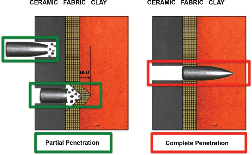
FIGURE 2-1 Partial and complete ballistic penetration. In a partial penetration the projectile stops within the armor structure, whereas in a complete penetration, it exits the armor structure. Note that the clay is not part of the armor structure but is placed behind the armor to record its deformation. BFD, back-face deformation.
This section describes the testing and analysis of complete armor systems. The experimental approaches used to understand the behavior and measure the properties of individual materials are discussed in Chapters 3 through 5.
Measurement of both partial and complete penetration by threats of the separate material composing the system and of the full armor system is key to understanding how materials are selected for use in armor systems to protect against ballistics. In the case of body armor, in addition to the ability of the armor to stop the projectile, there is another requirement—namely, that the deflection of the backside of the armor toward the wearer be small.
The specifics of the tests used to qualify armor systems for field use are well documented and will not be described at length here. As an example, the very elaborate requirements for the testing of body armor are described in great detail in the National Institute of Justice (NIJ) standard.2 In addition, a recent National Research Council (NRC) report examined specific aspects of the techniques used to evaluate body armor.3Yet another recent report by the Department of Defense (DoD) Office of the Inspector General4 described the Army’s testing to certify armor. Although the purchase specification for body armor might seem insensitive, it allows for an “acceptable number of complete and partial penetrations,” as shown in Figure 2-1. An additional parameter for body armor certification is the maximum depth of the back-face deformation for partial penetrations. (Back-face deformation is the depth of the crater left by each partial penetration in the clay placed behind the armor during testing with threats. It represents the blunt force trauma inflicted on the wearer, which can contribute to injury or even death.) The accepted deformation of the back face of an armor system is currently 44 mm (1.73 in.) or less5 (see Figure 2-1).
To assess the different threats against a particular armor system, two key measurements, V0 and V50, are made. V0, the ballistic limit, is “the maximum velocity at which a particular projectile is expected to consistently fail to penetrate armor of given thickness and physical properties at a specified angle of obliquity.”6 If the measured V0 exceeds the maximum velocity for a particular threat (see Table 2-1) the armor system is said to defeat that threat. Essentially, the
______________
2Department of Justice. 2008. Ballistic Resistance of Body Armor, NIJ Standard–0101.06. Available online at http://www.ncjrs.gov/pdffiles1/nij/223054.pdf. Last accessed April 15, 2011.
3NRC. 2009. Phase I Report on Review of the Testing of Body Armor Materials for Use by the U.S. Army: Letter Report. Washington, D.C.: The National Academies Press. Available online at http://www.nap.edu/catalog.php?record_id=12873. Accessed April 7, 2011.
4Inspector General, Department of Defense. 2009. DoD Testing Requirements for Body Armor, Report No. D-2009-047. Available online at http://www.dodig.mil/audit/reports/fy09/09-047.pdf. Last accessed April 15, 2011.
5Department of Justice. 2008. Ballistic Resistance of Body Armor, NIJ Standard–0101.06. Available online at http://www.ncjrs.gov/pdffiles1/nij/223054.pdf. Last accessed April 15, 2011.
6Department of Defense. 1997. Department of Defense Test Method Standard: V50 Ballistic Test for Armor, MIL-STD-662F, December 18. Aberdeen Proving Ground, Md.: U.S. Army Research Laboratory.
TABLE 2-1 National Institute of Justice (NIJ) Ballistic Threat Standards
|
|
||||
| Level | Projectile | Weight (g) | Velocity (m/s) | Kinetic Energy (Relative to Type IIA) |
|
|
||||
| Type IIA | 9 mm full-metal-jacketed round nose (FMJ RN) .40 S&W FMJ | 8.0 11.7 |
373±9.1 352±9.1 |
1.0 1.3 |
| Type II | 9 mm FMJ RN .357 magnum jacketed soft point (JSP) | 8.0 10.2 |
398 ± 9.1 436 ± 9.1 |
1.1 1.7 |
| Type IIIA | .357 SIG FMJ flat nose (FN), .44 magnum semijacketed hollow point (SJHP) | 8.1 15.6 |
448 ± 9.1 436 ± 9.1 |
1.5 2.7 |
| Type III (rifles) | 7.62 mm FMJ, steel-jacketed bullets (U.S. military designation M80) | 9.6 | 847 ± 9.1 | 6.2 |
| Type IV (armor-piercing rifle) | .30 caliber armor-piercing (AP) bullets (U.S. military designation M2 AP) | 10.8 | 878 ± 9.1 | 7.5 |
|
|
||||
qualification tests described above ensure that V0 exceeds the performance specification.
However, the expense of firing and the inability to control projectile velocity exactly makes the determination of 0 percent penetration statistically problematic during the experimental phase of armor development. The determination of V0 is therefore generally reserved for the final stages of development and qualification.
For research and development purposes, the use of V50, “the velocity at which complete penetration and partial penetration are equally likely to occur,” is much more prevalent. These tests are done with a configuration similar to that in Figure 2-1 but without the clay, which is replaced by a “witness plate” placed at a distance behind the armor configuration. A complete penetration event takes place when a thin witness plate is fully penetrated, or perforated, by the projectile; partial (or no) penetration takes place when no perforation of the witness plate is observed. To calculate V50, the highest partial/no penetration velocities and the lowest complete penetration velocities are used, generally with at least 4 and often as many as 10 shots—enough to make sure there are at least two partial/no and at least two complete penetrations.
During the development of armor systems, it is much more important to understand what is actually occurring during the penetration event than it is to simply measure V0 or V50. To this end, ballistic ranges are often equipped with an array of sophisticated diagnostic tools. For example, at Aberdeen Test Center (ATC), projectile velocity is measured with optical screens and electronic counters before, inside, and after passing the target.7 The ATC range also has high-speed cameras that can capture 6,688 frames per second at full resolution and up to 100,000 frames per second at lower resolutions. In addition, flash x-rays can provide a three-dimensional reconstruction of a material’s deformation and failure during a ballistic event. 8 It is clear that researchers wish for additional real-time measurements on ballistic time scales both locally and globally in relation to the point of impact. The ability to make quantitative measurements across many properties would necessitate approaches and methods wholly beyond those that are currently known.
Figure 2-2, taken from an earlier NRC study,9 shows a typical range at ATC as well as one at New Lenox Machine Co.
Exemplary Threats and Armor Designs
Although the testing and definitions described above hold for all classes of armor systems, the threats and the design philosophy are completely dependent on how the armor is used. Thus, each of the three applications focused on in this report (personnel, vehicle, and transparent armors) are treated separately. It should be noted that military armor systems are currently purchased according to performance specifications that are classified. Descriptions of threats and designs in this study are taken from the open literature and documents approved for public release. As such, they are only illustrative of current threats and designs.
Modern armor for personnel protection includes both body armor and combat helmets. The threats for which personnel armor is designed are small-caliber projectiles, including both bullets and fragments. The level of ballistic protection of personnel armor is taken as the total kinetic energy of a single round that the armor can stop.10 The stan-
______________
7Rooney, J.P. 2008. Army Aberdeen Test Center Light Armor Range Complex. ITEA Journal 29: 347-350.
8An example of using flash x-rays to observe the sample and projectile changes during a penetration event is shown in Figure 2-6, which is discussed later in this chapter.
9NRC. 2009. Phase I Report on Review of the Testing of Body Armor Materials for Use by the U.S. Army: Letter Report. Washington, D.C. : The National Academies Press. Available online at http://www.nap.edu/catalog.php?record_id=12873. Accessed April 7, 2011.
10Montgomery, J.S., and E.S. Chin. 2004. Protecting the future force: A new generation of metallic armors leads the way. AMPTIAC Quarterly 8(4): 15-20.
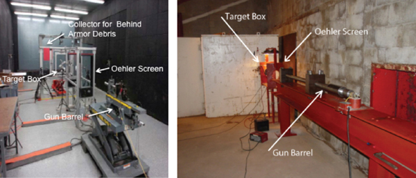
FIGURE 2-2 Indoor firing ranges. Depicted are (left) the gun barrel (foreground) and Oehler screens at the light armor range complex, which measure velocity midway between the barrel and target. The target box contains the target being shot at and debris. The red panel collects behind-armor debris. Depicted at right is an alternative setup for a commercial indoor firing range at New Lenox Machine Co. SOURCE: Adapted from John Wallace, Technical Director, ATC, “Body armor test capabilities,” presentation to the Committee to Review the Testing of Body Armor Materials for Use by the U.S. Army, on March 10, 2010.
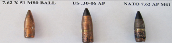
FIGURE 2-3 Examples of 7.62 mm (.30 cal) small arms projectiles. SOURCE: Courtesy of Robert Skaggs.
dards set by the NIJ shown in Table 2-111 are for typical ballistic threats, although not specifically those for military body armor, which are classified. Note that a Type IV projectile has more than 7.5 times the energy of a Type IIA projectile.
In addition to surviving the impact of specific projectiles (see Figure 2-3), there is generally a requirement to withstand multiple hits on the same armor panel. For armor meeting NIJ Type IIA and Type III standards, panels must demonstrate the ability to survive six hits without failure. Only Type IV has no multi-hit requirements.12Personnel protection armor is also often designed against fragments.
Finally, for body armor, as previously mentioned, stopping penetration is not the only issue. It is also important that when stopping the projectile, the armor itself does not deflect to an extent that would severely injure the wearer. This puts an additional constraint on body armor systems. (See the preceding discussion on back-face deflection.)
Design Considerations for Fielded Systems
The design of armor for personnel protection depends on the specific threat. For fragments and lower velocity penetrators, vests are typically made from polymer fibers (see Chapter 5). Advances in fibers for personnel armor began with the use of fiberglass and nylon. These were followed in the late 1960s by polyaramid fibers (DuPont PRD 29 and PRD 49), now called Kevlar. Later, high molecular weight polyethylene fibers, made of Spectrashield and Dyneema, were also used as backing in vests. Zylon, made of polybenzobisoxazole (PBO), has also been considered. Figure 2-4 depicts how the evolution of fibers has steadily improved the performance of polymer vests. Thus, the primary factor in the design of armor for vests is the selection of the fiber.
When the threat increases to rifle rounds, including
______________
11Department of Justice. 2008. Ballistic Resistance of Body Armor, NIJ Standard–0101.06. Available online http://www.ncjrs.gov/pdffiles1/nij/223054.pdf. Last accessed April 15, 2011.
12Ibid.
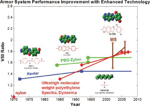
FIGURE 2-4 Increase in ballistic performance as a function of improved fibers. This figure depicts how the V50 of fiber-based vests has increased as new fibers have been introduced over the years. SOURCE: Philip Cunniff, U.S. Army Natick Soldier Research, Development and Engineering Center, “Fiber research for soldier protection,” presentation to the committee, March 10, 2010.
armor-piercing projectiles (see Table 2-1, Types III and IV), ballistic fabric alone is insufficient. Stopping these threats requires adding a ceramic plate to the outside of the vest. The hard ceramic blunts and/or erodes the projectile nose, which increases the projected area of the projectile and spreads the load across more of the fabric.13It is the combination of two independently developed materials—a ceramic faceplate and a fiber fabric—that constitutes the armor system and provides overall protection. The combination creates a complex system where the performance of the ceramic and the polymer backing (vest) are intimately connected. An extended discussion of ceramics and polymer protection materials can be found in Chapter 5.
The currently fielded body armor, the Interceptor body armor (IBA), makes use of the combination of ceramic and fiber described above and shown in Figure 2-5.14 The main component of this armor is the improved outer tactical vest, which provides protection against fragments and 9-mm rounds.15 Enhanced small-arms protective insert (ESAPI) ballistic plates and enhanced side ballistic insert plates are inserted into plate carrier pockets in the polymeric vest. These plates can withstand multiple small-arms hits, including armor-piercing rounds.16
IBA can stop small-arms ballistic threats and fragments, thus reducing the number and severity of wounds. An improvement, the X small-arms protective insert, is designed for “potential emerging small arms ballistic threats.”17
The deltoid and axillary protectors, an integral component of the improved outer tactical vest, extend protection against fragments and 9-mm rounds to the upper arm areas (see Figure 1-1).18
The combination of ceramic inserts and polymeric fibers in the IBA vest is an example of how particular arrangements of specific materials make up a typical armor system. The complexity goes even further: A change in threat can drastically change the performance of a given armor system. Figure 2-6 shows how the Nammo 7.62-mm M993 tungsten carbide projectile, with a velocity of 970 m/sec, more easily defeats a B4C ceramic plate than does the Type IV APM2 threat. This indicates how armor systems solutions are intertwined with the specific threat they are intended to defeat.
Because helmets and vests demand similar levels of pro-
______________
13Montgomery, J.S., and E.S. Chin. 2004. Protecting the future force: A new generation of metallic armors leads the way. AMPTIAC Quarterly 8(4): 15-20.
14Inspector General, Department of Defense. 2009. DoD Testing Requirements for Body Armor. Report No. D-2009-047, January 29. Available online at http://www.dtic.mil/cgi-bin/GetTRDoc?AD=ADA499208&Location=U2&doc=GetTRDoc.pdf. Last accessed April 29, 2011.
15Figure 2-5 shows the version of tactical vest before the improved outer tactical vest was introduced.
16U.S. Army. 2010. Interceptor Body Armor (IBA) brochure, October. Available online at https://peosoldier.army.mil/FactSheets/PMSPIE/SPIE_SPE_IBA.pdf. Last accessed April 29, 2011.
17Ibid.
18Ibid.
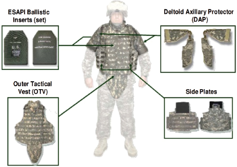
FIGURE 2-5 Interceptor body armor. Shown are the various components that make up the Interceptor body armor system (see DoD Inspector General’s Report No. D-2009-047, January 29, 2009). The outer tactical vest, the deltoid axillary protectors, and the carrier for the ESAPI inserts (not shown) are made of Cordura, Kevlar, and/or Twaron fabric. The ESAPI ballistic inserts are composite ceramic plates with ballistic fiber backing (see the Interceptor body armor [IBA] brochure of the Program Executive Office, Soldier, October 2010). SOURCE: DoD Inspector General. 2009. DoD Testing Requirements for Body Armor. Report No. D-2009-047, January 29. Available online at http://www.dtic.mil/cgi-bin/GetTRDoc?AD=ADA499208&Location=U2&doc=GetTRDoc.pdf. Last accessed April 29, 2011.
tection, primary ballistic protection is also based on the performance of the fiber. However, the currently fielded helmet, the advanced combat helmet (see Box 2-2 for materials of construction), must not only provide ballistic protection, but it must also protect against blunt forces. Equally important, the helmet must provide comfort and thermal management without degrading vision or hearing and be able to interface with other equipment, including night vision goggles and
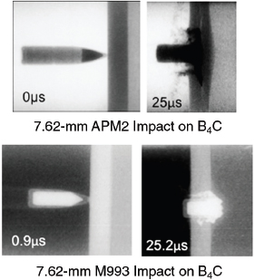
FIGURE 2-6 Effect of a ballistic threat on performance. This figure shows X-ray exposures during two impacts on boron carbide plates, each with a different type of projectile. In the top set, a 7.62-mm Type IV APM2 has not yet fully penetrated the ceramic after 25 microseconds. In the bottom set, in the same time frame, the 7.62-mm M993 projectile has begun to exit the ceramic. This is striking evidence of the effect of different threats on the performance of ballistic armor. SOURCE: Adapted from William Gooch, Jr., U.S. Army Research Laboratory, “Overview of the development of ceramic armor technology—Past, present and the future,” presentation at the 30th International Conference on Advanced Ceramics and Composites, Cocoa Beach, Florida, January 24, 2006.
BOX 2-2
Construction of the Advanced Combat Helmet
Component materials:
- Helmet shell: aramid fabric + resin.
- Chin strap: Cotton/polyester webbing and foam nape pad, or nylon webbing and leather nape pad; foam pads are made of polyurethane.
__________
SOURCE: U.S. Army. 2010. Advanced Combat Helmet (ACH) brochure, October. Available online at https://peosoldier.army.mil/Factsheets/PMSPIE/SPIE_SPE_ACH.pdf. Last accessed April 29, 2011.
weapons.19,20 Ultimately, the weight of the helmet is limited by the ability of the neck to bear weight, especially over long periods of time.
While vehicle armor is generally understood to encompass armor systems to protect all classes of vehicles, this study will focus on armor protection for land vehicles such as the M1A1/M1A2 Abrams main battle tank, the Bradley fighting vehicle, the Stryker combat vehicle, and the high-mobility multipurpose wheeled vehicle (HMMWV, or Humvee) (see Figure 2-7).
Like personnel armor, vehicle armor is also typically required to protect against small-caliber projectiles and fragments. In addition, however, it is required to stop a host of other threats. These include medium- and large-caliber ballistic threats (20-140 mm);21 shaped charge munitions, as depicted in Box 2-3; and chemical energy munitions. Rocket-propelled grenades are ubiquitous in the world of terrorists owing to the efforts of the countries that manufacture them to market them to developing countries. Because little effort was made to destroy ammunition dumps during the invasion of Iraq, the artillery projectiles left behind have since been used to fashion improvised explosive devices. Countries such as Iran have taken it upon themselves to manufacture many sizes of projectiles that are nominally concave metal disks propelled by large cylindrical high-explosive charges.
Specific requirements for the multithreat environment to which truck and tactical wheel systems are exposed are defined by the Army’s long-term armor strategy specifications, which are classified.
Design Considerations for Fielded Systems
The design of armor systems for vehicles depends on the size of the vehicle, the threat or threats the vehicle is likely to encounter, and, equally important, the weight of the armor that the vehicle can handle. Since the early days of tanks in World War I, metal has been the primary armor material used for large combat vehicles. Table 2-2 gives selected examples of such materials and their applications.
Figure 2-8 depicts the various classes of armor that are in use or under consideration for combat vehicles. This study considers only the passive armor systems; electromagnetic, energetic, and smart armor are beyond its scope, as are reactive armor systems.
As with personnel protection, passive vehicle protection is generally a complicated arrangement of material layers, each serving a different role in the overall protection schedule. Figure 2-9 schematically depicts one such arrangement that comprises six layers of various materials, including ceramics, metals, and polymers.22 Note that the entire system serves many more functions than just protection against projectiles.
Unlike designs for protecting personnel, armor designs for vehicles are less constrained in thickness. This allows for a concept known as “spaced armor,” another option for the arrangement of armor. In spaced armor, a thin armor plate is separated from the main armor system with the goal of breaking up or disrupting the projectile, thus making it easier for the remainder of the armor to stop it. This concept was used by the Germans in World War II23 and in various armor configurations since. It should also be noted that, even if the threat does not completely exit the armor, pieces of the back face can be accelerated by the shock wave, creating spall, which can have sufficient velocity to considerably damage people and equipment inside the vehicle. Thus, armor design must minimize behind-the-armor damage, which can ad-
______________
19U.S. Army. 2010. Advanced Combat Helmet (ACH) brochure, October. Available online at https://peosoldier.army.mil/Factsheets/PMSPIE/SPIE_SPE_ACH.pdf. Last accessed April 29, 2011.
20Walsh, S.M., B.R. Scott, T.L. Jones, K. Cho, and J. Wolbert. 2008. A materials approach in the development of multi-threat warfighter head protection, December. Available online at http://www.dtic.mil/cgi-bin/GetTRDoc?AD=ADA504397&Location=U2&doc=GetTRDoc.pdf. Last accessed April 29, 2011.
21Normandia, M.J., J.C. LaSalvia, W.A. Gooch Jr., J.W. McCauley, and A.M. Rajendran. 2004. Protecting the future force: Ceramics research leads to improved armor performance. AMPTIAC Quarterly 8(4): 21-27.
22William Gooch, Jr., U.S. Army Research Laboratory, “Overview of the development of ceramic armor technology—Past, present and the future,” presentation at the 30th International Conference on Advanced Ceramics and Composites, Cocoa Beach, Fla., January 24, 2006.
23A. Hurlich. 1950. Spaced Armor. Available online at http://www.dtic.mil/cgi-bin/GetTRDoc?AD=ADA954865&Location=U2&doc=GetTRDoc.pdf. Last accessed April 29, 2011.
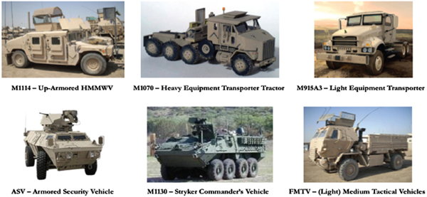
FIGURE 2-7 Examples of Army combat vehicles. This figure portrays a subset of combat vehicles for which ballistic and/or blast protection is a critical consideration. SOURCE: Photo courtesy of the U.S. Army.
BOX 2-3
Shaped Charge Characteristics
Shaped charges are made by inverting a soft metal cone (typically copper) that will be propelled by an explosive charge to velocities near 10,000 m/s. The copper slug is hydrodynamically driven into the plastic regime and stretches continuously as it is propelled forward toward the target. At some point it starts to separate into a string of liquidlike particles, but before this occurs it is just like a long rod penetrator that is traveling at supersonic speed and will penetrate great thicknesses. The optimum standoff distance for a chemical energy penetrator is between 2.4 and 4 cone diameters. At this distance, the penetrator will not have started to fragment before it hits the target. The example below shows (1) copper liner, (2) charge, (3) body, (4) booster, and (5) initiation charge.
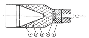
TABLE 2-2 Metallic Armor Materials
| Metal | Military Specification | Application |
| Rolled homogeneous armor | MIL-DTL-12560 | M1A1/M1A2 Abrams light armored vehicle, above beltline |
| High-hardness steel armor | MIL-DTL-46100 | M1A1/M1A2 Abrams light armored vehicle, below beltline |
| Aluminum alloy 5083-H131 | MIL-DTL-46027 | M113 armored personnel carrier M109 Paladin self-propelled howitzer Bradley fighting vehicle, lower half |
| Aluminum alloy 7039-T64 | MIL-DTL-46063 | Bradley fighting vehicle, upper half |
SOURCE: Montgomery, J.S., and E.S. Chin. 2004. Protecting the future force: A new generation of metallic armors leads the way. AMPTIAC Quarterly 8(4): 15-20.
versely affect the survival of the crew even if the projectile is stopped.24
Before the start of the current conflicts, light vehicles (e.g., Humvees and light trucks) were lightly armored if at all. However, unanticipated threats began to be seen—for example, rocket-propelled grenades and improvised explosive devices—causing a rethinking of that approach. Programs to quickly up-armor the Humvees and other vehicles were
______________
24Prakash, A. 2004. Virtual Experiments to Determine Behind-Armor Debris for Survivability Analysis, December. Available online at http://www.dtic.mil/cgi-bin/GetTRDoc?AD=ADA433014&Location=U2&doc=GetTRDoc.pdf. Last accessed April 29, 2011.
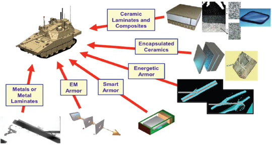
FIGURE 2-8 Examples of vehicle protection. This figure shows the many types of protection systems that are used or under consideration for Army combat vehicles. This study looks at only those materials that passively protect the vehicle from ballistics and blast threats. SOURCE: Christopher Hoppel, Chief, High Rate Mechanics and Failure Branch, Army Research Laboratory, “Multi-scale modeling of armor materials,” presentation to the committee, March 10, 2010.
established. Since August 2004, all Marine Corps vehicles operating outside the forward operating bases have had their armor protection upgraded.25 Consequently, there is now a very large array of armor combinations, often with one kit laid on top of the other, making the scheme shown in Figure 2-9 simple by comparison.
Since a bomb blast severely damaged the U.S.S. Cole on October 12, 2000, taking 19 lives, the Navy has also shown more interest in developing structures that can survive a blast. A Navy multidisciplinary research program known as Integrated Cellular Materials Approach to Force Protection is developing complex, topologically designed sandwich panels for this application. Like vehicle armor, these panels must protect against both ballistic and other threats.
The windshields and side windows of vehicles such as Humvees and trucks are an important application for transparent armor. Currently, such windows are designed to protect against armor-piercing threats as well as high-velocity fragments. In addition, they must be able to withstand multiple hits and to fracture in a way that maintains their structural integrity and transparency. Advanced applications of transparent armor often demand additional protection against electromagnetic fields or lasers. This study, however, will cover only the ballistic requirements of transparent armor.
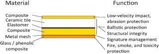
FIGURE 2-9 Schematic of vehicle armor protection system. The armor is made of many layers, each with a different overall function. In this construct, ballistic protection is obtained primarily through the ceramic tile and composite backing. The composite faceplate also contributes to the protective properties of the vehicle armor, while the ballistic components contribute to the structural integrity of the armor. Other configurations (not shown) might include a structure designed primarily for blast resistance. SOURCE: William Gooch, Jr., U.S. Army Research Laboratory, “Overview of the development of ceramic armor technology—Past, present and the future,” presentation at the 30th International Conference on Advanced Ceramics and Composites, Cocoa Beach, Fla., January 24, 2006.
The specifications for transparent armor are called out in Army Tank Purchase Description (ATPD) 2352P, July 7, 2008,26 which describes the general characteristics that transparent armor must possess to qualify for purchase. These
______________
25Gen. William L. Nyland, Assistant Commandant of the Marine Corps, and Major General (Select) William D. Catto, Commanding General Marine Corps Systems Command, Statement before the House Armed Services Committee on Marine Corps vehicle armoring and improvised explosive device countermeasures, June 21, 2005.
26ATPD 2352P, July 7, 2008, supersedes ATPD 2352N, January 3, 2008. ATPD 2352 defines a standardized four-shot pattern and is used throughout the Army to provide consistent criteria for evaluating multiple impacts on transparent armor. ATPD 2352P is available at https://aais.ria.army.mil/AAIS/award_web_09/W52H0909A00030000/Award_attach/Attach1.pdf.
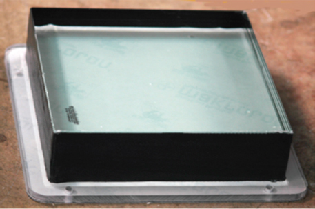
FIGURE 2-10 Example of transparent armor for a vehicle window. SOURCE: Stephan Bless, Institute for Advanced Technology, University of Texas at Austin, “Transparent armor research issues,” presentation to the committee, March 10, 2010.
specs also set forth criteria for the environmental effects of transparent armor. As with other documents on applications of armor, DTA184044, the document that describes the threats that must be defeated, is contained in a classified appendix and so cannot be elaborated on here.
Design Considerations for Fielded Systems
In contrast to conventional opaque ceramic armors, the design of transparent armor is often driven by the multi-hit requirement, a requirement mostly achieved by layering (see Figures 2-10 and 5-14). A typical transparent armor uses a layer of glass or glass ceramic followed by a layer of polycarbonate and then other similar layers until seven or more have been stacked and bonded with polyvinyl butyral adhesive layers. While the backing of transparent armor is primarily polycarbonate, other polymeric materials, such as polyurethane, are showing some potential.
Most current armor windows are laminates of glass and plastic.27 The three main transparent ceramic candidates are currently aluminum oxynitride (AlON), magnesium aluminate spinel (MgAl2O4), commonly referred to as spinel, and single-crystal aluminum oxide (Al2O3-sapphire).28 These materials are described further in Chapter 5.
FROM ARMOR SYSTEMS TO PROTECTION MATERIALS
The goal of armor system development is (1) to continually decrease the weight—that is, to increase Em—required to protect against a given threat or (2) to not increase the weight required to protect against a greater threat. According to the Army, new armor systems can in fact be delivered to the field relatively quickly. However, this is generally because new armor configurations and materials are not radically different from those that have already been demonstrated to be effective. This is best illustrated by looking at how one presently designs an armor system in response to a new threat.
While there is no unique way to design an armor system, Figure 2-11 reflects what the study committee heard from several presenters representing the Army Research Laboratory and from other invited speakers. Figure 2-11 also demonstrates several major limitations that impact protection materials research. These will be addressed in subsequent chapters.
In response to a new threat against which current armor systems fail, a new armor system concept—including geometry, configuration, and materials—is chosen that, from experience, designers hope will defeat the new threat. Changes in geometry can be as simple as adding thicknesses to various layers in an existing configuration; possible, but less likely, is an entirely new design. Materials are chosen from a set of available materials whose ballistic and blast performance have already been proven both as individual
______________
27Patel, P.J., G.A. Gilde, P.G. Dehmer, and J.W. McCauley. 2000. Transparent armor. The AMPTIAC Newsletter 4(3): 1, 2-5, 13.
28Sands, J.M., P.J. Patel, P.G. Dehmer, A.J. Hsieh, and M.C. Boyce. 2004. Protecting the force: Transparent materials safeguard the Army’s vision. AMPTIAC Quarterly 8(4):28-36.
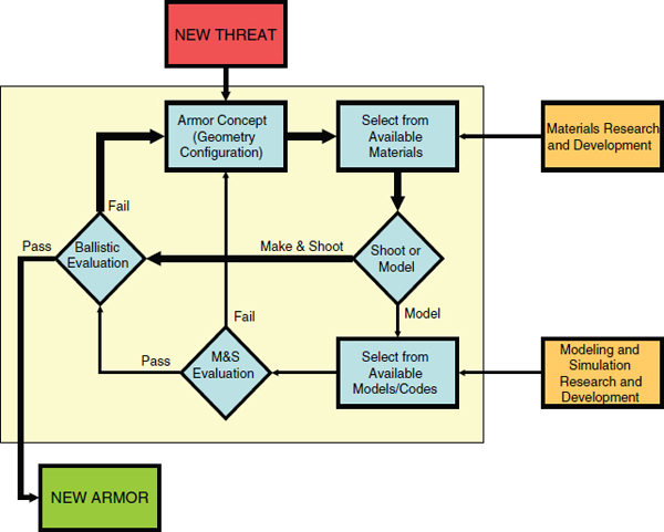
FIGURE 2-11 Current paradigm for armor design. In response to a new threat, a new concept and materials are chosen and then tested or modeled depending on several factors. Armor that fails ballistic testing is redesigned and the (costly) process begins again. The goal is to reduce repetitive looping by making better use of modeling and simulation. It should be noted that, while computations are sometimes used, the shoot-and-look mode is much more common. In addition, the materials research and development community and the modeling and simulation community are not particularly well connected.
materials and combined with other materials. While much excellent materials research is under way, emerging research materials are seldom, if ever, chosen for new armor because there is no way to directly tie how they perform in a research environment to how they will perform in the actual armor configuration. Moreover, most nonarmor applications materials are chosen according to their bulk quasi-static properties, such as hardness, strength, and toughness, even though such properties do not always predict the materials’ ballistic or blast performance. This issue will be discussed extensively in Chapter 3.
The next step is deciding how to evaluate the candidate armor system. Although it might seem intuitive to run simulations before expensive testing, the decision on how to test the new configuration actually depends on several factors. If the armor varies only slightly from existing armor, then the most expedient method might well be to build the armor and go straight to a ballistic evaluation. However, if the armor design is significantly different from current armor systems, there are limitations to the effectiveness of modeling and simulation. If the properties of the materials—that is, the constitutive relations needed to run computational material models for them—are not known, then the modeling would have to use information from the most similar existing material, making the result uncertain. This is another reason why armor designers do not consider using research materials that have not yet been sufficiently characterized under appropriate dynamic conditions (see Chapter 4). Consequently, modeling and simulation are often used more as a guide to identify trends due to design changes than as a source of absolute results. Thus, even configurations that survive the modeling and simulation step may fail ballistic testing. Chapter 4 elaborates on the limitations of how well the material can be modeled and addresses shortcomings in the models themselves.
Armor that fails ballistic testing is redesigned and the process begins again. Once there is a successful ballistic test, the armor will be constructed in sufficient quantities
to qualify the new configuration for fielding. It can only be hoped that a new armor design comes about without too many loops (as shown in the Figure 2-11 diagram), which are costly in terms of effort. More important, repetitive looping delays the fielding of new armors, which in turn adversely impacts the safety of troops. At the same time, speed must be offset by the need to make sure the armor will perform as expected in the field.
As described, the current armor design paradigm clearly makes it difficult to incorporate a new material into existing armor systems or to use it in an entirely new design. Any path forward for future generations of lightweight armor materials must alter this paradigm, although it will not be an easy undertaking. As has been shown in this chapter, the ultimate performance of an armor system depends on the materials used and on the geometric arrangement of those materials, both of which vary according to threat and the application. The challenge is to represent the complications inherent in materials in a way that allows designers to focus on the materials independently of the specific armor system design or threat that the armor is intended to thwart. As will be shown in Chapter 3, meeting this challenge will require an understanding of how to relate the behavior of a material—especially its failure behavior—during ballistic or blast events to its initial structure and composition. Chapter 4 describes approaches for successfully predicting the theoretical and experimental failure behavior of a protection material for the benefit of the materials research community. Finally, it will be important to convey information about armor performance to those developing armor materials.
It is important to acknowledge the security restrictions that surround protection materials. Such limitations are prudent and necessary but require periodic review to ensure they are consistent with the current state of open knowledge and do not unnecessarily restrict the exchange of information with an open research community when such an exchange would be beneficial to national security.
The information content of this study, which deals with armor systems and armor performance, is bound by both security regulations and export control law. The security limitations generally imposed by the Army in this area restrict the discussion of performance of certain armor system designs against specific threats. These limitations extend to the ability to test armor systems with militarily relevant threats. The details of specific threats and design are generally not published in the open literature. Even the availability of information on armor systems that is not proprietary or classified is often restricted by DoD to DoD and contractors to DoD. The underlying technical basis for these restrictions may be available to researchers working on armor under contract to DoD, but it is not generally available to researchers outside of that context.
In addition, there are export control restrictions that generally limit the distribution of information to U.S. citizens and lawful permanent residents. The restrictions that apply to armor materials cover almost all of the relevant protection materials, including ceramics near theoretical density—among them B4C (boron carbide), SiC (silicon carbide), and Al2O3 (aluminum oxide, or alumina), discussed in Chapter 5—composite materials, arrays of woven cloth, metals, and ceramics, and layers of metals.
Information in the public domain as defined in 22 CFR 120.11 is generally not subject to International Traffic in Arms Regulations (ITAR). The definition of “technical data” that is subject to the export control regulations does not include “information concerning general scientific, mathematical or engineering principles commonly taught in colleges and universities or information in the public domain.”29
The combination of security regulations and ITAR makes it extremely difficult for fundamental research in protection materials to connect to the development of restricted armor systems. Ultimately much of work on armor is restricted. For example, a quick search of the Defense Technical Information Center database for “vehicle armor” indicates that only about 30 percent of the technical documents from 2005 through 2010 are approved for public release. Clear, up-to-date boundaries need to be specified between restricted and unrestricted information and related research. Such a review, however, is beyond the scope of this report.
This report is a public document, and its content is limited to general descriptions of threats, performance, and design that may be discussed without restriction. While the restrictions discussed above suffice for the needs of this study, it is important to note that they can significantly complicate the use of available information in basic research.
__________
2922 CFR 120.10(a)(5).


