
Appendix J
Fiber-Reinforced Polymer Matrix Composites
Polymer matrix composites (PMCs) consist of a polymer resin reinforced with fibers, an example of which is the combat helmet. PMCs can be subdivided into two categories, based on whether the fiber reinforcement is continuous or discontinuous. PMCs with discontinuous fibers (less than 100 mm long) are made with thermoplastic or thermosetting resins, whereas PMCs with continuous fibers usually employ thermosetting resins. This appendix primarily addresses PMCs containing continuous fibers. The most common design for PMCs is a laminate structure made of woven fabrics held together by a polymer resin. Fabrics are incorporated in order to take advantage of their high strength and stiffness and to improve energy absorption and distribute the kinetic energy laterally. Owing to their highly engineered structures, PMCs are lightweight with high specific strength and high specific stiffness.
Commonly used reinforcement materials include carbon, glass, aramid, and polyethylene fibers. PMCs can be manufactured by wet and hand lay-up; molding (compression, injection, and transfer); vacuum bag molding; infusion molding; vacuum-assisted resin transfer molding; prepreg1 molding; and other common fabrication techniques. Unlike common structural composites, which typically contain up to about 60 vol percent fibers, ballistic PMCs contain a higher volume fraction of fibers or fabrics (up to about 80 vol percent). The effect of this variation in structure on the ballistic protection properties of PMCs has not been thoroughly investigated.
PMCs respond to ballistic impact in ways that depend on their particular structure and thus are different from other protective materials. Unlike fabrics, with PMCs only the material in the neighborhood of the impact position shows a response; thus the response is completely governed by the local behavior of the material and unaffected by boundary conditions. Additionally, the penetration mechanism is dependent on the thickness of the composite. For thin composites the deformation across the thickness direction does not vary with depth, whereas for thick composites it does.2 Ballistic performance initially increases linearly with the increased thickness; however, as the composite becomes thicker the marginal protective gain incurred by increasing the thickness becomes smaller,3,4although the rate at which the weight increases is maintained.
DEFORMATION AND FAILURE MECHANISMS
When a PMC is subjected to high-velocity impact, the kinetic energy is transferred from the projectile to the PMC. The existence of two components, the fabric and the matrix, and their interface, makes the energy absorption mechanism more complex than that of ballistic fabrics. The commonly recognized energy absorption and failure mechanisms are discussed here.
Cone Formation on the Back Face
As with ballistic fabrics, the mode of impact response known as cone formation has also been observed in PMCs. Guoqi et al.5 observed the formation of a cone-shaped σf (ε, ἑ,T) deformation zone in the back surface of Kevlar/polyester laminates during the ballistic impact of a blunt projectile; using high speed photography, Morye et al.6 documented the temporal evolution of this response for the ballistic behavior of nylon fabric preimpregnated with
______________
1Semifinished fiber products preimpregnated with epoxy resin (prepregs).
2Naik, N., and A. Doshi. 2008. Ballistic impact behaviour of thick composites: Parametric studies. Composite Structures 82(3): 447-464.
3Ibid.
4Faur-Csukat, G. 2006. A study on the ballistic performance of composites. Macromolecular Symposia 239 (1): 217-226.
5Guoqi, Z., W. Goldsmith, and C.K.H. Dharan. 1992. Penetration of laminated Kevlar by projectiles—I. Experimental investigation. International Journal of Solids and Structures 29(4): 399-420.
6Morye, S., P. Hine, R. Duckett, D. Carr, and I. Ward. 2000. Modelling of the energy absorption by polymer composites upon ballistic impact. Composites Science and Technology 60(14): 2631-2642.
a matrix of a 50:50 mixture of phenol formaldehyde resin and polyvinyl butyral resin. Figure J-1 shows the scheme of cone formation in two-dimensional woven fabric composites during projectile impact. The yarns that the bullet directly contacts are called primary yarns; these yarns resist penetration and undergo deformation due to cone formation. The longitudinal compressive stress wave generated upon impact propagates outward along the yarn direction, forming a quasi-circular shape. The conical portion moves backward and stores kinetic energy by its motion.
Deformation of Yarns and Failure
When a PMC undergoes ballistic impact, the primary yarns deform and resist projectile penetration. The other yarns (called orthogonal yarns) also deform, but to a lesser extent due to primary yarn deformation; this process stores kinetic energy. During cone formation, strain is highest along the middle primary yarns in each layer of the composite. The highest overall strain is at the point of impact, and the strain falls off along the radial direction. After the cone forms, the top layers of the PMC are compressed, leading to an increase in the tensile strain of the yarns there. A linear relation between strain and depth along the thickness direction can be assumed; see Figure J-1. Once the strain is beyond the failure strain, sequential breakage will occur beginning at the top layer. This yarn failure absorbs additional kinetic energy.
Delamination and Matrix Cracks
During ballistic impact, transverse and longitudinal waves are formed. The geometry of the deformation influences the terminology used to describe the deformation:The waves that move out in the lateral direction (having both longitudinal and transverse polarization) from the point of impact are called transverse, and the waves propagating along the direction of the incident projectile are called longitudinal. A cone of deformation, quasi-lemniscate in shape, is formed due to transverse waves.7 As the longitudinal waves propagate along the yarns, attenuation occurs, leading to strain variations radially from the impact site in the target. The matrix has mechanical properties different from those of the yarns, but it must carry the same deformation lest delamination or slippage occur due to weak adhesion between the yarn and the matrix; there may be damage if the yarn strain is higher than the strain at failure in the matrix. As the material deforms, cracking and delamination will continue until total perforation occurs.8 Research has shown9 that initiation and propagation of delamination occur more frequently along the warp and fill directions than along other directions. Compared to conventional materials, composite materials contain numerous interfaces between the matrix and the fibers, providing multiple locations for cracking to occur. Energy absorption occurs through a combination of cracking, delamination, and shear banding (the latter is dependent on the plasticity of the matrix and possibly of the fibers). Typical shapes of delaminated regions after impact are shown in Figure J-2;10 the noncircular shape is attributed to the anisotropic nature of these materials (different paths of the stress waves, hence different distances that the stress information must travel).
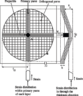
FIGURE J-1 Cone formation during ballistic impact on the back face of the composite target. SOURCE: Naik, N.K. 2005. Ballistic impact behaviour of woven fabric composites:Parametric studies. Materials, Science and Engineering: A 412(1-2): 104-116.
Shear Plugs
During impact experiments on conventional carbon-fiber-reinforced plastic laminates, it was observed11 that a small area of the laminate was sheared off by the projectile
______________
7Wu, E., and L.-C. Chang. 1995. Woven glass/epoxy laminates subject to projectile impact. International Journal of Impact Engineering 16(4): 607-619.
8Naik, N., and K. Reddy. 2002. Delaminated woven fabric composite plates under transverse quasi-static loading: experimental studies. Journal of Reinforced Plastics and Composites 21(10): 869-877.
9Wu, E., and L.-C. Chang. 1995. Woven glass/epoxy laminates subject to projectile impact. International Journal of Impact Engineering 16(4): 607-619.
10Naik, N. 2006. Ballistic impact behaviour of woven fabric composites: Formulation. International Journal of Impact Engineering 32(9): 1521-1552.
11Cantwell, W., and J. Morton. 1990. Impact perforation of carbon fibre reinforced plastic. Composites Science and Technology 38(2): 119-141.
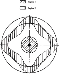
FIGURE J-2 Schematic shape of delaminated regions observed in impact experiments. Region 1: area damage in the first time interval after impact; Region 2: area damaged in the (i + 1) time interval. SOURCE: Naik, N. 2006. Ballistic impact behaviour of woven fabric composites: Formulation. International Journal of Impact Engineering 32(9): 1521-1552.
during impact and that a distinct conical-shaped zone was formed. The schematic is shown in Figure J-3. The shear plug phenomenon has never been observed in glass-fiber-reinforced composites, which may be due to the much higher failure strain of glass fibers compared to that of carbon fibers at high strain rates.
Friction and Hole Enlargement
In contrast to the complex frictional forces present in neat fabrics (including friction between yarns, between the projectile and the yarn, and between the individual fibers), the only friction present in PMCs during impact occurs between the projectile and the laminate. After the yarns and the fabrics fail, friction between the damaged laminates dissipates some of the kinetic energy from the projectile. Goldsmith et al.12 calculated the frictional work by using the friction efficiency between projectile and laminate measured by the quasi-static method. They found that the friction resistance depends on the shape of the projectile and that it increases with increasing composite thickness. Additionally, they calculated the energy dissipated when the projectile enlarges the hole and found that this process also contributes to energy dissipation. Although the energy absorbed due to friction is much larger than that due to hole enlargement, neither of these modes is the major energy absorption mechanism.
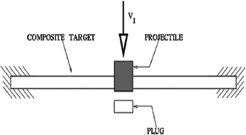
FIGURE J-3 Schematic showing plug formation. SOURCE: Naik, N. 2004. Composite structures under ballistic impact. Composite Structures 66(1-4): 579-590
The Contribution of Different Types of Energy Absorption Paths
Naik and Shrirao13 analyzed the ballistic impact behavior of woven fabric composites under a flat head projectile using wave theory and presented an analytical formulation for each energy absorption mechanism. The calculation is based on the material properties at high strain rate, and analytical prediction shows a good match with experimental results. During the ballistic impact, the moving area of the cone increases, leading to an increase in the kinetic energy of the cone even though the speed of the projectile is reduced. Next, as the moving speed decreases significantly, the kinetic energy of the cone decreases and becomes zero when the projectile’s speed reaches zero. The kinetic energy of the cone is the major energy absorption factor, followed by deformation of the orthogonal yarns and tensile breakage of primary yarns; delamination and cracking provide only a small fraction of the energy absorption. The calculations assume a relatively thin and flexible PMC system; for thicker systems, the variation of deformation as a function of thickness changes the relevant material behavior and requires a consideration of friction.
CURRENT ISSUES AND RELATED STUDIES
As noted above, the ballistic performance of laminated PMCs depends on the properties of the polymer matrix and of the reinforcement material, on the stacking sequence, on the fiber architecture, on the qualities of the interface and the interphase, on the environmental conditions, and on the characteristics of the projectile. To date, however, the experimental studies have only focused on certain types
______________
12Goldsmith, W., C.K.H. Dharan, and H. Chang. 1995. Quasi-static and ballistic perforation of carbon fiber laminates. International Journal of Solids and Structures 32(1):89-103.
13Naik, N., and P. Shrirao. 2004. Composite structures under ballistic impact. Composite Structures 66(1-4): 579-590.
of composites and ballistic conditions. Thus, the full map of ballistic performance of this class of composites is still unknown, and more analytical experiments and simulations are needed to improve the understanding of the ballistic performance of PMCs.
Material Properties
The properties of the fabrics, the surrounding matrix, and the interfaces affect the overall performance of laminates. Although no thorough map of the effects of the properties of fabrics and polymer matrix has been drawn, an examination of the experimental literature allows for some preliminary conclusions. Faur-Csukat14 prepared fabric composites with a fabric wt percent of approximately 55 by hand lay-up followed by compression molding. The ballistic performance of carbon-, glass-, aramid-, and polyethylene-fabric-reinforced composites showed that the efficacy of reinforcing fibers was as follows: Glass is better than aramid, which is better than or equal to ultrahigh-molecular-weight polyethylene (UHMWPE), which is better than carbon fibers. Among the different PMCs studied, carbon-fiber-reinforced composites exhibited the worst ballistic performance owing to their low strain to failure. Roughly, fibers with high strain at high strain rate are better energy absorbers than high-strength fibers with low strain to failure. This conclusion is the same as that of Naik.15The fiber-matrix interface and interphase also play a critical role in ballistic performance. It was observed that weaker interfacial interaction resulted in higher energy absorption.16,17 In composites, fiber-matrix debonding, cracks, and friction slippage improve energy absorption; this is different from the behavior of noncomposite materials. However, excessively low interaction and interfacial strength will lead to pre-ballistic failure problems. For a full understanding of the effects of material properties, more analytical experiments as well as further modeling and simulation are needed.
Fabric Structure
Weave architecture also influences the ballistic performance of composites. It was shown that (under the conditions investigated), the performance of basket-weave fabrics was better by about 10 percent than that of plain-weave fabrics.18 Satin and twill weaves also tended to absorb more energy than the plain weaves,19 possibly due to a decrease in the crimp angle. It was also found that the architecture of the fabric is more important in thicker composites than in thinner composites, as the decreased crimp angle decreases stress concentration.
Improved ballistic performance can be obtained by using three-dimensional woven fabrics instead of two-dimensional woven fabrics.20 Walter et al.21 quantitatively analyzed results from three-dimensional woven glass-fiber-reinforced composites and observed that delamination along the weak layer is the most severe shortcoming in current three-dimensional woven composites at high load and high loading rates. In general, Z-stitching increased the resistance to damage, and it restricted damage to a smaller total area than that in unstitched samples. However, in one study22 a decrease in ballistic limit was observed in Z-stitched targets, although no explanation of this decrease was provided.
Cohen et al.23 used Spectra 1000 yarns to reinforce a UHMWPE matrix with a fiber content of up to 85 percent. The shear strength (20-25 MPa) and tensile strength (longitudinal, 1.3-1.5 GPa; transversal, 21-25 MPa) of the prepared composite are better than those of composites like UHMWPE fiber/epoxy matrix composites and UHMWPE fiber/high-density polyethylene (PE) matrix composites. Furthermore, the tensile strength of the prepared composite is similar to that of Kevlar fiber/epoxy matrix composites. These improvements are attributed to the good self-adhesion and strong bonding of PE fibers to the PE matrix. The ballistic response of PE/PE composites under the impact of bullets (9 mm in diameter, weighing 8 g, velocity approximately 400 m/s) shot from an Uzi submachine gun has been investigated.24 High-density PE was used as the matrix, and UHMWPE fibers such as Spectra and Dyneema were used as the
______________
14Faur-Csukat, G. 2006. A study on the ballistic performance of composites. Macromolecular Symposia 239 (1): 217-226.
15Naik, N. 2004. Composite structures under ballistic impact. Composite Structures 66(1-4): 579-590.
16Park, R., and J. Jang. 1998. A study of the impact properties of composites consisting of surface-modified glass fibers in vinyl ester resin. Composites Science and Technology 58(6): 979-985.
17Tanoglu, M., S. McKnight, G. Palmese, and J. Gillespie Jr. 2001. The effects of glass-fiber sizings on the strength and energy absorption of the fiber/matrix interphase under high loading rates. Composites Science and Technology 61(2): 205-220.
18Faur-Csukat, G. 2006. A study on the ballistic performance of composites. Macromolecular Symposia 239 (1): 217-226.
19Hosur, M., U. Vaidya, C. Ulven, and S. Jeelani. 2004. Performance of stitched/unstitched woven carbon/epoxy composites under high velocity impact loading. Composite Structures 64(3-4), 455-466.
20Shukla, A., J. Grogan, S. Tekalur, A. Bogdanovich, and R. Coffelt. 2005. Ballistic resistance of 2D & 3D woven sandwich composites. Pp. 625-634 in Sandwich Structures 7: Advancing with Sandwich Structures and Materials: Proceedings of the 7th International Conference on Sandwich Structures, O. Thomsen, E. Bozhevolnaya, and A. Lyckegaard, eds. New York, N.Y.: Springer.
21Walter, T., G. Subhash, B. Sankar, and C. Yen. 2009. Damage modes in 3D glass fiber epoxy woven composites under high rate of impact loading. Composites Part B: Engineering 40(6): 584-589.
22Hosur, M., U. Vaidya, C. Ulven, and S. Jeelani. 2004. Performance of stitched/unstitched woven carbon/epoxy composites under high velocity impact loading. Composite Structures 64(3-4), 455-466.
23Cohen, Y., D. Rein, and L. Vaykhansky. 1997. A novel composite based on ultra-high-molecular-weight polyethylene. Composites Science and Technology 57(8): 1149-1154.
24Harel, H., G. Marom, and S. Kenig. 2002. Delamination controlled ballistic resistance of polyethylene/polyethylene composite materials. Applied Composite Materials 9 (1):33-42.
reinforcement phase. The material was created by winding fibers in a unidirectional pattern on large-diameter mandrels which were then flattened into film; these films were stacked on top of one another, with each layer rotated 90° from the one below it to achieve a 0°/90° laminate.
PERSPECTIVE: NEW TYPES OF FIBERS
Nanocomposites
When incorporated into composite materials,25 nano-sized fillers have been shown to provide superior reinforcement due to their outstanding mechanical properties.26Thus, the ballistic resistance dynamics and capacity of carbon nanotubes (CNTs) were simulated, and their potential use in armor was discussed.27 Simulations found that CNTs with the highest ballistic resistance could be resilient to a projectile at speeds of 200 m/s to 1,400 m/s if one end is fixed.28 Additionally, CNT hybrid composites and CNT-reinforced fibers all have potential for improving ballistic performance.
Polymer Laminates
In matrix composites, the reinforcing fibers have mechanical properties that are much higher than those of the matrix. Because this mismatch can cause delamination and cracking, which do not absorb as much kinetic energy as other modes of failure, or for other reasons relevant to the intended use of the product, polymer laminates that contain two or more kinds of polymer have also been investigated. For example, polycarbonate (PC) is widely used in transparent ballistic applications, but its susceptibility to chemicals, scratching, and other possible service conditions limit applications. Two possible solutions have been investigated: (1) blending a second polymer with PC and (2) applying a hard surface coating to the PC. Blending another transparent, chemically resistant polymer such as polymethyl methacrylate (PMMA) with PC can improve the chemical sensitivity, but it can also reduce ballistic performance. Similarly, a hard coating may provide abrasion and chemical protection, but it also reduces impact resistance.29 PC and PMMA are not normally miscible, so blending can only be achieved by solvent casting, which may trap a nonequilibrium structure during solvent evaporation as the solution goes through its glass transition concentration.30 Thus, further phase separation can occur when the temperature is higher than the glass transition temperatures (PMMA Tg = 100°C; PC Tg = 150°C, depending on the component polymer molecular weights). This further phase separation results in strong optical scattering from the larger domains and loss of transparency. Component immiscibility causes opaque materials for melt processing of PMMA and PC blends. Additionally, solvent-induced crystallization of PC decreases optical clarity. Another strategy for addressing the transparency problem is to produce multinanolayer polymer laminates by co-extrusion of PMMA and PC; this results in laminates containing individual layers as thin as 100 nm and an overall structure that has good optical clarity. This method was originally developed at Dow Chemical Company in the 1960s and further refined at the 3M Company and at Case Western Reserve University.31 A system with two extruders and a co-extrusion block is used to extrude two layers that are first sliced vertically, then spread horizontally, and finally recombined. This step can be repeated n times and generate 2(n+1) polymer layers while the thickness of the layers is decreased in proportion to their increased number. The thickness of the PMMA layers plays a critical role in the ballistic performance of PC/PMMA polymer laminates.32 The adhesion between PMMA and PC is strong enough to overcome delamination.33 In this case, the mode of failure depends strongly on the thickness of the individual component layers. For laminates containing the thickest layers (greater than 0.5 m thick), the composite film is brittle, and the laminate fails in brittle mode. For intermediate layer thicknesses (between 150 nm and 0.5 m), several different failure mechanisms are present, with microcracking in the PMMA layers appearing to be the dominant one. Materials with layer thicknesses less than 150 nm behave in a ductile manner and fail with a large amount of plastic flow, resulting in increased ballistic impact energy. The ballistic performance of polymer laminates of PC with PMMA as well as with poly(styrene-co-acrylonitrile) (SAN) processed with varying layer thicknesses has also been reported.34 The adhesion between PC and PMMA is 10 times higher than that
______________
25Njuguna, J., K. Pielichowski, and S. Desai. 2008. Nanofiller-reinforced polymer nanocomposites. Polymers for Advanced Technologies 19(8): 947-959.
26Koziol, K., J. Vilatela, A. Moisala, M. Motta, P. Cunniff, M. Sennett, and A. Windle. 2007. High-performance carbon nanotube fiber. Science 318(5858): 1892-1895.
27Mylvaganam, K., and L. Zhang. 2007. Ballistic resistance capacity of carbon nanotubes. Nanotechnology 18(47).
28Mylvaganam, K., and L. Zhang. 2006. Energy absorption capacity of carbon nanotubes under ballistic impact. Applied Physics Letters 89(12).
29Hsieh, A., and J. Song. 2001. Measurements of ballistic impact response of novel coextruded PC/PMMA multilayered-composites. Journal of Reinforced Plastics and Composites 20(3): 239-254.
30Kyu, T., and J. Saldanha. 1998. Miscible blends of polycarbonate and polymethyl methacrylate. Journal of Polymer Science Part C: Polymer Letters 26(1): 33-40.
31Mueller, C., S. Nazarenko, T. Ebeling, T. Schuman, A. Hiltner, and E. Baer. 1997. Novel structures by microlayer coextrusion–talc-filled PP, PC/SAN, and HDPE/LLDPE. Polymer Engineering & Science 37(2): 355-362.
32Hsieh, A., and J. Song. 2001. Measurements of ballistic impact response of novel coextruded PC/PMMA multilayered-composites. Journal of Reinforced Plastics and Composites 20(3): 239-254.
33Ibid.
34Kerns, J., A. Hsieh, A. Hiltner, and E. Baer. 2000. Comparison of irreversible deformation and yielding in microlayers of polycarbonate with poly(methylmethacrylate) and poly(styrene-co-acrylonitrile). Journal of Applied Polymer Science 77(7): 1545-1557.
between PC and SAN as measured by the T-peel method.35 However, the difference in adhesion has almost no effect on the deformation mechanisms. The ductility of thin layers of laminates was attributed to the cooperative yielding of both components, and both PC/SAN and PC/PMMA laminates with thin layers exhibited superior ballistic performance to that of laminates with thicker layers. Further decreases in the thickness of the PMMA layer should produce better ballistic performance.
__________
35The T-peel method is a way to measure the peel resistance of adhesives.
This page intentionally left blank.


