
3
Mechanisms of Penetration in Protective Materials
In designing armor, materials high in hardness, strength, and toughness have traditionally been sought, since common sense would dictate that such materials should be most resistant to attack by a projectile. However, according to Shockey et al., ballistic tests often show that the best-performing armor material is not necessarily the strongest, the toughest, or the hardest. Are there other properties that reliably offer guidance in choosing and developing armor materials, if such conventional bulk properties do not? Does ballistic behavior depend on some vague or unknown property or combination of properties, and, if so, how can they be identified, measured, and even enhanced? Can the chemistry and processing of materials be manipulated to achieve microstructures that exhibit nonconventional mechanical properties once they have been identified? Can such manipulation improve penetration resistance?
To answer these questions, armor development should be looked at not from the perspective of conventional bulk material properties but from that of micromechanical mechanisms.1An understanding of the mechanisms operating in a target during a penetration event can suggest microstructures—including those that characterize the chemical and phase composition of the building blocks—that are more resistant to penetration and that will lead to protective materials with better performance (see Box 3-1). Moreover, by identifying penetration-induced failure mechanisms and quantifying their activity, mathematical damage models can be developed that may allow what is termed computational armor design.
Penetration mechanisms are perhaps best revealed by post-test examination of penetrated targets. Ejected or otherwise separated target material contains telltale signs of the failure modes that operated during penetration, as does the material in the vicinity of the penetration cavity. The collection of loose material and the sectioning of penetrated material, followed by unaided visual inspection and inspection under a microscope, show the damage features, helping to uncover the mechanisms of material failure. In situ,
BOX 3-1
Microstructural Options for Influencing Failure Mechanisms in Metals, Ceramics, and Polymers
The nucleation, growth, and coalescence of cracks and shear instabilities in metals and ceramics could be suppressed by manipulating the grain structure or by adding second phase particles. The size, shape, and orientation of the grains could be configured to disrupt failure mechanisms. The mechanical properties of the grain boundaries can, moreover, dictate a transgranular or intergranular failure mode. And the chemical and phase composition of the grains themselves and their crystalline structure can be specified to affect deformability, mode of deformation (dislocation activity, twinning, phase changes), and propensity to rupture.
Likewise, the size, shape, orientation, crystal structure, spatial distribution, and mechanical properties of second-phase particles as well as the strength of particle and matrix interfaces can be manipulated to deter failure mechanisms. Second-phase particles such as coherent nanocrystallites have been shown to improve the ballistic performance of glasses, although there is not yet a detailed understanding of their effect on failure mechanisms. Pores can also inhibit cracks, and judicious open-architecture geometries may provide a lightweight solution to a penetration or blast problem.
Microstructural variables in polymers include chemical makeup, length and degree of branching of molecular chains, degree of alignment and entanglement, and extent of cross-linking. The types and strengths of bonds in the chains and between chains affect polymer strength and deformability (for instance, in thermosets versus thermoplastics) and can be expected to affect failure mechanisms.
______________
1Shockey, D.A., J.W. Simons, and D.R. Curran. 2010. The damage mechanism route to better armor materials. International Journal of Applied Ceramic Technology 7(5):566-573.
real-time, high-speed dynamic observations can in principle provide even better indications of failure modes. However, it is difficult to simultaneously achieve both high spatial and high temporal resolution. Future advances in instrumentation will bring new insights to the complex interplay of deformation and failure mechanisms during penetration.
Partially penetrated targets are particularly useful for determining failure mechanisms. A close examination of areas where the damaged material remains in place and of polished cross sections taken on a plane containing the shot line demonstrates how damage varies with distance from the side and distance ahead of the penetrating object. Such observations also suggest how damage evolves, thereby providing notions for equations describing damage development. The next section illustrates the failure mechanisms invoked by a penetrator by presenting damage observations in penetrated and partially penetrated targets of metals and alloys, ceramics and glasses, and polymeric materials. This is followed by a short discussion on the damage mechanisms in cellular materials invoked by blast loads.
PENETRATION MECHANISMS IN METALS AND ALLOYS
Consider the case of a rod impacting a steel plate (Figure 3-1). If the plate is relatively soft compared to the rod, perforation may occur by homogeneous plastic flow of the plate, with little or no damage to the rod. A hardened plate, on the other hand, may fail by shear banding and consequent liberation of a plug of material pushed out by the projectile (Figure 3-1). Reflected stress waves from the rear surface of the plate may produce tensions large enough to nucleate, grow, and coalesce voids or microcracks, causing spallation. Thus, the result of an encounter between a rod and plate is determined by microscopic failure processes such as homogeneous plastic flow, shear banding, and tensile fracture in the plate and in the rod. The impact conditions and properties of both plate and rod determine which failure processes operate. Typically, however, it is a combination of simultaneously active failure modes that governs the outcome of the encounter.
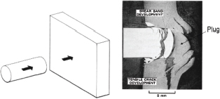
FIGURE 3-1 Impact on steel plate. Rod impacting a plate at 90 degrees (left), and cross section showing simple plugging of rolled homogeneous armor by shear instabilities and back surface spalling by nucleation, growth, and coalescence of voids and cracks (right). SOURCE: Erlich, D.C., L. Seaman, D.A. Shockey, and D.R. Curran. 1980. Development and Application of a Computational Shear Band Mode. Menlo Park, Calif.: SRI International.
Other failure modes may be invoked at higher velocities. Figure 3-2 shows a polished and etched cross section through the crater in a 1-in.-thick steel plate that has been impacted at 6 km/s by a 12.7-mm-diameter polycarbonate sphere.2,3 Adiabatic4 shear bands can be seen as white-etching bands of hard, untempered martensite extending into the plate (1), surfaces of strain localization that look like bands when seen edge-on. The path of the bands is followed by brittle cracks (2), which intersect with other cracks and liberate fragments. Just below the crater are spherical voids (3), a manifestation of ductile tensile failure; these are linked by shear bands. Homogeneous plastic flow (4) is made clear by the deviation of the process rolling lines from the horizontal. Ultimately, the hemispherical volume of dark-etching material just below the point of experienced α↔ε polymorphic phase change brought about by pressure (5). The grain size is refined and the transformed material is significantly hardened. The boundary of the dark-etching material is a 130 kbar isobar. Thus, five failure modes operated at once, with the stress relaxation effect of each mode affecting the behavior of the others.
The damage beneath the crater in Figure 3-2 is complex and seems at first nearly impossible to interpret, yet it reveals how the material is failing. Such damage “hieroglyphics” must nevertheless be read and understood in order to predict penetration behavior and design microstructures with enhanced protective capabilities. Key to developing a deeper understanding are laboratory experiments that isolate each specific damage mechanism. This would allow each failure mode to operate under a range of well-controlled rate, temperature, and stress state conditions, providing the opportunity to study and quantitatively describe its evolution by means of real-time observation or post-test analysis of tests interrupted at various stages of damage development.
Finding 3-1. Ballistic penetration of metals can occur by five failure modes—adiabatic shear bands, cracks, voids, plastic deformation, and phase changes—more than one or all of which can occur simultaneously.
______________
2Shockey, D.A., D.R. Curran, and P.S. DeCarli. 1975. Damage in steel plates from hypervelocity impact, I: Physical changes and effects of projectile material. Journal of Applied Physics 46(9): 3766-3775.
3Bertholf, L.D., L.D. Buxton, B.J. Thorne, R.K. Byers, A.L. Stevens, and S.L. Thompson. 1975. Damage in steel plates from hypervelocity impact II: Numerical results and spall measurement. Journal of Applied Physics 46(9): 3776-3783.
4“Adiabatic” refers to any process which occurs without heat transfer.
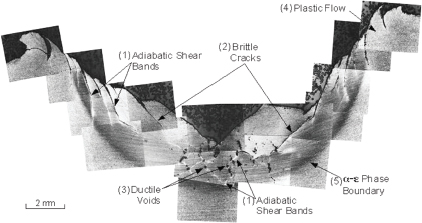
FIGURE 3-2 Polished and etched cross section through the crater in a steel plate that was impacted at 6 km/s by a 12.7-mm-diameter polycarbonate sphere. Five damage modes operated. SOURCE: Reprinted with permission from Shockey, D.A., D.R. Curran, and P.S. De Carli, Journal of Applied Physics, 46, 3766, (1975). Copyright 1975, American Institute of Physics.
PENETRATION MECHANISMS IN CERAMICS AND GLASSES
Penetration of thick sections of ceramics and glasses occurs by damaging the target material at the leading surface of the projectile and then pushing the damaged material out of the projectile path.5 Here, too, an understanding of the damage mechanisms is key to developing ceramics and glasses with improved ballistic performance.
The damage mechanisms are readily revealed in experiments in which the projectile does not penetrate—that is, at velocities and test conditions sufficient to initiate the damage process but insufficient for ingress. Such tests produce ring cracks and radial cracks on the impacted surfaces, as well as the well-known Hertzian cone cracks, which extend into the target at divergent angles from the shot line. More important when considering penetration mechanisms, however, is the microdamage produced in the target directly ahead of the projectile, since it is the material in this location that must be extruded from the projectile path to permit penetration.
The polished cross sections taken through the shot lines after tests on SiC and TiB2 (Figure 3-3) show the Hertzian cone cracks and, often, an obvious zone of damaged material immediately beneath the impacting projectile.6
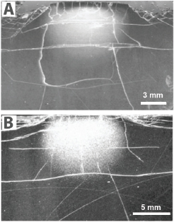
FIGURE 3-3 Polished cross sections through the shot line of a SiC (A) and a TiB2(B) target, showing typical microdamage immediately below the impact site after a no-penetration experiment with a long rod tungsten projectile. SOURCE: LaSalvia, J.C., and J.W. McCauley. 2010. Inelastic deformation mechanisms and damage in structural ceramics subjected to high-velocity impact. International Journal of Applied Ceramic Technology 7(5): 595-605. See also LaSalvia, J.C., R.B. Leavy, J.R. Houskamp, H.T. Miller, D.E. MacKenzie, and J. Campbell. 2010. Ballistic impact damage observations in a hot-pressed boron carbide. Pp. 45-55 in Advances in Ceramic Armor V. J.J. Swab, D. Singh, and J. Salem, eds. New York, N.Y.: John Wiley & Sons.
______________
5Shockey, D.A., A.H. Marchand, S.R. Skaggs, G.E. Cort, M.W. Burkett, and R. Parker. 1990. Failure phenomenology of confined ceramic targets and impacting rods. International Journal of Impact Engineering 9(3): 263-275. Also in Shockey, D.A., A.H. Marchand, S.R. Skaggs, G.E. Cort, M.W. Burkett, and R. Parker. 2002. Failure phenomenology of confined ceramic targets and impacting rods. Pp. 385-402 in Ceramic Armor Materials by Design, Ceramics Transactions Column 134. J.W. McCauley, A. Rajendran, W. Gooch, S. Bless, S. Wax, and A. Crowson, eds. Westerville, Ohio: The American Ceramic Society.
6LaSalvia, J.C., and J.W. McCauley. 2010. Inelastic deformation mechanisms and damage in structural ceramics subjected to high-velocity impact. International Journal of Applied Ceramic Technology 7(5): 595-605. See also LaSalvia, J.C., R.B. Leavy, J.R. Houskamp, H.T. Miller, D.E. MacKenzie, and J. Campbell. 2010. Ballistic impact damage observations in a
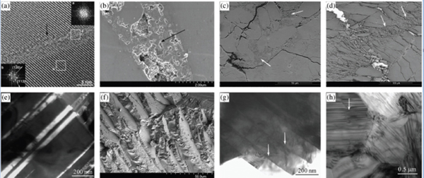
FIGURE 3-4 Damage mechanisms (see arrows) observed in several ceramics: Nanoscale amorphization bands in ballistic-generated B4C fragments (a); shear “band” in a sphere-impacted B4C (b); shear-induced amorphization in a sphere-impacted b-SiC (c); multiscale fragmentation and shear localization in the same material (d); twins in sintered Al2O3 shocked above its Hugoniot elastic limit (e); aluminum oxynitride (AlON) fracture surface showing multiscale cleavage (f); AlON fragment showing microcleavage (g); and stacking faults in a SiC (h). SOURCE: LaSalvia, J.C., and J.W. McCauley. 2010. Inelastic deformation mechanisms and damage in structural ceramics subjected to high-velocity impact. International Journal of Applied Ceramic Technology 7(5): 595-605. See also LaSalvia, J.C., R.B. Leavy, J.R. Houskamp, H.T. Miller, D.E. MacKenzie, and J. Campbell. 2010. Ballistic impact damage observations in a hot-pressed boron carbide. Pp. 45-55 in Advances in Ceramic Armor V. J.J. Swab, D. Singh, and J. Salem, eds. New York, N.Y.: John Wiley & Sons.
Closer examination of the damage zone, known as the Mescall zone (MZ),7 provides valuable details of the material failure process. Figure 3-4 shows the variety of damage mechanisms observed beneath the projectile impact sites in several ceramics. These mechanisms include intergranular and transgranular macro- and microcracking; shear localization; solid-state amorphization; dislocation activity; twinning; stacking faults; and phase transformations.8
The damage process requires some time, typically 1-3 μs, and can be observed with high-speed photography. Penetration can proceed only after material in the MZ has failed and has been pushed from the projectile path. Thus the projectile dwells on the target surface before beginning to penetrate. If a projectile did not reach a certain velocity—the transition velocity—and if the ceramic held together sufficiently—that is, if it exhibited “target confinement”—the projectile would not penetrate and “interface defeat” would be said to have occurred.
Projectiles with sufficient kinetic energy to fully develop the MZ penetrate by continuously damaging the target material at the projectile tip and extruding the fragments to the side of the shot line. Insight into the extrusion process is obtained by examining cross sections of partially penetrated target blocks. Monolithic targets of a soda lime glass impacted by a hemi-nosed steel rod at velocities sufficient to penetrate partway through the target9 retain the cracking pattern and fragments produced during penetration (Figure 3-5a). The cracks and fragments are revealed by infiltrating a damaged target with a low-viscosity epoxy, then sectioning the target with a diamond saw, usually on a plane through the shot line. Next, the surfaces of section are polished and examined by optical and scanning electron mi-
______________
hot-pressed boron carbide. Pp. 45-55 in Advances in Ceramic Armor V. J.J. Swab, D. Singh, and J. Salem, eds. New York, N.Y.: John Wiley & Sons.
7The Mescall zone—first defined in Shockey, D.A., A.H. Marchand, S.R. Skaggs, G.E. Cort, M.W. Burkett, and R. Parker. 1990. Failure phenomenology of confined ceramic targets and impacting rods. International Journal of Impact Engineering 9(3): 263-275—is named after John Mescall, a scientist at the U.S. Army Materials and Mechanics Research Center, who deduced the existence of the finely comminuted volume of target directly beneath the nose of an advancing projectile from his computational simulations (Mescall, J., and C. Tracy. 1986. Improved modeling of fracture in ceramic armors. Pp. 41-54 in Army Science Conference Proceedings, 17-19 June 1986, Volume III. Washington, D.C.: Department of the Army, Deputy Chief of Staff for Research, Development & Acquisition; Mescall, J., and V. Weiss. 1983. Materials Behavior under High Stress and Ultrahigh Loading Rates. New York, N.Y.: Plenum Press).
8LaSalvia, J.C., and J.W. McCauley. 2010. Inelastic deformation mechanisms and damage in structural ceramics subjected to high-velocity impact. International Journal of Applied Ceramic Technology 7(5): 595-605. See also LaSalvia, J.C., R.B. Leavy, J.R. Houskamp, H.T. Miller, D.E. MacKenzie, and J. Campbell. 2010. Ballistic impact damage observations in a hot-pressed boron carbide. Pp. 45-55 in Advances in Ceramic Armor V. J.J. Swab, D. Singh, and J. Salem, eds. New York, N.Y.: John Wiley & Sons.
9Shockey, D.A., D. Bergmannshoff, D.R. Curran, and J.W. Simons. 2008. Physics of glass failure during rod penetration. Pp. 23-32 in Advances in Ceramic Armor IV:Ceramic Engineering and Science Proceedings, Volume 29, Issue 6. L.P. Franks, ed. Hoboken, N.J.: John Wiley & Sons.
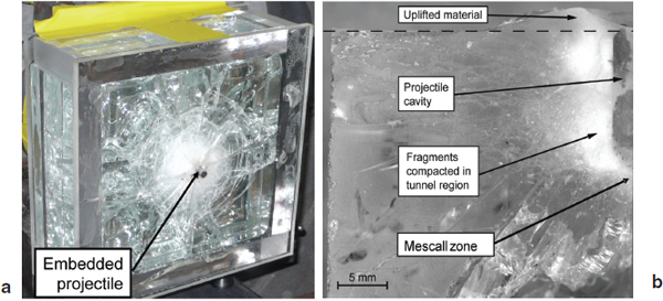
FIGURE 3-5 A 200 × 200 × 75 mm3 monolithic soda lime glass target (confined on all sides with polymethyl methacrylate plates) partially penetrated by a 31.75 × 6.35-mm-diameter heminosed steel rod impacting at 300 m/s (a); a surface of section through the shot line showing damage around the projectile cavity (b). SOURCE: Shockey, D., J. Simons, and D. Curran. 2010. The damage mechanism route to better armor materials. International Journal of Applied Ceramic Technology 7(5): 566-573.
croscopy to observe cracking details and the size and shapes of fragments (Figure 3-5b).
Glass and ceramic targets show the radial cracks, ring cracks, cone cracks, and lateral cracks typical of a rod or particle impact. Target fragments about one to three projectile radii in diameter form a cylindrical zone (tunnel) surrounding the embedded projectile. An uplifted “lip” of material is often produced at the impact surface. The size and shape of MZ fragments can be determined and quantified by examining petrographic sections through the tunnel debris. The MZ of highly comminuted material at the leading edge of the penetrator shown in Figure 3-5b is smaller than what would be expected during penetration because the stresses at the tip of an arresting penetrator are smaller than those in advance of a moving penetrator.
The fragmentation and cracking patterns suggest that material ahead of the projectile is loaded, damaged, and displaced in three successive steps under consecutive tensile-, shear-, and compression-dominated stress states (Figure 3-6). A material element in the path of an advancing penetrator initially experiences tension and develops closely spaced cone cracks running at acute angles to the penetration direction. Subsequent lateral cracks break up the material between adjacent cone cracks. As the projectile moves closer, a local volume (about the size of the projectile nose) of the cracked material is overrun by a low-confinement field of high shear and is comminuted into fine fragments. Third, the projectile imposes high pressure and extrudes the comminuted material into the cracked and coarsely fragmented tunnel and to the sides of the projectile nose.
Finding 3-2. An examination of the mechanics of penetration in brittle materials reveals four important characteristics of microstructures that are key for improved body armor materials. The structures must (1) resist deformation and macro (cone and lateral) cracking; (2) be more difficult to comminute; (3) break into fragment geometries that are more resistant to flow; and (4) form more dilatant fragment beds.10
PENETRATION MECHANISMS IN POLYMERIC MATERIALS
Polymers such as polycarbonate are often used in armor systems as backing plates (spall shields), as intermediate layers in a laminated glass or ceramic system, as a scratch-tolerant front plate, or as a matrix to embed strong fibers.
Because the material failure mechanisms are sensitive to boundary conditions, they are somewhat determined by the application. Real-time observation with high-speed cameras shows that the penetration of polycarbonate plates by cylindrical projectiles occurs by elastic dishing, petalling, cone cracking, and plugging.11 The projectile initially indents the surface of the plate, causing the distal plate surface to bulge and shear yielding around the impact site. As the penetrator advances, cracks form ahead of it. Depending on the projec-
______________
10Shockey, D.A., J.W. Simons, and D.R. Curran. 2010. The damage mechanism route to better armor materials. International Journal of Applied Ceramic Technology 7(5):566-573.
11Wright, S.C., N.A. Fleck, and W.J. Stronge. 1993. Ballistic impact of polycarbonate:An experimental investigation. International Journal of Impact Engineering 13(1):1-20.
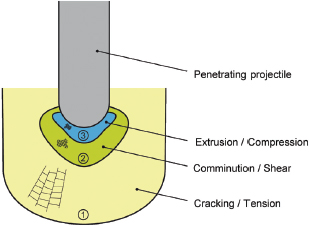
FIGURE 3-6 Three material processing zones and three stress states experienced by a material element in the path of an advancing penetrator. SOURCE: Shockey, D., J. Simons, and D. Curran. 2010. The damage mechanism route to better armor materials. International Journal of Applied Ceramic Technology 7(5): 566-573.
tile nose shape, plate perforation occurs by petalling or by plugging—that is, by pushing a cylinder of material ahead of the projectile through the distal plate surface. Evidence of melting has been observed. Material failure mechanisms may include tensile failure by nucleation, growth, and coalescence of planar cracks, spherelike voids, and shear instabilities. In glassy polymers, crazing, or the formation of oriented fibrils and intervening voids, is a common precursor to crack formation and tensile failure.
Polymer fibers are used in ballistic materials and as reinforcing elements in composite materials. A careful and detailed study of nanoscale failure phenomenology would be most useful in developing fibers with better ballistic performance. Figure 3-7 shows a fabric after it has been impacted by a platelike projectile.12 The failure mechanisms of polymer fibers can be determined by examining the severed fiber ends with a scanning electron microscope (SEM).13 For example, the internal structure of a 20-μ-diameter polyp-phenylene benzobisthiazole (PBZT) fiber consists of large length-to-width, ribbonlike fibrils typically 1 μ wide, which in turn are made up of microfibrils of similar geometry but only a few nanometers wide (Figure 3-8). Figure 3-9 indicates that tensile fracture first occurred at defects such as voids and kinks and was assisted by the residual stresses that arose during processing.14
While the details of the tensile failure mechanism are not well known, high magnification shows that the fibrils in the fibers are stretched, suggesting tensile failure analogous to that seen in tensile tests of metals. Fiber material very likely undergoes homogeneous plastic deformation and localized plastic deformation in much the same way as metals; failure may also occur by the nucleation of voids, cracks, and shear bands.
It is not understood how the material microstructure at this level (the nano level) influences the deformation, localization, and failure behavior of the material. Failure initiators are thought to originate in material defects such as tiny voids, foreign particles, and chain entanglements (shown in Figure 3-10) resulting from chemical inhomogeneities or processing procedures.
Fiber failure modes other than tensile failure are also observed. For example, a projectile’s impact on fabric backed with a stiff plate of ceramic compresses the fabric against the backing and causes transverse loads on the yarns and fibers that can result in deformation and failure. When compressed fibers are examined by SEM, they and the fibrils show flattening, kinking, and buckling.
Finding 3-3. The influence of the nano- and microstructure of polymeric materials on the deformation, localization, and failure behavior of the materials is not well understood, especially at high strain rates and high pressures.
Finding 3-4. Closing the large gap between the currently attainable and the theoretical strengths of fibers would benefit greatly from studies of ballistically (and quasi-statically) failed fibers at the nano- and micro levels to determine the mechanism(s) of material failure and identify the nanostructural features initiating the failure process or otherwise assisting it.
FAILURE MECHANISMS IN CELLULAR-SANDWICH MATERIALS DUE TO BLASTS
A cellular material sandwiched between two faceplates provides mass-efficient protection against blast loads. The structure absorbs energy and reduces the transmitted force as the walls of each cell deform and fail. Thus, to improve or tailor the response of cellular structures to blast loads, cell failure mechanisms must be understood.
Cellular materials include polymers, ceramics, and metals and metal foams; cell geometries include honeycomb and other lattices as well as stochastically random geometries. Several material properties contribute to the effective absorp-
______________
12Shockey, D.A., D.C. Erlich, and J.W. Simons. 2004. Lightweight Ballistic Protection of Flight-Critical Components on Commercial Aircraft, Part 2: Large-Scale Ballistic Impact Tests and Computational Simulations, DOT/FAA/AR-04/45,P2. Available online at http://www.tc.faa.gov/its/worldpac/techrpt/ar04-45p2.pdf. Last accessed April 15, 2011.
13Hearle, J.W.S., B. Lomas, and W.D. Cooke. 1998. Atlas of Fibre Fracture and Damage to Textiles. Boca Raton, Fla.: CRC Press.
14Allen, S.R., A.G. Filippov, R.J. Farris, and E.L. Thomas. 1981. Macro-structure and mechanical behavior of fibers of poly-p-phenylene benzobisthiazole. Journal of Applied Polymer Science 26(1): 291-301.
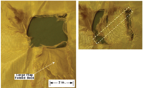
FIGURE 3-7 Post-test observation of fabric damage from a platelike projectile showing yarn breakage characteristics (left); the projectile size is shown with the fabric flap in its original position (right). SOURCE: Shockey, D.A., D.C. Erlich, and J. W. Simons. 2004. Lightweight Ballistic Protection of Flight-Critical Components on Commercial Aircraft, Part 2: Large-Scale Ballistic Impact Tests and Computational Simulations, DOT/FAA/AR-04/45,P2. Available online at http://www.tc.faa.gov/its/worldpac/techrpt/ar04-45p2.pdf. Last accessed April 15, 2011.

FIGURE 3-8 SEM micrograph revealing fibrillar microstructure in an as-spun PBZT fiber. SOURCE: Allen, S.R. 1983. Mechanical and morphological correlations in poly-(p-phenylene benzobisthiazole) fibers. Ph.D. Dissertation. Amherst, Mass.: University of Massachusetts.
tion of the energies of blast loads. These properties include the elastic stiffness, the yield strength, strain hardening, and the level of plateau stress at which a material compresses plastically.
In foams of ductile aluminum, discrete bands of collapsed cells establish the onset of yielding, the hardening, and the level of the plateau stress (Figure 3-10).15When the load is applied slowly, the bands form progressively and independently; at higher loading rates the cellular structure deforms by the advancement of a crush front from the impact surface.16
FIGURE 3-11 shows three specific failure mechanisms operating sequentially in a ductile aluminum cell under a quasi-static load.17 First, localized plastic straining occurs at a cell node.
Next, the cell membrane plastically buckles. Finally, the cell collapses. Blast-loaded aluminum foam may fail in
______________
15Bastawros, A.-F., H. Bart-Smith, and A.G. Evans. 2000. Experimental analysis of deformation mechanisms in a closed-cell aluminum alloy foam. Journal of the Mechanics and Physics of Solids 48(2): 301-322.
16Tan, P.J., S.R. Reid, J.J. Harrigan, Z. Zou, and S. Li. 2005. Dynamic compressive strength properties of aluminum foams Part I: Experimental data and observations. Journal of the Mechanics and Physics of Solids 53(10): 2174-2205.
17Bastawros, A.-F., H. Bart-Smith, and A.G. Evans. 2000. Experimental analysis of deformation mechanisms in a closed-cell aluminum alloy foam. Journal of the Mechanics and Physics of Solids 48(2): 301-322.
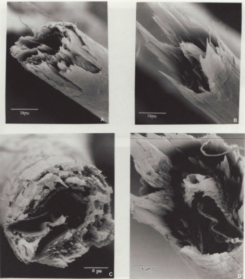
FIGURE 3-9 SEM side views (A,B) and end-on views (C,D) of matching fracture ends of a tensile-fractured PBZT fiber. SOURCE: Allen, S.R. 1983. Mechanical and morphological correlations in poly-(p-phenylene benzobisthiazole) fibers. Ph.D. Dissertation. Amherst, Mass.: University of Massachusetts.
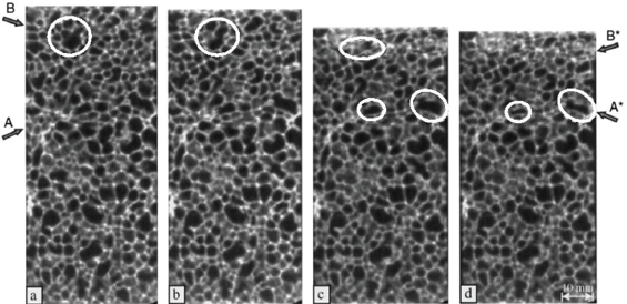
FIGURE 3-10 Sequence of computerized axial tomography scan images showing macro deformation bands in quasi-static compression-loaded ductile aluminum foam. (Dominant bands are identified with arrows, and the cells most visibly subjected to distortion are circled.) Note the buckling deformations exhibited by one of the membranes in each cell. SOURCE:Bastawros, A.-F., H. Bart-Smith, and A.G. Evans. 2000. Experimental analysis of deformation mechanisms in a closed-cell aluminum alloy foam. Journal of the Mechanics and Physics of Solids 48(2): 301-322.
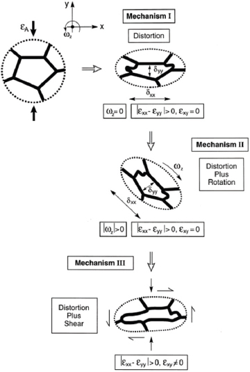
FIGURE 3-11 Sequential mechanisms responsible for cell collapse in ductile aluminum foam under quasi-static load. SOURCE: Bastawros, A.-F., H. Bart-Smith, and A.G. Evans. 2000. Experimental analysis of deformation mechanisms in a closed-cell aluminum alloy foam. Journal of the Mechanics and Physics of Solids 48(2): 301-322.
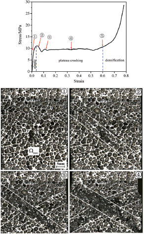
FIGURE 3-12 Stress-strain curve for a brittle aluminum foam subjected to quasi-static compression (top). Bands of fractured cells after imposed quasi-static engineering compressive strains of 0, 5.6 percent, 11.7 percent, 33.3 percent, and 60 percent, respectively (lower four images). SOURCE: Song, H-W., Q-J. He, J-J. Xie, and A. Tobota. 2008. Fracture mechanisms and size effects of brittle metallic foams: In situ compression tests inside SEM. Composites Science and Technology 68(12): 2441-2450.
tension18 owing to a reflected tensile stress wave or recoil after compaction.
Brittle metallic foams fail at the macroscopic level by forming fracture bands similar to the deformation bands in ductile aluminum (Figure 3-12). Compression, tension, and shear cause cell walls to crack; friction and shear operate between fractured cells. At the cell membrane level, failure is by the brittle cracking of cell walls under compression, tension, and shear and by friction and shear between fractured cells (Figure 3-13).19
Finding 3-5. Cellular materials absorb blast energy by deformation and failure of cell walls.
This brief survey of how materials undergo penetration shows that
- Penetration occurs by material failure;
______________
18Langdon, G.S., D. Karagiozova, M.D. Theobald, G.N. Nurick, G. Lu, and R.P. Merrett. Fracture of aluminum foam core sacrificial cladding subjected to air-blast loading. International Journal of Impact Engineering 37(6): 638-651.
19Song, H-W., Q-J. He, J-J. Xie, and A. Tobota. 2008. Fracture mechanisms and size effects of brittle metallic foams: In situ compression tests inside SEM. Composites Science and Technology 68(12): 2441-2450.
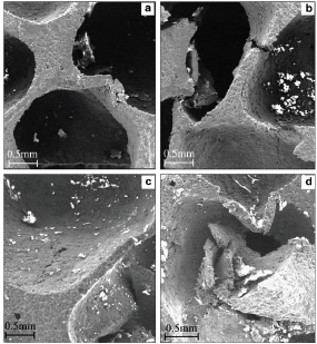
FIGURE 3-13 SEM images of failed cells in brittle aluminum foam showing failure modes (a) under compression, (b) tension and shear, (c) face cracking, and (d) friction and shear between fractured cells. SOURCE: Song, H-W., Q-J. He, J-J. Xie, and A. Tobota. 2008. Fracture mechanisms and size effects of brittle metallic foams: In situ compression tests inside SEM. Composites Science and Technology 68(12): 2441-2450.
- Material failure occurs at the microstructural level, including the chemical phase and phase composition, and the nanostructural level;
- Failure can occur in five modes—adiabatic shear bands, cracks, voids, plastic deformation, and phase changes—more than one of which can occur simultaneously;
- Material failure is a kinetic process, involving nucleation, growth, and coalescence of these failure modes; and
- Cellular materials absorb blast energy by deformation and failure of cell walls.
Recommendation 3-1. Organizations and individuals engaged in developing protection materials should seek to maximize penetration resistance. A comprehensive methodology for this should entail the following:
- Using the understanding of how armor materials fail to suggest possible microstructures—that is, those microstructures discovered through experimental/computational investigations as well as those identified during manufacturing trials that may oppose damage development;
- Designing microstructures that inhibit, disrupt, or avoid altogether the failure mechanisms operating in armor during projectile attack;
- Developing innovative laboratory tests that invoke the pertinent damage mechanisms;
- Designing tests so as to favor only one mechanism and so avoid the complication of several mechanisms operating simultaneously and influencing each other.
- Designing other tests that invoke two or more mechanisms, to investigate synergistic effects. Such tests must be conducted under well-controlled and monitored conditions of load, rate, and temperature and need to measure the governing (nonconventional) material failure properties;
- Performing other tests in which the load application is stopped at various percentages of the maximum load and the specimens sectioned and examined microscopically to observe the damage at increasing stages of development and the interaction of the damage with microstructural features;
- Prescribing microstructures that repress or interfere with failure mechanisms and interacting with processing engineers to innovate ways to achieve these microstructures;
- Choosing and implementing chemistries and processing routes;
- Performing laboratory tests and ballistic tests, noting results, adjusting initial thoughts, and exploring a second generation of chemistries and processing; and
- Continuing iterations with the goal of achieving ever better protective materials.
The time and expense of developing a superior armor material can be greatly reduced if the response of a chosen microstructure to ballistic attack can be at least approximately predicted by means of a computational simulation. A material deformation and failure model based on observations of penetrated targets and quantified by parameters derived from laboratory tests can be expected to provide more reliable results than current models. To assist in constructing a computational model of damage evolution, damage features observed in the interrupted tests should be counted and measured as a function of location in the specimen (by determining a nucleation rate). These data can be correlated with a stress and strain history obtained by computational simulations of the tests in order to develop equations that describe damage development. These equations would constitute the computational materials damage model and could be used in finite element codes to compute damage evolution during target penetration.
Thus, achievement of improved protective materials necessitates that damage development be hindered, most likely by specifying microstructures that resist the nucleation, growth, and coalescence of cracks, voids, and shear bands and by specifying as well chemistries and processing routes to achieve those microstructures.
Recommendation 3-2. Organizations and individuals engaged in developing protection materials should
- Choose materials based on their ability to inhibit or avoid material failure mechanisms, as opposed to choosing materials based on their bulk properties.
- Formulate mathematical models of damage evolution and use these in computational simulations of ballistic penetration scenarios to assist and expedite the design of improved armor materials and systems.


