
5
Lightweight Protective Materials: Ceramics, Polymers, and Metals
The history of improving protection while reducing the weight of armor has been a remarkable materials success story. Over the last half-century, new choices of materials such as ceramics, polymers, and polymer fibers and lower density metals have significantly decreased the weight of the armor needed for the protection of personnel and vehicles. Figure 1-2 in Chapter 1 illustrates the revolutionary reductions in the areal density of vehicle armor as advanced materials have become available, starting with rolled homogeneous armor and advancing to complex composite systems. There have been similar advances in lightweight materials for personnel protection as well. As described in Chapter 2, armor systems are designed and fabricated using suitable combinations of ceramics, metals, polymers, fibers, and composites to meet specific threat requirements. The choice of materials, as well as their geometry and the means by which they are assembled, is a key factor in armor design. Each material component serves a specific purpose not only in defeating the kinetic energy of projectiles or mitigating a blast but also in maintaining the structural armor’s integrity.
To provide a basic understanding of current armor materials and to anticipate areas where there could be revolutionary improvements in armor materials, this chapter examines the synthesis and processing of each of the main types of materials, with particular emphasis on the resultant material structure from the atomic to the macro scale. Potential new compositions and the tailoring of microstructures to discover material behaviors that could dramatically enhance armor performance are highlighted, as are the challenges involved in achieving such advances.
The schematic in Figure 5-1 depicts a notional armor structure,1 consisting of both dense and porous ceramics, fibers, environmental coatings, polymer binders, and adhesive joints. The complex tile architecture presented in Figure 5-1 uses several materials and different assembly methods for those materials such that the layers perform their protective functions during the projectile impact. This chapter will examine how achieving improved material behavior but also minimizing manufacturing cost requires a deep scientific and engineering understanding of the desirable structures and compositions of advanced protective materials as well
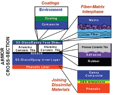
FIGURE 5-1 Schematic presentation of the cross section of an armor tile typically used for armored vehicles showing the complexity of the armor architecture. Different classes of materials, such as dense and porous ceramics, fiber composites, thermoplastic polymers, and adhesives are used for the tile assembly. DEA, diethanolamine. SOURCE:James W. McCauley, Chief Scientist, Weapons and Materials Research Directorate, Army Research Laboratory (ARL) fellow, ARL, “Armor Materials 101-501: Focus on Fundamental Issues Associated with Armor Ceramics ‘Kinetic energy passive armor,’” presentation to the committee on March 9, 2010.
______________
1James W. McCauley, Weapons and Materials Research Directorate, Army Research Laboratory (ARL) fellow, ARL, “Armor materials 101-501: Focus on fundamental issues associated with armor ceramics ‘kinetic energy passive armor,’” presentation to the committee, March 9, 2010.
as how to make and process them. That said, as explained in Chapter 3, the requisite material properties that are to be optimized cannot be measured by the usual quasi-static measures of mechanical behavior. However, even at lower strain rates, conducting mechanical tests at small scale—that is, at the microstructural level, on the order of nanometers or microns—will likely shed light on the deformation mechanisms under known loading states and can provide information that is very useful for parallel modeling efforts, keeping in mind that the ultimate goal is real-time measurements of many properties on ballistic timescales.
As shown in Chapter 4, the behavior of an assembly in the face of a particular threat is not the simple sum of the behaviors of its component parts. Thus, an integrated experimental and modeling approach that allows clear variation of crystal and material microstructures and subsequent high-rate dynamic characterization of the material behavior by itself and as part of an armor system may enable the development of ever lighter and more effective protection materials.
A more rapid development of materials and their successful insertion into armor necessitates attention to such basic issues as the reduction of voids and impurities along with attention to the challenges of advanced designs and creating and synthesizing new material compositions, new phases, and preferred microstructures. This chapter discusses the main issues surrounding several important classes of protection materials. The accompanying set of appendixes goes into considerable detail—especially on the synthesis and processing of ceramics, cermets, and polymers—because these classes of materials have the best potential for significant improvements if the interrelationships can be elucidated between synthesis, processing methods, and the resultant structures, along with the corresponding high-rate measurement of material behavior. For the reader to appreciate the issues, the selected materials are introduced at the atomic, molecular, micro, and macro scales before describing the synthesis and processing methods. Finally, areas of potential innovation that may bring transformational changes in the design and performance of armor materials are described, along with the challenges to be overcome.
High-temperature refractory ceramic materials offer a unique combination of physical and mechanical properties that in turn can offer favorable protection against high-velocity armor-piercing bullets (see Chapter 2). Ceramics feature high hardness, high elastic modulus, low density, sufficient flexure, and good compressive strengths, but relatively low fracture toughness. The Hugoniot elastic limit (HEL)—the maximum uniaxial dynamic stress that a material can withstand elastically—represents the nominal potential of a ceramic as an armor-grade material.2 However, it is almost mandatory for the candidate material to also possess a residual plastic behavior greater than the HEL, because the greatest velocity threats typically induce stresses that are higher than the HEL of materials that are commonly available. Properties such as hardness and modulus are determined by the chemical and phase compositions and microstructure of the material. Besides composition, many ceramic material properties can be influenced by the relative amounts of the various possible phases/polytypes, average grain size, grain-size distribution, and grain morphologies, as well as minor-phase content.
One of the most important aspects of ceramic materials that makes them suitable for ballistic protection is the strong covalent bonding between lightweight atoms located in the first quarter of the periodic table of elements. The elements include beryllium, boron, carbon, oxygen, magnesium, aluminum, and silicon. Indeed, the most developed and best explored armor ceramics are Al2O3 (aluminum oxide, or alumina), B4C (boron carbide), and SiC (silicon carbide). However, these three materials are but a small portion of the ceramics that could be used for armor application. For example, novel boron icosahedra containing higher borides, ternary B–C–Si and B–C–N systems, and homologous Al(Mg)–B–C(N) compounds have yet to be explored.
Because ceramics are relatively brittle materials, they are sensitive to flaws, and flaws adversely affect materials performance. If flaws are prevalent, it is often difficult or almost impossible to assess the intrinsic properties and behaviors of materials. Thus, it is critical to be able to process ceramics to near-theoretical maximum density, eliminating most of the void-type defects in order to explore the fundamental behavior. Such defects are often responsible for ceramic armor failure from the shock wave of a ballistic impact, which causes cracks to nucleate at the defect sites and then grow and coalesce, causing massive failure. As noted by Lankford,3the ceramic would never fail (in penetration) if it could be constrained such that it would undergo plastic flow. Of course the presence of defects will keep the ceramic from reaching the stress levels necessary to activate plasticity mechanisms, and simple, practical improvement in performance can be realized by employing nondestructive evaluation analysis to reveal the larger defects in the material. Better compaction technology and sintering techniques should result in a more uniform and higher density component. Upgrades in powder quality (purity, uniformity of particles) and improvements in the formulation of sintering aids can also help eliminate voids and porosity and retain homogeneous microstructure. Highly nonuniform grain-size distributions and the presence of grain boundary phases due to poor compositional quality of the starting powders can also adversely affect performance. Agglomerated particles
______________
2Fanchini, G., J.W. McCauley, and M. Chhowalla. 2006. Behavior of disordered boron carbide under stress. Physical Review Letters 97(6): Article number 035502.
3Lankford Jr., J. 2004. The role of dynamic material properties in the performance of ceramic armor. International Journal of Applied Ceramic Technology 1(3): 205-210.
due to poor mixing of sintering aids in the powders4,5 and extraneous carbon additions or poor mixing of the carbon reduce the grain growth of nearby SiC grains and leave large carbon inclusions inside the fine SiC matrix.6
Early in the Vietnam conflict, the Department of Defense (DoD) approached the Los Alamos National Laboratory and the Lawrence Livermore National Laboratory with a request for lightweight body armor for ground troops. John Taylor at Los Alamos and Mark Wilkins at Lawrence Livermore began investigating ceramics for protection against small arms fire. Coors Ceramics was asked to fabricate an alumina molded body panel, but ground troops in the jungles of Vietnam found it too heavy and would only wear the armor on guard duty at a fixed post. Later, Wilkins et al.7 demonstrated a relationship between hardness, compressive strength, and ballistic performance and showed that bulk properties alone were not a sufficient basis for the design of armor. They argued that some trade-off between the various properties would be necessary to derive benefits from other key properties such as fracture toughness and plasticity.8,9 Their early work eliminated most silicate-based ceramics from consideration owing to their low hardness and the fact that mullite and other alumina ceramics containing silicate seemed to fail under lesser ballistic attack than did high-purity alumina. Wilkins et al. further focused their research on other oxides such as aluminum magnesium spinel; carbides such as silicon and boron carbides; borides such as titanium diboride; and a few nitrides, including aluminum nitride. Alumina emerged as today’s most widely used ceramic armor, combining good mechanical behavior with relatively low cost. Because alumina is manufactured in quantities of millions of pounds throughout the world, it is much less expensive than either SiC or, especially, B4C. The densities of B4C (2.52 g/cm3) and SiC (3.29 g/cm3) are considerably less than that of Al2O3(3.98 g/cm3). However, because of its easy sinterability and the lower cost of the raw powders, alumina is still preferred for use in vehicle applications, where the extra weight can be tolerated, while the lighter B4C and SiC ceramics are now used in body armor.
Alumina nanoceramics that can reach the theoretical maximum density present an opportunity to probe the effects of microstructure on material behavior in a cost-effective material. While B4C and SiC ceramics require temperatures of 2150°C to 2200°C and, typically, applied pressure to carry out sintering to achieve to full density, alumina can be easily sintered into complex shapes to full density at 1500°C to 1600°C by pressureless sintering. Indeed, Al2O3 nanopowders can be sintered at 1100°C to 1200°C to full density while retaining their nanograin microstructure.10,11 Krell’s work on Al2O3indicated a Hall-Petch relationship, whereby decreasing the grain size yielded an increase in hardness.12 Chen et al.13 suggested the importance of effective plasticity on the ballistic behavior of alumina.
Of the other ceramics named above, SiC and B4C are the leading opaque ceramic materials for next-generation body and vehicle armor systems. Their favorable characteristics relative to alumina (Al2O3) are lighter weight, higher hardness, and higher stiffness.
A central tenet of materials science and engineering is that composition, crystal structure, and microstructure influence the mechanical behavior of the material. According to McCauley,14
… the fundamental factors that affect the intrinsic material characteristics [are] related to crystal physics, i.e., elastic properties and anisotropy, phase transformation, and deformation mechanisms along with the development of new materials and transformational processing methods [that can] yield large 25-40 percent improvements in ceramic performance.
A recent case in point is the great improvement in the mechanical performance of B4C-SiC layered particulate ceramics achieved by Orlovskaya et al. by introducing high compressive thermal residual stresses to their outer surface layer.15
______________
4Bakas, M., V.A. Greenhut, D.E. Niesz, J. Adams, and J. McCauley. 2003. Relationship between defects and dynamic failure in silicon carbide. Ceramic Engineering and Science Proceedings 24(3): 351-358.
5Bakas, M., V.A. Greenhut, D.E. Niesz, J. Adams, and J. McCauley. 2008. Relationship between defects and dynamic failure in silicon carbide. Chapter 52 in 27th Annual Cocoa Beach Conference on Advanced Ceramics and Composites: A: Ceramic Engineering and Science Proceedings, Volume 24, Issue 3. W.M. Kriven and H.-T. Lin, eds. Hoboken, N.J.: John Wiley & Sons.
6Raczka, M., G. Gorny, L. Stobierski, and K. Rozniatowski. 2001. Effect of carbon content on the microstructure and properties of silicon carbide-based sinters. Materials Characterization 46(2-3): 245-249.
7Wilkins, M.L., C.F. Cline and C.A. Honodel. 1969. Light Armor, UCRL-71817, July 23. Livermore, Calif.: Lawrence Radiation Laboratory, University of California.
8Ibid.
9Wilkins, M.L., R.L. Landingham, and C.A. Honodel. 1971. Fifth Progress Report of Light Armor Program, UCRL-50980, January. Livermore, Calif.: Lawrence Radiation Laboratory, University of California.
10Krell, A. 1996. The influence of shaping method on the grain size dependence of strength in dense submicrometre alumina. Journal of the European Ceramic Society 16(11): 1189-1200.
11Bakas, M., V.A. Greenhut, D.E. Niesz, J. Adams, and J. McCauley. 2003. Relationship between defects and dynamic failure in silicon carbide. Ceramic Engineering and Science Proceedings 24(3): 351-358.
12Krell, A., P. Blank, H.W. Ma, T. Hutzler, and M. Nebelung. Processing of high-density submicrometer Al2O3 for new applications. Journal of the American Ceramic Society 86(4): 546-553.
13Chen, M.W., J.W. McCauley, D.P. Dandekar, and N.K. Bourne. 2006. Dynamic plasticity and failure of high-purity alumina under shock loading. Nature Materials 5(8): 614-618.
14James W. McCauley, Weapons and Materials Research Directorate, Army Research Laboratory (ARL) fellow, ARL, “Armor materials 101-501: Focus on fundamental issues associated with armor ceramics ‘kinetic energy passive armor,’” presentation to the committee, March 9, 2010.
15Orlovskaya, N., M. Lugovy, V. Subbotin, O. Radchenko, J. Adams, M. Chheda, J. Shih, J. Sankar, and S. Yarmolenko. 2005. Robust design and manufacturing of ceramic laminates with controlled thermal residual stresses for enhanced toughness. Journal of Materials Science 40(20): 5483-5490.
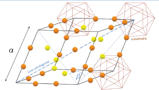
FIGURE 5-2 Rhombohedral unit cell structure of B4C showing B11C icosahedra and the diagonal chain of C–B–C atoms. Boron atoms are represented as red spheres and carbon atoms as white spheres.
Crystalline Ceramics: Phase Behavior, Grain Size or Morphology, and Grain Boundary Phases
Chemical composition, crystalline structure, and stability under elevated temperatures and under stress play an important role in determining both the quasi-static properties of these materials and their dynamic deformation and failure behavior. An examination of B4C and SiC will give readers a sense of the complexity of the atomic bonding and crystalline unit cells in these simple binary ceramics and will introduce them to intrinsic crystal defects such as stacking faults, twins, and grain boundaries, which they need to know about to understand some aspects of the ballistic performance of these two important protection materials.
Crystal Structure of Boron Carbide
Because it is not possible to precisely control the stoichiometry of boron carbide in commercially synthesized powders, it is important to understand how composition influences the atomic structure and the corresponding microstructure and properties. Boron carbide can be considered as a prototype of the interstitial compounds of rhombohedral boron, which include B12C, B12C2Al, B12S, B12O2, B12As2, B12P2, B3Si, and B4Si. Interestingly, the stoichiometric compound B4C does not exist, and the denomination “boron carbide” refers to the whole homogeneity range extending from B4.3C at the carbon-rich limit to B~11C at the boron-rich limit,16 a range of 8.8 mol percent to approximately 20 mol percent C. None of the unit cells of the interstitial compounds can be defined precisely. Instead, the materials are made up of composition-dependent, statistically distributed, and nearly isomorphous elementary cells, whose commonality is the 12-atom slightly distorted icosahedra at each cell vertex and the mostly 3-atom linear chains on the main diagonal parallel to the crystallographic c-axis. The unit cells thus comprise B12 and B11C icosahedra, while the chains comprise C–B–C, C–B–B, or B–![]() –B (the symbol
–B (the symbol![]() –indicates an atom vacancy) since the similarly sized C and B atoms readily substitute for each other. The general structure formula is (B12)n(B11C)1-n(CBC)p(CBB)q(B–
–indicates an atom vacancy) since the similarly sized C and B atoms readily substitute for each other. The general structure formula is (B12)n(B11C)1-n(CBC)p(CBB)q(B–![]() –B)1-p-q.17 The second constituentfor example, C, Al, or Ooccupies sites on the diagonal chain (see the unit cell shown in Figure 5-2).18 For the approximately stoichiometric B4C material, the icosahedra are B11C and the chains are C–B–C. Boron carbide (13.3 mol percent C) melts congruently at 2490°C and forms a eutectic mixture with carbon at 2375°C–2400°C at a composition of 29 mol percent C (see the B–C phase diagram, Figure 5-3).19 The extremely rigid framework arises from the covalently bonded icosahedra and the chain units of co-
–B)1-p-q.17 The second constituentfor example, C, Al, or Ooccupies sites on the diagonal chain (see the unit cell shown in Figure 5-2).18 For the approximately stoichiometric B4C material, the icosahedra are B11C and the chains are C–B–C. Boron carbide (13.3 mol percent C) melts congruently at 2490°C and forms a eutectic mixture with carbon at 2375°C–2400°C at a composition of 29 mol percent C (see the B–C phase diagram, Figure 5-3).19 The extremely rigid framework arises from the covalently bonded icosahedra and the chain units of co-
______________
16Kuck, S., and H. Werheit. 2000. Boron Compounds. Pp. 1-491 in Non-Tetrahedrally Bonded Binary Compounds II, Landolt-B?rnstein: Numerical Data and Functional Relationships in Science and Technology, New Series, subvolume 41. D. O. Madelung, ed. New York, N.Y.: Springer.
17Werheit,H., H.W. Rotter, S. Shalamberidze, A. Leithe-Jasper, and T. Tanaka. 2010. Gap-state related photoluminescence in boron carbide. Physica Status Solidi B 1-5. Available online at http://onlinelibrary.wiley.com/doi/10.1002/pssb.201046342/pdf. Last accessed March 31, 2011.
18Emin, D. 1988. Structure and single-phase regime of boron carbides. Physical Review B 38(9): 6041-6055.
19Thevenot, F. 1990. Boron carbide: A comprehensive review. Journal of the European Ceramic Society 6(4): 205-225.
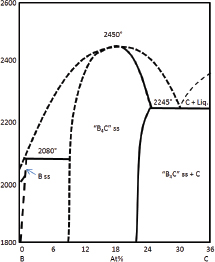
FIGURE 5-3 The boron-carbon phase diagram over the range 0-36 at % carbon. The cross-hatched region is commonly referred to as “B4C.” Different phase diagrams for the B–C system were reported in the past and there is no currently agreed upon reference phase diagram that can be reliably used to determine the correct stoichiometry and equilibrium phases.
valently bonded atoms and is responsible for the material’s refractory nature and extreme hardness.20
The average structure, measured by x-ray diffraction pattern or by nuclear magnetic resonance, varies as the boron content is varied.21 The theoretical density increases linearly with increasing carbon content, extending from 2.465 g/cm3 for B10.4C to 2.52 g/cm3 for B4C. Kwei et al.22 showed theoretically that the central boron atom in the C–B–C chain is relatively loosely held and that these locations can form vacancies along the three-atom chain, leading to a decrease in thermal conductivity.23 Aselage et al. found a significant drop in elastic modulus when the carbon concentration fell below 13.3 percent, reflecting a change in stiffness of the most compressible structural unit, the icosahedra (when B11C →B12). Very little is known about (1) the relative ratio of B12, B11C, and C–B–C, C–B–B, B–![]() –B structural units in boron carbide or (2) the rates of growth of the different crystal structures and their mutual transformations in the solid state as a function of pressure, temperature, and time.
–B structural units in boron carbide or (2) the rates of growth of the different crystal structures and their mutual transformations in the solid state as a function of pressure, temperature, and time.
The current working-phase diagram (Figure 5-3) for boron carbide shows that it is not a so-called line compound.24,25 Moreover, the details of the phase boundaries and relative amounts of the polytypes have not yet been firmly established.
Boron Carbide Amorphization
The maximum contact pressure generated by a projectile incident on a ceramic depends on the velocity, bulk modulus, density, and yield strength of the projectile.26 The impact can also lead to a rapid increase in the local temperature. When the pressure and/or the temperature exceeds a critical threshold, amorphization (the transition from the crystalline phase to the amorphous phase) or other phase transformations (crystal A to crystal B) can occur in certain materials. Boron carbide possesses the highest HEL of ceramic materials (~17-20 GPa), surpassing all of its denser competitors such as silicon carbide and alumina by a factor of 2.27,28,29 High HEL would suggest that boron carbide could outperform other armor materials. However, when the impact pressures exceed 20 GPa, an abrupt drop in shear strength occurs, leading to a much lower dynamic performance for B4C than that expected from its hardness and HEL.30,31The loss in performance of B4C under high-velocity impact is currently believed to be related to the formation of amorphous bands inside the crystalline grains and a related weakening of the bonds. These amorphous bands were discovered using high-resolution transmission electron microscopy (TEM) to analyze fragments of B4C ballistic tiles that had previously been subjected to supercritical impact velocities and pressures (in excess of 20-23 GPa). TEM images revealed the formation of 2-3-nm-wide intragranular amorphous bands that occur parallel to specific crystallographic planes and contiguously with apparent cleaved fracture surfaces (see Figure 5-4). At subcritical impact velocities, the amorphous bands were never observed; instead, a relatively high concentration of
______________
20Schwetz, K.A. 1999. Boron carbide, boron nitride, and metal boride. In Ullmann’s Encyclopedia of Industrial Chemistry, Sixth Edition (electronic release). T. Kellersohn, ed. Weinheim, Germany: Wiley-VCH Verlag.
21Werheit, H., H.W. Rotter, S. Shalamberidze, A. Leithe-Jasper, and T. Tanaka. 2010. Gap-state related photoluminescence in boron carbide. Physica Status Solidi B 1-5. Available online at http://onlinelibrary.wiley.com/doi/10.1002/pssb.201046342/pdf. Last accessed March 31, 2011.
22Kwei, G.H., and B. Morosin. 1996. Structures of the boron-rich boron carbides from neutron powder diffraction: Implications for the nature of the inter-icosahedral chains. Journal of Physical Chemistry 100(19): 8031-8039.
23Ibid.
24Emin, D. 1988. Structure and single-phase regime of boron carbides. Physical Review B 38(9): 6041-6055.
25Thevenot, F. 1990. Boron carbide: A comprehensive review. Journal of the European Ceramic Society 6(4): 205-225.
26Lundberg, P., R. Renstrom, and L. Westerling. 2002. Transition between interface defeat and penetration for a given combination of projectile and ceramic material. Ceramic Transactions 134: 173-181.
27Bourne, N.K. 2002. Shock–induced brittle failure of boron carbide. Proceedings of the Royal Society A: Mathematical, Physical & Engineering Sciences 458(2024):1999-2006.
28Johnson, G.R., and T.J. Holmquist. 1999. Response of boron carbide subjected to large strains, high strain rates, and high pressures. Journal of Applied Physics 85(12): 8060-8073.
29Thevenot, F. 1990. Boron carbide: A comprehensive review. Journal of the European Ceramic Society 6(4): 205-225.
30Bourne, N.K. 2002. Shock–induced brittle failure of boron carbide. Proceedings of the Royal Society A: Mathematical, Physical & Engineering Sciences 458(2024):1999-2006.
31Dandekar, D.P. 2001. Shock Response of Boron Carbide, ARLTR-2456. Available online at http://www.arl.army.mil/arlreports/2001/ARL-TR-2456.pdf. Last accessed April 7, 2011.
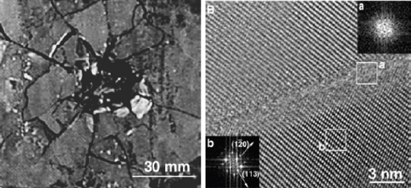
FIGURE 5-4 A boron carbide ballistic target that comminuted during impact (left) and a high-resolution TEM image of a fragment produced by a ballistic test at an impact pressure of 23.3 GPa (right). The lattice images on either side of the band correspond to the [-101] direction of crystalline B4C, and the loss of lattice fringes in the band indicates localized amorphization in a band within the grain. SOURCE: Chen, M., J. McCauley, and K. Hemker. 2003. Shock-induced localized amorphization in boron carbide. Science 299(5612): 1563-1566.
stacking faults and microtwins was observed, suggestive of plastic deformation of the material under shock loading.32
Understanding the pressure dependence of boron carbide phases would shed light on the issue of the pressure-induced, crystal-to-amorphous transformation. Yan et al.33used in situ Raman spectroscopy to monitor the quasihydrostatic and nonhydrostatic compression of a boron carbide single crystal up to 50 GPa, followed by depressurization to ambient pressure. Under quasihydrostatic compression, Raman analysis did not detect any signs of amorphization during either loading or unloading, and the material remained a perfect single crystal without any visible surface relief features or cracks. However, under highly nonhydrostatic compressive conditions (i.e., uniaxial compression), the results were significantly different, the pressurized sample having broken into a number of small fragments. In situ Raman spectroscopy detected the formation of the amorphous phase, indicating that a nonhydrostatic high-pressure state can make boron carbide unstable.
This compressive stress transformation has been investigated by simulating molecular dynamics.34,35 Work by Yan et al. indicated a significant decrease in volume of the B4C unit cell owing to the bending of the C–B–C chain at a destabilization pressure of 19 GPa for uniaxial compression, consistent with the HEL of 15-20 GPa. At higher pressures, the C–B–C chain bends until the central B atom bonds with neighboring B atoms in the surrounding icosahedra, forming a stable higher energy structure. It has been suggested that the release of this energy during depressurization is responsible for breaking the covalent bonds and for the collapse of the B4C structure, with the formation of a local amorphous region.36 A computational study of the phase stability of various boron carbide polytypes at elevated pressures was conducted by Fanchini et al.37under increasing purely hydrostatic pressure at room temperature. The results indicated that the energetic barrier for pressure-induced amorphization of boron carbide is lowest for the B12(C–C–C) polytype, which was found to be unstable at 6-7 GPa during hydrostatic loading; however, no such collapse has been observed experimentally up to 40 GPa (see Yan et al.38 and the references therein). Further, the model of chain bending under uniaxial
______________
32Chen, M.W., J.W. McCauley, and K.J. Hemker. 2003. Shock-induced localized amorphization in boron carbide. Science 299(5612): 1563-1566.
33Yan, X.Q., Z. Tang, L. Zhang, J.J. Guo, C.Q. Jin, Y. Zhang, T. Goto, J.W. McCauley, and M.W. Chen. 2009. Depressurization amorphization of single-crystal boron carbide. Physical Review Letters 102(7): Article number 075505.
34Ibid.
35Fanchini, G., J.W. McCauley, and M. Chhowalla. 2006. Behavior of disordered boron carbide under stress. Physical Review Letters 97(6): Article number 035502.
36Yan, X.Q., Z. Tang, L. Zhang, J.J. Guo, C.Q. Jin, Y. Zhang, T. Goto, J.W. McCauley, and M.W. Chen. 2009. Depressurization amorphization of single-crystal boron carbide. Physical Review Letters 102(7): Article number 075505.
37Fanchini, G., J.W. McCauley, and M. Chhowalla. 2006. Behavior of disordered boron carbide under stress. Physical Review Letters 97(6): Article number 035502.
38Yan, X.Q., Z. Tang, L. Zhang, J.J. Guo, C.Q. Jin, Y. Zhang, T. Goto, J.W. McCauley, and M.W. Chen. 2009. Depressurization amorphization of single-crystal boron carbide. Physical Review Letters 102(7): Article number 075505.
compression proposed by Yan et al.39 assumes transformation to another crystal structure in the loading stage, whereas in situ Raman analysis does not show any sign of such a crystal-crystal transformation.
One way to avoid amorphorization may be to avoid forming the B12(C–C–C) polytype, which occurs as a minority phase during normal processing and sintering. This may be accomplished by doping. Al and Si are both able to substitute for C in B4C. These dopants occupy sites in the diagonal chain in the rhombohedral B4C structure. Moreover, it is known that Si addition strongly promotes the sp3-C content in amorphous carbon materials, which may prevent the segregation of C into two-dimensional graphitic (sp2) layers. Hence, the notion of significant Si doping to inhibit amorphorization depends on the ability to synthesize a material with stable B12SiC2 polytypes, avoiding B12 (C–C–C) formation. Unfortunately, the solubility of Si in boron carbide is quite low (~2.5 at% Si). There are some studies on the B–C–Si system that have explored higher Si concentrations (>20 at%) with the goal of developing useful SiC–B4C composite materials for potential armor use. Thermodynamic calculations suggest the difference between the Gibbs free energy of the B11C1-γ, p-Siγ, p(C–B–C) polytype and that of the most energetically favored minority polytype B12(C–Siγ–C1-γ–C) increases with increased Si content. This suggests that if a solid solution of B4C with Si or Al could be made, it might prove resistant to high-pressure amorphization, which could improve the ballistic performance of this important ceramic armor material. Clearly, further experimental and theoretical work is required to more fully understand the structural changes in boron carbide under impact loading.
Amorphization has limited the effectiveness of boron carbide to high-velocity threats. Modification of the crystal structure via the ternary alloying chemistry of boron carbide may inhibit amorphization. This would provide an armor material that is 25 percent less dense than SiC and 40 percent less dense than Al2O3.
Findings
Finding 5-1a. Additional ceramic compositions and structures merit investigation as potential new armor materials. For the currently available armor ceramics, the difficulties in powder synthesis, availability, and processing of the powders into dense ceramics mean that many opportunities for performance improvements remain unexplored, including the addition of alloying elements and variations in nanostructure and microstructure.
Finding 5-1b. There is a need for a fundamental understanding of the equilibrium phases and crystal structures of armor ceramics and for the construction of accurate equilibrium-phase diagrams for the B–C system at ambient pressure and at the pressures used for the manufacturing of the ceramics. Additionally, pressures corresponding to those encountered in ballistic and blast events should be explored to understand the nonequilibrium phase aspects of armor ceramics.
Finding 5-1c. Time-temperature-transformation and time-pressure-transformation diagrams need to be drawn using advanced instrumentation to provide a basic understanding of the kinetics of structural transformations of ceramic materials, in particular boron carbide.
Crystalline Structure of Silicon Carbide
Types and Characteristics
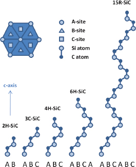
SiC is a simple 1:1 compound of two atoms that both prefer sp3 bonding. Owing to the similarity of the tetrahedral bonding, SiC has a surprisingly wide variety of polytypes. Whereas many materials are polytypic to a limited extent (e.g., α-Al2O3, γ-Al2O3), the polytypism of SiC is extensive, with over 200 polytypes having been observed.40,41,42 The basic unit is a tetrahedron of Si4C or, equivalently, C4Si; these are joined at the corners to other tetrahedra. The structure can be seen as invariant in the basal plane; the various polytypes are distinguished by the stacking sequence in the direction normal (c-axis) to the basal planes. An essentially infinite number of stacking sequences can be achieved by altering the number of layers before repeating the sequence. A number of notations have been developed; the most common notation, Ramsdell’s, labels the polytypes as nL, where n is a number indicating the periodicity in the stacking of the tetrahedra layers along the c-axis and L is a letter indicating the general crystal symmetry. For example, 3C is indicative of cubic symmetry with a three-layer repeat. This is in fact the only cubic polytype for SiC and is designated as β-SiC. The most common polytypes—2H, 4H, and 6H—all have hexagonal symmetry. There is one common rhombohedral polytype, 15R, and countless other less common and more exotic combinations like 33R or 1,200R. All of the noncubic polytypes, although different, are grouped together and considered as α-SiC. Five common polytypes of SiC are shown in Figure 5-5.
While it is often simple to qualitatively discern the presence of a particular polytype in an x-ray diffraction pattern by finding certain characteristic peaks, overlapping peaks make it not nearly as straightforward to quantitatively determine all of the polytypes present in samples. Many researchers
______________
39Ibid.
40Shaffer, P.T.B. 1969. A review of the structure of silicon carbide. Acta Crystallographica Section B: Structural Crystallography and Crystal Chemistry 25(3): 477-488.
41Mrotek, S.R. 1998. Microstructural Control of Silicon Carbide via Liquid Phase Sintering, Ph.D. Dissertation. Newark, N.J.: Rutgers University.
42Kaza, A. 2006. Effect of Gas Phase Composition in Pores During the Initial Stages of Sintering. Ph.D. Dissertation, Newark, N.J.: Rutgers University.
measure only the α and β contents of their powder and often fail to be any more specific about the relative amounts of 2H, 4H, 6H, and others because considerable effort would be required. During densification at high temperature, a given polytype can transform into a more stable one, and this can be accompanied by desirable or undesirable grain growth, along with changes in porosity, which influence various properties and ballistic performance.43,44,45,46 For example, it is common to improve the fracture toughness of SiC by exploiting the anisotropic grain growth that occurs when polytypes transform. The high sintering temperatures required for densifying SiC promote the transformation of β grains to α grains, which can become large, elongated platelet grains. By purposefully seeding an α-SiC powder with β grains before sintering, microstructures with improved fracture toughness can be designed by taking advantage of the increased crack paths around the elongated α grains. In other cases, the large α grains can act as detrimental flaws and decrease other mechanical properties.47,48
Impurities and intentional additives to SiC play an important role in the development and transformation of polytypes. As far back as 1948, Lundqvist49 had observed that different polytypes were often associated with SiC crystals of varying colors in certain powders: 6H were green, 15R were yellow, and 4H grains or samples with mixtures of polytypes appeared black. Through careful x-ray examination of over 200 powders from a variety of locations, accompanied by spectrochemical analysis, large variations in aluminum content and smaller variations in iron content were observed. At very low Al contents, the 6H polytype appeared to be favored, whereas 0.05-0.06 wt percent Al promoted the formation of 15R, with a transition to 4H above 0.10 wt percent Al. Lundqvist also observed inclusions in the grains, most of which were unreacted graphite, noting few inclusions in the clearest to light green samples. In the darker and black samples, large inclusions, found to be compounds of aluminum and iron, were often present along with changes in the nearby crystal structure. In present practice, a wide range of other impurity elements and sintering-aid additions also exert considerable influence over the temperature at which the polytype transformations occur and the exact sequence of the transformations.50,51,52,53,54
As mentioned, densifying SiC at temperatures above 1900°C will cause any β grains to transform into various α polytypes, accompanied by rapid anisotropic grain growth.55 However, if the initial material is instead an α powder, sintering at or above 1900°C will result in a fine, equiaxed α microstructure. Careful control over powder purity, sintering aids,
______________
43Shaffer, P.T.B. 1969. A review of the structure of silicon carbide. Acta Crystallographica Section B: Structural Crystallography and Crystal Chemistry 25(3): 477-488.
44Pezoldt, J. 1995. Are polytype transitions possible during boron diffusion? Materials Science and Engineering B 29(1-3): 99-104.
45Jepps, N.W., and T.F. Page. 1981. The 6H→ 3C reverse transformation in silicon carbide compacts. Journal of the American Ceramic Society 64(12): C-177-178.
46Irmscher, K., M. Albrecht, M. Rossberg, H.-J. Rost, D. Siche, and G. Wagner. 2006. Formation and properties of stacking faults in nitrogen-doped 4H-SiC. Physica B:Condensed Matter: 338-341.
47Zhan, G.D., M. Mitomo, H. Tanaka, and Y.-W. Kim. 2000. Effect of annealing conditions on microstructural development and phase transformation in silicon carbide. Journal of the American Ceramic Society 83(6): 1369-1374.
48Zhan, G.-D., R.-J. Xie, M. Mitomo, Y.-K. Kim, and N.P. Padture. 2001. Effect of beta-to-alpha phase transformation on the microstructural development and mechanical properties of fine-grained silicon carbide ceramics. Journal of the American Ceramic Society 84(5): 945-950.
49Lundqvist, D. 1948. On the Crystal Structure of Silicon Carbide and Its Content of Impurities. Acta Chemica Scandinavica 2: 177-191.
50Rixecker, G., K. Biswas, A. Rosinus, S. Sharma, I. Wiedmann, and F. Aldinger. 2002. Fracture properties of SiC ceramics with oxynitride additives. Journal of the European Ceramic Society 22(14-15): 2669-2675.
51Biswas, K., G. Rixecker, and F. Aldinger. 2003. Improved high temperature properties of SiC-ceramics sintered with Lu2O3-containing additives. Journal of the European Ceramic Society 23(7): 1099-1104.
52Kim, J., A. Rosenflanz, and I.W. Chen. 2000. Microstructure control of in-situ-toughenedα-SiAlON ceramics. Journal of the American Ceramic Society 83(7): 1819-1821.
53Kim, Y.-W., Y.-S. Chun, T. Nishimura, M. Mitomo, and Y.-H. Lee. 2007. High-temperature strength of silicon carbide ceramics sintered with rare-earth oxide and aluminum nitride. Acta Materialia 55(2): 727-736.
54Kim, W., Y.-W. Kim, and D.-H. Cho. 1998. Texture and fracture toughness anisotropy in silicon carbide. Journal of the American Ceramic Society 81(6): 1669-1672.
55Pezoldt, J. 1995. Are polytype transitions possible during boron diffusion? Materials Science and Engineering B 29(1-3): 99-104.
and processing is clearly required in order to systematically modify the microstructure and polytypes in silicon carbide.
Stacking Faults
In addition to the various long repeat sequences that constitute a particular polytype, a localized change in stacking sequence within any specific grain is a type of stacking fault. For example, a specific grain of 6H could contain local regions where the stacking sequence has changed to 4H for a few layers and then back to 6H. An understanding of stacking faults and their connection with plastic deformation behavior has come about in the study of metals over many years. The process of slip on a close-packed plane can produce the same shift in stacking sequence for a number of layers in a crystal; this shifted region is known as a deformation stacking fault but is structurally identical to a growth stacking fault.
The stacking fault can be described as an extended dislocation that is bounded by two partial dislocations. Like all imperfections, the stacking fault has an energy associated with its creation that can differ greatly between materials. Materials with low stacking-fault energy readily form many stacking faults and have large separations between the bounding partial dislocations. Materials with high stacking-fault energy require more energy for their creation and therefore form fewer and narrower, smaller faults. Silicon carbide has low stacking-fault energy, and it is not uncommon to find many growth stacking faults present throughout the crystals. Fragments from ballistic impact experiments do indeed show a considerable amount of stacking faults and twins,56,57 suggesting that materials with low stacking-fault energy twin readily under shock loading also, because the presence of large numbers of stacking faults provides locations at which twins form easily.58
There are a very large number of crystal structures for SiC differing by the stacking sequence of tetrahedral Si4C or C4Si units, and the identification and characterization of the polytypes is laborious. The phase content depends on variations in chemical impurities and sample process history.
Because well-defined SiC single crystals are available from the electronics industry, an improved understanding of the deformation of a particular polytype can be conducted. Additionally, the effect of the amount of each polytype and its spatial and size distribution within model polycrystalline materials merits investigation, especially the effect on high-rate behavior. Reducing the activation energy for stacking fault glide by purposeful alloying may provide an opportunity to enhance plasticity and energy absorption.
Availability of Ceramic Powders
Synthesis and processing of armor ceramics begins with ceramic powders, which are compacted and processed using a variety of techniques. The important issue of powder availability is discussed in this subsection. Appendix D further characterizes the current understanding of powder production for the protection materials of interest, including SiC, B4C, Al2O3, AlN, AlON, and spinel, and suggests opportunities to improve the situation.
It is difficult, if not impossible, to fabricate high-quality ceramic components without having control of the powders comprising them. The U.S.-based companies that supply many strategic ceramic components have seen a loss of domestic powder suppliers over the past two decades. Moreover, many critical armor systems rely on unique, highly specified powders for the hard ceramics. Applications ranging from armor for personnel or vehicles to high-intensity mirrors to missile radomes to rocket nozzles rely on powders coming from India, China, and Russia.
There is no powder manufacturer in the United States capable of producing the armor-grade ceramic powders needed by armor manufacturers. Nearly all oxide and carbide powders on the market have been engineered to satisfy the requirements of applications other than armor. As a consequence, ceramic armor manufacturers and university researchers are forced to employ powders that are almost certainly not optimal for armor applications. Beyond impeding research and development generally and, particularly, the development of better protection materials, the precariousness of domestic supply poses a risk for DoD should a need arise for surge production of ceramic armor materials.
The consequence of this eroded domestic supply base has been the inability of component manufacturers to design powders for a specific application. Instead, domestic producers sort or modify highly variable commodity powders of non-U.S. origin to impart the requisite “uniqueness” for an application. This is a problem for a host of powders:those for opaque armor (SiC, B4C, AlN) and those for transparent armor (MgO-Al2O3[spinel] and AlON). In many cases, lower cost, less highly specified end uses, such as abrasive grain, have given rise to a proliferation of new powder suppliers in the emerging nations. In most cases, the foreign supply chain links many small powder producers with a handful of brokers, virtually eliminating the production of tailored powders and lowering quality.
Furnace reactors were once large-scale operations; now, small producers can introduce highly variable product into a distribution stream. Precursor raw materials are also a problem. For example, for silicon carbide and boron carbide, carbon used to be obtained from high-grade, petroleum-derived coke. However, in China it is not uncommon to
______________
56Shih, C.J., M.A. Meyers, V.F. Nesterenko, and S.J. Chen. 2000. Damage evolution in dynamic deformation of silicon carbide. Acta Materialia 48(9): 2399-2420.
57Chen, M.W., J.W. McCauley, D.P. Dandekar, and N.K. Bourne. 2006. Dynamic plasticity and failure of high-purity alumina under shock loading. Nature Materials 5(8): 614–618.
58Murr, L.E. 1987. Metallurgical effects of shock and high-strain-rate loading. Pp. 1-45 in Materials at High Strain Rates. T.Z. Blazynski, ed. New York, N.Y.: Elsevier Science.
see anthracite coal or low-purity petroleum coke used. The consequence is an end product whose chemistry is highly variable. Component suppliers are now faced with how to make a consistent product meeting today’s armor specifications. Improving ceramic performance can no longer entail simply changing the initial powder since the production and supply of powders are no longer within domestic control.
By losing control of powder processing, U.S. armor makers have reached a point at which variability in powders is expected, tolerated, and, in many cases, ignored. While processing treatments have been developed to improve the overall uniformity of powders, this results in dense components whose microscale variability reflects the intrinsic variability of the parent powder. From a simple business or logistical point of view, manufacturers can no longer assure that the powders used in highly specified components will meet strict testing requirements.
The Defense Production Act Title III program gives DoD special authority to issue purchase commitments, loan guarantees, capital investment, or research and development investment to provide an assured domestic supply for critical materials. The business case analysis to support a Title III program in ceramic armor materials is beyond the scope of this study. The committee recommends DoD undertake such an analysis to determine whether domestic production of ceramic armor precursor materials would be a good candidate for Title III.
Finding 5-2a. The goal for future armor systems is not only to maintain current performance but to dramatically increase it as well. As such, it is critical that the United States regain and maintain control of the armor raw material supply chain. There is a need for a strategic powder production infrastructure within the United States to bring about the next generation of opaque and transparent armors. This will not only permit a consistent and reliable supply but also allow for the design of powders whose intrinsic properties are optimized for armor applications.
Finding 5-2b. Powder processing affects the intrinsic properties of many armor ceramics. There is little work on how the powders can be designed and manipulated at the atomic, nano, and micro levels in ways to maximize their potential as raw armor materials.
Finding 5-2c. There are no powders produced specifically for armor applications. The oxide and carbide powders that are commercially available have been designed for other applications. Most powder processes are energy-intensive processes with large carbon emission footprints, and U.S. environmental regulation costs have reduced the competiveness of U.S. producers, with foreign powder producers benefiting from low-cost but environmentally questionable operations. There is no domestic feedback on powder characterization to assist ceramic producers in researching or producing new prototype powders.
Finding 5-2d. Although the availability of high-quality ceramic powders for protection materials is critical to national defense, there is currently no domestic source of ceramic powders to meet DoD needs.
PROCESSING AND FABRICATION TECHNIQUES FOR ARMOR CERAMICS
A variety of fabrication techniques have been employed in the processing of armor ceramic materials. There are two broad classes of forming operations: (1) cold methods—slip casting, extrusion, and die pressing—and (2) high-temperature pressureless and pressure-assisted sintering methods—hot pressing, hot isostatic pressing, and spark plasma sintering (see Box 5-1).
Since armor materials are mostly strongly covalently bonded solids, high-temperature densification, often with pressure-assisted techniques, is required. The goal of densification is to optimize bonding and eliminate porosity in the compacted powder so that full theoretical densities, along with homogeneous microstructures, can be achieved in the final sintered materials. Near-net-shape fabrication that minimizes machining and finishing operations is also desired for cost savings.
The starting point in ceramic forming is the compaction of powders. Die pressing is the predominant forming method for symmetrical shapes such as hexagonal and square tiles. High-pressure compaction methods can be divided into
BOX 5-1
Processing of Ceramic Powders
Hot-pressed SiC and B4C powders yield uniform full-density products with homogeneous microstructures and good ballistic performance. Near-net-shape ceramic processing is of great interest, although powders with additives and sintering aids compacted by means of lower cost conventional pressing methods into “green,” or unfired, form and then pressureless-sintered (that is, at atmospheric pressure) yield materials with nonuniform density distribution and microstructure. Their ballistic performance is inferior for higher threat levels compared to that of hot-pressed material.
static and dynamic techniques.59 With static compaction, a constant pressure is applied onto a sample for a certain period of time, typically a few seconds. Dynamic compaction uses a pressure pulse with a pulse duration of less than a few milliseconds, resulting in a pressure wave that travels through the sample. In both static and dynamic compaction the pressure can be applied in a uniaxial, biaxial, radial, or isostatic/isodynamic mode.
The choice of a process for compacting powders for the fabrication of ceramics depends on the complexity of the shape of the ceramic part.60 The most widely used forming method for armor production is uniaxial die pressing, whereby uniaxial pressure is applied to the powder placed in a die between two rigid punches. Binder and/or lubricants are added to the powders to reduce the friction and facilitate extracting the formed part from the die. This formed part, often termed a “green” compact because it is unfired, is subsequently heat treated (“sintered”) to densify it.
The typical density of the parts achieved after uniaxial die pressing is 50-55 percent of the theoretical density. Density gradients occur depending on the part’s shape, aspect ratio, and size. These gradients are a likely source of voids and undesirable porosity in sintered armor tiles. Other defects in laminar character can appear oriented normal to the pressing axis. After die pressing, the part will have shrunk by 20 to 40 percent or so, and the final part dimensions are achieved by machining and grinding.
Uniaxial die pressing is widely used for the low-cost mass production of simple parts. In certain cases, cold isostatic pressing (CIP) is used to further increase the density (up to 73 percent) after die compaction. CIP is conducted as wet bag isostatic pressing in pressure vessels, and parts can be produced as large as a few meters in height and a meter or more in diameter, with large parts having substantially higher costs. Hydrostatic pressures of 100-700 MPa can be achieved with suitable CIP systems.61
Dynamic compaction approaches are potential alternatives for making near-net-shape parts with very high “green” densities (up to 95-100 percent). Dynamic compaction depends on the way the pressure waves needed to densify the sample are generated and how the reflected waves are absorbed. One of the best-known methods is compaction using explosives. However, this method would be problematic as an industrial manufacturing process in a factory environment. The alternative dynamic magnetic compaction (DMC) technique uses magnetic pulse pressures and is suitable for a factory environment. The DMC rapid consolidation technique developed by IAP Research, Inc., is based on a magnetic pulse that launches a pressure wave that travels at 100-300 m/s through the powders, giving rise to stress gradients; the technique is designed so as to absorb reflected waves.62 The stress gradients cause particle motion, particle deformation, and particle fracture, especially in brittle powder materials at high pressure; accordingly, they bring about a higher degree of consolidation than static pressing.63 Very high green densities of the compacts can be realized—in fact, they approach theoretical densities even before sintering. Because DMC samples have higher compact densities they can be sintered at lower temperatures or for shorter periods of time to obtain close-to-full-density materials. The dynamically pressed samples exhibit rather homogeneous microstructures after pressureless sintering and properties similar to those of hot-pressed material. In addition, dynamic processing techniques allow retention of special powder microstructures (including nano grain size) after sintering owing to the short sintering time and lower sintering temperatures. In light of its advantages, dynamic compaction needs to be seriously investigated for armor production methods.
Appendix E characterizes commonly used ceramic sintering processes and discusses issues surrounding their application to opaque armor materials. The advantages and disadvantages of these processes are summarized in Table 5-1.
The effect of specially designed powder microstructures, such as nano grain sizes, on the controlled fracture to enhance ballistic performance is being investigated by the Army Research Laboratory (ARL) and other laboratories. Ceramic manufacturers are also exploring ways to improve performance through modifications to the front surface of a ceramic armor plate—in one case by molding multiple nodes with conical or rounded shapes. By modifying the impact angle of the projectile, the ballistic performance of ceramics could be improved. Ceramic nodes, spheres, or hollow ceramic spheres give the structure a multiplicity of surfaces for a multiplicity of crack initiation sites.64 These nodes cause part of the energy of the projectile to initiate a multiplicity of cracks at the node surface; however, spherical nodes arrest cracks. Other candidates for exploring the improvement of performance include novel alloying and doping methods.
______________
59Jak, Michiel J.G. 2004. Dynamic compaction of nano-structured ceramics. Nanocomposites. Volume 10 in Electronics Materials Science & Technology. Springer.
60Tressler, R.E. 2004. An assessment of low cost manufacturing technology for advanced structural ceramics and its impact on ceramic armor. Pp. 451-462 in Progress in Ceramic Armor. New York, N.Y.: John Wiley & Sons.
61Nishimura, T., K. Jinbo, Y. Matsuo, and S. Kimura. 1990. Forming of ceramic powders by cyclic-CIP: Effect of bias pressure. Journal of the Ceramic Society of Japan 98(7):735-738.
62Chelluri, B., E. Knoth, E. Schumacher, and L.P. Franks. 2010. Method for Producing SiC armor tiles of higher performance at lower cost. Pp. 199-205 in Advances in Ceramic Armor VI: Ceramic Engineering and Science Proceedings, Volume 31, Issue 5. J.J. Swab, ed. Hoboken, N.J.: John Wiley & Sons.
63National Research Council. 1983. Dynamic Compaction of Metal and Ceramic Powders. Washington, D.C.: National Academy Press.
64Medvedovski, E. 2010. Ballistic performance of armor ceramics: Influence of design and structure. Part 2. Ceramics International 36(7): 2117-2127.
TABLE 5-1 Manufacturing Processes for Opaque Ceramic Armor Materials
|
|
|||
|
Process |
Material |
Advantages |
Disadvantages |
|
|
|||
|
Hot pressing |
Ceralloy B4C Norbide B4C Ceralloy SiC, SiC–N, TiB2 |
Lower temperature, lowest porosity |
Shape limitation |
|
Solid-state sintering (SSS) or pressureless sintering |
Hexoloy SiC Purbide SiC (MCT/SSS) SiC |
No grain boundary phase, low porosity |
Higher temperature, grain coarsening |
|
Liquid-phase sintering (LPS) |
Ekasic-T (MCT LPS) SiC |
Lower temperature, fine grains, low porosity |
Oxide grain boundary phase |
|
Reaction bonding |
Si/SiC, Si/B4C (MCT/RBSC, RBBC) |
Low temperature, excellent complex shape capability |
Residual silicon |
|
|
|||
NOTE: MCT, M Cubed Technologies, Inc., RBBC, reaction-bonded boron carbide; RBSC, reaction-bonded SiC.
SOURCE: Karandikar, P.G., G. Evans, S. Wong, M.K. Aghajanian, and M. Sennett. 2009. A Review of Ceramics for Armor Applications. Ceramic Engineering and Science Proceedings 29(6): 163-175.
Finding 5-3. Refractory ceramics such as SiC and B4C require very high sintering temperatures (>2150°C-2200°C) for long periods (more than 2 hours of dwell time) and the use of sintering aids to obtain full density by solid-state sintering or liquid-phase sintering. Neither are the hot pressing or the high-temperature, pressureless sintering methods satisfactory for processing powders with special microstructures (including nano grain sizes) because they induce grain growth. Fast, high-density compaction techniques, coupled with low-temperature sintering methods (including spark plasma sintering), are therefore needed to permit the retention of specially designed initial powder microstructures.
Infrared domes, lenses, reconnaissance windows, and windows on military vehicles must be transparent to radiation of certain wavelengths and must also resist damage from airborne debris and penetration from projectiles. They should retain a degree of transparency after a hit and should withstand multiple hits.
Glass is the traditional window material. Glass windows can be produced in large sizes by the relatively inexpensive float glass process. Most windows consist of multiple layers of glass, usually made of soda lime or borosilicate, adhesively bonded to one another and backed by a polycarbonate layer. Care is taken to avoid flaws on the layer surfaces. Glasses can be toughened with thermal or chemical treatments that induce compressive stresses on their surfaces.
Laminated glass windows can resist penetration by certain threats, but at an areal density of 50 to 55 lb/ft2 they impose a severe weight penalty. Current Humvee windows are about 4 in. thick and weigh about 90 lb each. The six windows on a typical vehicle thus weigh as much as several soldiers. Window weight contributes to worn-out transmissions and suspension systems, which in turn cause military vehicles to be taken out of service for repair. This underlines the motivation to innovate lighter-weight window materials and window structures.
Glass ceramics are glass-based materials in which a dense population of ceramic nanocrystallites is embedded in the amorphous silica matrix (Figure 5-6). These materials were originally developed as zero-coefficient-of-expansion materials for use in cook tops and fireplace screen windows. Because they were found to have ballistic performance tens of percent better than the baseline glasses, these glass ceramics are beginning to replace traditional window glass on military vehicles. Many chemistries and processing routes have been explored to achieve glass ceramics with even better ballistic performance while maintaining transparency (nanocrystallite size must be kept at less than ~0.1 × the wavelength of light). Laminated glass ceramic windows are currently being installed in military vehicles.
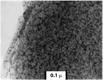
FIGURE 5-6 Scanning TEM micrograph of the microstructure of spinel glass ceramic. Shown is the uniform dispersion of the dark 10-20 nm spinel crystals throughout the lighter continuous, highly siliceous glass matrix. SOURCE: Pinckney, L.R., and G.H. Beall. 2008. Microstructural evolution in some silicate glass-ceramics: A review. Journal of the American Ceramic Society 91(3): 773-779.
TRANSPARENT CRYSTALLINE CERAMICS
Three candidates for transparent armor—aluminum oxynitride (AlNx·(Al2O3)1-x), known as AlON; spinel (MgAl2O4); and sapphire (Al2O3)—are harder, stronger, and tougher than soda lime and borosilicate glass, and they have been shown to provide protection against armor-piercing rounds at roughly half the weight and thickness of conventional glass laminates. However, the materials are quite expensive compared to glass and they are not available in large quantities. Their high cost and low production volume prevent their widespread use in armor material and currently limit their application to strike-face materials.
AlON is a polycrystalline, large-grained (200 μ) ceramic material formed from a solid solution of Al2O3 and AlN. This solution is stable over a wide range of mixture ratios centered at 9Al2O3–5AlN (35.7 mol percent AlN), has the chemical formula Al23O27N5, and exhibits an ambient density of 3.67 g/cm3. Because of its cubic crystalline structure, AlON is optically isotropic and therefore transparent, even in polycrystalline form. Conventional powder processing techniques have been used to produce large (17× 34-in.) plates of high optical quality. A tiling approach to the production of larger transparent armor windows using AlON tiles with dimensions between 12 × 12 in. and 14 × 20 in. is in development.65,66,67
Producing a nanocrystalline transparent ceramic may offer improved mechanical behavior. Several nontransition metal oxides and oxynitrides, including Al2O3 and AlON, can be produced as nanocrystalline ceramics. If the ceramic is transparent as a micron-scale polycrystal or single crystal, it will maintain that transparency when it is produced in the nanocrystalline form, provided there is no porosity at the 0.5 μ scale and above. However, B4C, SiC, and Si3N4 often contain carbon impurities, which can lead to loss of transparency.
Spinel is a stoichiometric compound of magnesium and aluminum oxides, MgAl2O4. Fine-grained (micron or submicron grains) spinel has high transparency and hardness and good ballistic resistance (Figure 5-7). Exceptionally fine-grained material (grain size as small as 0.6 μ) can be obtained by hot pressing and subsequent heat treatments. Novel processing methods, such as spark plasma sintering, are also being investigated to achieve high mechanical strength and hardness without sacrificing optical transparency. Prototype 11- × 14-in. armor windows have been successfully fabricated and delivered to the Army. Larger mosaic windows with minimum detectability of the seam have also been produced.68,69
Sapphire is a single-crystal alumina (Al2O3). Although sapphire has a density nearly double that of conventional window glass, its superior performance allows equivalent ballistic protection at a reduction in system weight and thickness of about 40 percent. Saint-Gobain Crystals, the sole supplier of integrated ceramic transparent armor in the world, currently produces plates up to 9 × 26 in. and 12 × 24 in.70,71,72Since sapphire is grown from the melt in individual crystal growers, plates are produced one by one and are expensive. Smaller plates, which are less expensive to produce, can be seamed together to achieve larger windows.
Finding 5-4a. Transparent crystalline ceramics are harder, stronger, and tougher than glasses and glass ceramics and have much better penetration resistance. Transparent ceramics could most likely meet the Army’s requirements for lightweight protective windows. However, they are expensive and are not available in the quantities and sizes needed to replace existing vehicle windows. The cost of transparent ceramics might be reduced by identifying less expensive sources of powders; improving powder processing procedures, fabrication, and finishing; increasing the production volume by identifying and developing secondary markets; and advancing seaming technologies that enable large windows to be produced by joining smaller tiles.
Finding 5-4b. It could be productive to explore transparent crystalline ceramics with different chemistries and processing methods and microstructures, including nanocrystalline ceramics, to achieve control over fracture and fragmentation behavior while maintaining transparency.
Finding 5-4c. Composite windows made of three materials—glasses, glass ceramics, and transparent crystalline ceramics—represent a viable trade-off between cost and performance. Superior laminated armor configurations made of transparent glasses, glass ceramics, crystalline ceramics, and polymers for the front (strike), back, and intermediate
______________
65McCauley, J.W., P. Patel, M. Chen, G. Glide, E. Strassburger, B. Paliwal, K.T. Ramesh, and D.P. Dandekar. 2009. AlON: A brief history of its emergence and evolution. Journal of the European Ceramic Society 29(2): 223-236.
66Goldman, L.M., R. Foti, M. Smith, U. Kashalikar, and S. Sastri. 2009. AlON transparent armor. Pp. 225-232 in Advances in Ceramic Armor V, Volume 30, Issue 5. J. Swab, ed. Hoboken, N.J.: John Wiley & Sons.
67Goldman, L.M., R. Twedt, R. Foti, M. Smith, and S.A. Sastri. 2009. Large area AlON windows for reconnaissance and armor applications. Paper 7302 06 in Window and Dome Technologies and Materials XI, Proceedings of SPIE Volume 7302. R.W. Tustison, ed. Bellingham, Wash.: Society of Photo-Optical Instrumentation Engineers.
68Krell, A., J. Klimke, and T. Hutzler. 2009. Advanced spinel and submicron Al2O3for transparent armor applications. Journal of the European Ceramic Society 29(2):275-281.
69Krell, A. 2009. Ballistic strength of opaque and transparent armor. American Ceramic Society Bulletin 86(4): 9201-9207.
70Rioux, J., C. Jones, M. Mandelartz, and V. Pluen. 2007. Transparent armor. Advanced Materials and Processes 165(10): 31-33.
71Jones, C.D., J.B. Rioux, J.W. Locher, V. Pluen, and M. Mandelartz. 2009. Ballistic performance of commercially available Saint-Gobain sapphire transparent armor composites. Pp. 113-125 in Advances in Ceramic Armor III: Ceramic and Engineering Science Proceedings, Volume 28, Issue 5. L.P. Franks, J. Salem, and D. Zhu, eds. Hoboken, N.J.: John Wiley& Sons.
72See the Saint-Gobain Crystals’s sapphire substrates Web site, http://www.photonic.saint-gobain.com/sapphire-substrates.aspx.
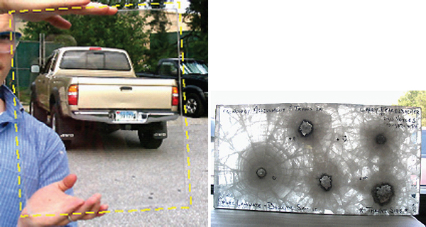
FIGURE 5-7 Photo showing the transparency (left) and multi-hit performance (right) of spinel. SOURCE: Spinel and Optical Ceramics-Armor. Undated. Available online at www.techassess.com/tech/spinel/spinel_armor.htm. Last accessed April 8, 2011.
plates should be identified by computationally simulating projectile impacts in which the number, thickness, location, order, and so forth of the plates are varied.
The field of high-performance fibers is only about 50 years old. This section briefly reviews the history of their development and current production technology and then discusses opportunities for technological innovations relevant to protection materials. Nylon and silk fibers had been used to make armor vests for soldiers, but with very limited success. Nylon was invented at DuPont and commercialized in 1939. In the 1960s, DuPont developed polyparaphenylene terephthalamide (PPTA), a much stiffer semirigid rod molecule that resulted in a liquid crystalline spinning solution and produced revolutionary structured fibers of very high crystallinity. When these fibers were woven into yarns and the yarns into a flexible multi-ply fabric, the resulting material, now known as Kevlar, was able to stop a bullet.
Typical properties of selected fibers and some high-performance fibers are given in Table 5-2; their specific strength is plotted against specific stiffness in Figure 5-8. Figure 5-9 schematically depicts the molecular structures of a typical textile fiber (e.g., polyethylene terephthalate or nylon with ~10 μ diameter or other larger diameter fibers); current high-performance polymeric fibers such as gel-spun polyethylene, with folding and entanglement, and semirigid-rod polymers like PPTA; and the ideal fiber made up of either polymer molecules or carbon nanotubes (CNT).
Commodity textile fibers contain significant amounts of amorphous-phase (50 percent) and chain-folded crystals, resulting in typical strengths of 0.5-1.0 GPa. The ability to highly orient macromolecules and to form extended chain crystals with a high degree of crystallinity creates high-performance fibers, whose strength is typically an order of magnitude larger (up to 6 GPa). Realizing that the ideal fiber structure is as shown in the right-hand panel of Figure 5-9 allows straightforward estimation of its theoretical properties based on the strength of the bonds in the chain and the cross-sectional area of the molecule.73,74,75 The predicted tensile strength of a perfect, fully extended polymeric fiber such as polyethylene is about 30 GPa and that of a perfectly packed, single-wall CNT fiber of ideal diameter should be about 150 GPa. Achieving fibers that approach the predicted theoretical strength will require the removal of any voids, foreign particles, and chain entanglements. In addition, a polymer’s molecular weight—that is, the polymer chain or CNT length—also plays a role in governing tensile strength since the number of chain end defects is inversely proportional to the molecular weight. Thus, synthetic methods that make it possible to also increase the polymer chain or CNT length will also have to be developed to narrow the gap between the current tensile strength and the theoretical limit.
Appendix F presents a brief review of high-performance fibers, including the following:
______________
73Elices, M., and J. Llorca. 2002. Fiber Fracture. Amsterdam: Elsevier.
74Dumitrica, T., M. Hua, and B.I. Yakobson. 2006. Symmetry-, time-, and temperature-dependent strength of carbon nanotubes. Proceedings of the National Academy of Sciences of the United States of America 103(16): 6105-6109.
75Kelly, A., and N.H. MacMillan. 1986. Strong Solids, third edition. Oxford, England:Clarendon Press.
TABLE 5-2 Typical Properties of Selected Fibers
|
|
|||||
|
Fiber |
Density (g/cm3) |
Modulus (GPa) |
Tensile strength (GPa) |
Compressive strength (GPa) |
Strain-to-failure (percent) |
|
|
|||||
|
Polymeric fibers |
|||||
|
Nylon 66 |
1.14 |
25 |
|||
|
Silk |
1.36 |
30-60 |
1.1-2.9 |
7-12 |
|
|
Kevlar 49 |
1.45 |
3.5a |
2.6-4.2 |
||
|
Kevlar 149 |
1.47 |
3.4a |
|||
|
Spectra 1000 |
2.4-3.4 |
0.2a |
2.8-3.0 |
||
|
Zylon HM |
1.56 |
5.8a |
0.3a |
2.5 |
|
|
M5 (PIPD) |
1.70 |
270a |
>4.0a |
>1.4 |
|
|
Vectran |
1.47 |
65a |
2.9a |
3.3 |
|
|
Carbon fibers |
|||||
|
Pitch based (P-100) |
2.15 |
2.41a |
0.3 |
||
|
Pitch based K-1100 |
2.2 |
965a |
3.10a |
||
|
PAN based (T-300) |
1.79 |
3.75a |
|||
|
PAN based (T-800) |
1.8 |
300a |
5.6a |
~3.0a |
|
|
Ceramic and glass fibers |
|||||
|
Alumina (Al2O3) |
3.7 |
1.7a |
|||
|
Boron |
2.5 |
415a |
3.5a |
5.0a |
|
|
SiC (Nicalon) |
2.8 |
200a |
2.8a |
3.1a |
|
|
SiC (CVD) |
3.0 |
400a |
3.4a |
||
|
E glass |
2.58 |
3.4a |
2 |
||
|
S glass |
2.46 |
90a |
4.5a |
||
|
Alumina borosilicate (Nextel 440) |
3.05 |
186a |
2.1a |
||
|
Steel |
7.8 |
200a |
2.8a |
1.4 |
|
|
|
|||||
NOTE: HM, high-modulus; PIPD, poly[2,6-diimidazo(4,5-b-4′,5′-e)pyridinylene-1,4(2,5-dihydroxy)phenylene]; PAN, polyacrylonitrile; CVD, chemical vapor deposition.
aLongitudinal.
bTransversal.
cShear.
SOURCE: Warner, S.B. 1995. Fiber Science. Upper Saddle River, N.J.: Prentice-Hall; Minus, M., and S. Kumar. 2005. The processing, properties, and structure of carbon. JOM 57(2): 52-59; Kozey, V.V., H. Jiang, V.R. Mehta, and S. Kumar. 1995. Compressive behavior of materials 2: High-performance fibers. Journal of Materials Research 10(4):1044-1061.
- Semirigid-rod PPTA, polybenzoxazole, and poly(pyridobisimidazole) fibers (e.g., Kevlar, Twaron, Technora, Zylon, and M5),
- Polyethylene (Spectra, Dyneema),
- Thermotropic liquid crystalline polymeric fibers (Vectran),
- Carbon fibers,76,77,78
- CNT fibers, and
- Alumina, boron, silicon carbide, glass, and alumina borosilicate ceramic fibers.79,80,81
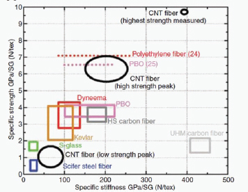
FIGURE 5-8 Strength and stiffness of the strongest fiber sample and of fibers typical of the high-strength and low-strength peaks in the 1-mm gauge length distribution versus the properties of other commercially available, high-performance fibers. Two laboratory observations of higher strengths in commercialized systems are also included (reference numbers are shown). SOURCE: Koziol, K., J. Vilatela, A. Moisaa, M. Motta, P. Cunniff, M. Sennett, and A. Windlel. 2007. High-performance carbon nanotube fiber. Science 318(5858): 1892-1895.
______________
76Donnet, J.-B., T.K., Wang, S. Rebouillat, and J.C.M. Peng, editors. 1998. Carbon Fibers, third edition. New York, N.Y.: Marcel Dekker.
77Peebles, L.H.. 1995. Carbon Fibers: Formation, Structure, and Properties. Boca Raton, Fla.: CRC Press.
78Minus, M., S. Kumar. 2005. The processing, properties, and structure of carbon. JOM 57(2): 52-59.
79Elices, M., and J. Llorca. 2002. Fiber Fracture. Oxford, England: Elsevier Science, Ltd.
80Chawla, K.K. 1998. Fibrous Materials. Cambridge, England: Cambridge University Press.
81Watt, W.W., and B.V. Perov. 1985. Strong Fibers. Amsterdam: Elsevier Science Publishers.
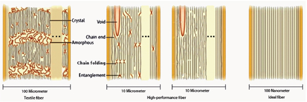
FIGURE 5-9 Schematic of transverse sections of fibers. Textile fibers are large diameter (~100 μ) with a partial crystalline structure (left); high-performance fibers are around 10 μ in diameter and feature more extended chains, leading to higher strength and modulus, but still contain many defects (center), whereas the ideal fiber would have a much smaller diameter (~100 nm) and be essentially defect free (right). SOURCE:Modified from Chae, H.G., and S. Kumar. 2008. Materials science: Making strong fibers. Science 319(5865): 908-909. Reprinted with permission from AAAS.
Effect of Fiber Diameter on Strength in High-Performance Fibers
Fiber tensile strength increases with decreasing fiber diameter. This has been demonstrated for polymeric fibers, carbon fibers, and ceramic and glass fibers. The current commercial carbon fibers range in diameter from 4 μ to 10 μ; for polymeric and most ceramic and glass fibers, diameters are in the range of 10 μ to 15 μ. Fibers processed by chemical vapor deposition, such as boron fibers, tend to have much larger diameters, typically 100-150 μ. The probability of finding defects decreases with decreasing fiber diameter. Developing new processing technologies for the economical production of smaller diameter fibers (1 μ or less) that also provides good control of fiber drawability is expected to significantly improve fiber tensile strength. Additionally, processing to achieve hollow fibers with a relatively thin wall (less than 1 μ) may reduce tensile strength just as it reduces the overall fiber diameter. Processing techniques for this new fiber class are actively under investigation.
Relating Tensile Properties to Ballistic Performance
The development of a new fiber material and a process to manufacture it typically costs several hundred million dollars. This presents a very high barrier for new materials and new process entry in the marketplace. It would be beneficial to be able to forecast ballistic performance from simple fiber tensile strength data obtainable from spinning small amounts of fiber. Further development of the Cuniff equation/model could be a step in that direction. Rigorous testing, evaluation, and refinement of this and other fiber ballistic models82 could allow predicting fabric ballistic performance at a much earlier stage.
Finding 5-5. Rigorous testing, evaluation, and refinement of fiber ballistic models could allow predicting fabric ballistic performance at a much earlier stage.
Approaching the Theoretical Tensile Strength and Theoretical Tensile Modulus
Between 75 and 90 percent of the theoretical fiber modulus can now be achieved in some commercially produced fibers. This has been demonstrated in carbon fiber (K-1100), in Kevlar 149, and in SiC fiber processed by the chemical vapor deposition method. However, the situation for the theoretical tensile strength of most commercial fibers is quite different: Current best fibers still exhibit 10 percent or so less strength than their theoretical strengths. For example, the theoretical tensile strength of polyethylene fiber is predicted to be 33 GPa,83 and that of carbon fibers, including CNT fibers, is predicted to be between 100 and 150 GPa.84,85 The tensile strength of polymeric fibers is limited by the presence of chain ends, chain entanglements, chain misorientation, voids, and impurities.86 Similarly, various types of defects limit the tensile strength of carbon and
______________
82Phoenix, S.L., and P.K. Porwal. 2003. A new membrane model for the ballistic impact response and V50 performance of multi-ply fibrous systems. International Journal of Solids and Structures 40(24): 6723-6765.
83Elices, M., and J. Llorca. 2002. Fiber Fracture. Oxford, England: Elsevier Science.
84Dumitrica, T., M. Hua, and B.I. Yakobson. 2006. Symmetry-, time-, and temperature-dependent strength of carbon nanotubes. Proceedings of the National Academy of Sciences of the United States of America 103(16): 6105-6109.
85Kelly, A., and N.H. MacMillan. 1986. Strong Solids, third edition. Oxford, England:Clarendon Press.
86Chae, H.G., and S. Kumar. 2008. Materials science: Making strong fibers. Science 319(5865): 908-909.
ceramic fibers. Eliminating these defects has the potential to improve both the strength and the strain-to-failure and, potentially, the ballistic performance, by a factor of as much as 10 to 50. Achieving such strength would require making a perfectly oriented extended polymer chain or nanotube fiber free of any type of defect (last section in Figure 5-9).
Is the goal of making a near perfect and continuous fiber achievable? Arguably the highest perfection in materials processing has so far been achieved by the microelectronics industry. The electronic devices made for communication, data storage, and data processing contain materials with near perfection at the nanometer scale. This material perfection can be repeated not in just a few devices but in devices that are mass produced and perform with a high degree of reliability. If the investment in the field of high-performance fibers was at even a small fraction of the investment in the microelectronics industry, it might be possible to achieve fibers approaching a nearly ideal structure and to thus attain theoretical strength values. Continued developments in nanotechnology, both the characterization and processing tools, will help in the production of enhanced fibers. For example, a gel-drawn polyethylene nanofiber was recently reported by Massachusetts Institute of Technology scientists to have an axial thermal conductivity value exceeding 100 W/m/K.87 This makes polyethylene, normally considered a thermal insulator, into a thermal conductor, with an axial thermal conductivity exceeding that of a number of metals. This extraordinary thermal conductivity is a result of the near-perfect extended chains in this experimental polyethylene fiber that has not yet been achieved in commercial polyethylene fibers such as Spectra and Dyneema.
The Need for Mechanical Tests at High Strain Rates
The tensile properties of elastic fibers such as Kevlar and carbon exhibit very low or no strain-rate dependence, while fibers that have some viscoelastic behavior, such as current high-performance polyethylene fibers (Spectra and Dyneema), exhibit a relatively high degree of strain-rate dependence due to the many rate-dependent dissipative processes. In general, as the structural perfection of the fibers improves, there should be a decrease in the strain-rate sensitivity. The data in Table 5-2 are generally from quasi-static tests; however, a great need exists for mechanical property tests on fibers at high strain rates (greater than 10,000/s) for assessing their true potential as ballistic materials.
Fundamental questions abound: What is the optimum tow size—that is, the number of filaments—for the fiber assembly for a given application? Are there systems in which having individual filaments in a given layer, resulting in a layer that is about as thick as the fiber diameter, would be preferable to a yarn layer, or fabrics that are thousands of filaments thick? What is the effect of factors such as interfiber friction in a one-dimensional fiber assembly like yarn; a two-dimensional fiber assembly, such as a woven fabric; and other systems in which fibers are used?
Similarly, the role of interphase and interface properties in fiber/matrix systems needs to be understood. In this context it should be noted that the effect of fiber friction on fiber assemblies has historically been studied and understood at relatively low and moderate strain rates. Likewise, the role of interfaces and interphases has been characterized and studied at low to moderate strain rates.
On the basis of predicted strain-to-failure,88 ideal CNT fibers—that is, with no defects or entanglements—will have a specific tensile strength of 70 N/tex,89 for a single-wall CNT fiber with a CNT diameter of 2 nm, this equates to a tensile strength of 70 GPa.90
Finding 5-6a. Near-term opportunities (5 to 15 years) are very promising, especially for achieving advances in fiber strength that would allow tensile strengths to reach 8 to 15 GPa from the present 6 GPa. Even without a change in modulus, a twofold increase in strength increases the work-to-fracture by a factor of four owing to the improved mechanical behavior of small-diameter fibers that result from enhanced crystal perfection and orientation. Specific materials with good potential for further development include the following:
- Ultrahigh-molecular-weight polyethylene (UHMWPE) fiber. Polyethylene fiber with a tensile strength of 7 GPa has been reported in the laboratory.91
- Glass fiber. Glass fibers with a tensile strength of >10 GPa have recently been reported by Corning.92
- Novel carbon fibers. Combining gel spinning and incorporating CNTs having smaller diameters than the current state-of-the-art fibers may align the polymer chains surrounding the CNTs during processing.93,94
______________
87Shen, S., A. Henry, J. Tong, R. Zheng, and G. Chen. 2010. Polyethylene nanofibres with very high thermal conductivities. Nature Nanotechnology 5(4): 251-255.
88See Dumitrica, T., M. Hua, and B.I. Yakobson. 2006. Symmetry-, time-, and temperature-dependent strength of carbon nanotubes. Proceedings of the National Academy of Sciences of the United States of America 103(16): 6105-6109.
89“Tex” is the mass of a 1,000-meter length of fiber in grams.
90Chae, H.G., and S. Kumar. 2008. Materials science: Making strong fibers. Science 319(5865): 908-909.
91Judah M. Goldwasser, Program Manager, Defense Advanced Research Projects Agency,“DARPA’s role in armor,” presentation to the committee on June 8, 2010.
92J. Jay Zhang, Program Manager, Dow Corning, presentation to the committee on June 8, 2010.
93Chae, H.G., Y.H. Choi, M.L. Minus, and S. Kumar. 2009. Carbon nanotube reinforced small diameter polyacrylonitrile based carbon fiber. Composites Science and Technology 69(3-4): 406-413.
94Chae, H.G., M.L. Minus, A. Rasheed, and S. Kumar. 2007. Stabilization and carbonization of gel spun polyacrylonitrile/single wall carbon nanotube composite fibers. Polymer 48(13): 3781-3789.
Postprocessing tensioned heat treatment could lead to a novel composite graphitic carbon fiber.
- CNT fiber. Pure CNT fibers with a tensile strength of ~10 GPa have been made in the laboratory. Nano graphene ribbon may also be useful for producing fibers with high tensile strength and high tensile modulus.
- Poly(pyridobisimidazole) fiber. Based on early laboratory developments, M5 fiber may have potential as a new ballistic fiber.
Finding 5-6b. Longer-term opportunities (25+ years) point to continued improvements in fiber strength. The theoretical strengths of polymeric, carbon, and ceramic fibers are 30 to 150 GPa.95,96,97 Advances in nanotechnology—in both characterization and processing tools—will aid in the production of fibers that approach theoretical tensile strength values, which will, in turn, have a strong impact on weight savings for body armor.
Finding 5-6c. A better understanding of the role of fiber friction in fiber assemblies and of the interface and interphase in composites and in nanocomposites at high strain rates (typically greater than 104 per second) is needed to predict their ballistic performance.
The ability to create fabrics from fibers by weaving affords the creation of low-density materials that can withstand both ballistic and blast events. Most ballistic fabrics have two-dimensional plain weave yarns in two orthogonal directions, although some work is being done on three-dimensional weaves and on nonwoven fabrics. Organic polymers or inorganic glass or ceramic fibers have the requisite high stiffness and high-strength-to-weight ratios to produce lightweight high-performance fabrics. Leading organic fibers were discussed previously. Alumina (Nextel) fibers are an important ceramic fiber. Nextel and Kevlar fabrics are used for shielding against hypervelocity impacts such as meteorites in the International Space Station.98 Fabrics are also used for blast containment—Kevlar fabrics, for example, have been developed for blastproof cargo containers for airplanes.99Many factors affect the response of fabrics to ballistic impact. These include material properties of the fiber, the yarn, the weave architecture, the far-field boundary conditions, interyarn friction, friction between the projectile and the yarn, and projectile geometry and velocity.
Ballistic Testing and Experimental Work on Fabrics
For typical ballistic testing, fabric samples are clamped on the warp yarns and the incoming projectile is caught by the yarn network. Kinetic energy is transferred to the fabric as the stress wave spreads outward from the point of impact. The energy is partially dissipated by fiber deformation and interfiber friction caused by interfiber slippage. A projectile with sufficiently high mass and velocity may penetrate the fabric and cause it to fail.
Inspection of the impact area can help in understanding the failure mechanism of fibers under ballistic impact; however, such postfailure analysis provides little information on other energy dissipation paths. For insight into the dynamics of the material’s response to ballistic impact, Wilde et al.100 observed a single layer of nylon fabric by high-speed photography and found that the majority of the energy was absorbed by breaking of the orthogonal yarns. Starratt et al.101 designed a simple and cost-effective system for continuously measuring ballistic impact. They used an enhanced laser velocity system to monitor the continuous motion of the projectile and thus determine the impact force and energy loss. Schmidt et al.102 proposed an advanced deformation and strain analysis method based on three-dimensional image correlation photogrammetry, which can provide information on full-field dynamic deformation.
The study of ballistic impact of fabrics includes work by Shockey et al.103 on projectile impact, residual velocity, load-stroke response, energy absorption, and tensile properties of yarns. A high-speed camera provided information on initial and residual velocity and on fragment orientation under different viewpoints and resolutions. When the specific energy absorptions of aluminum fuselage skin and of Kevlar, Spectra, and Zylon fabrics were compared, the organic-based fabrics were found to be superior to the Al skin. A finite-element model was developed for woven fabrics; inputs included the shape and geometry of the yarns (taken from high-resolution images of actual yarns) and other property data taken from laboratory tests on woven fabrics and individual yarns.
______________
95Elices, M., and J. Llorca. 2002. Fiber Fracture. Oxford, England: Elsevier Science.
96Dumitrica, T., M. Hua, and B.I. Yakobson. 2006. Symmetry-, time-, and temperature-dependent strength of carbon nanotubes. Proceedings of the National Academy of Sciences of the United States of America 103(16): 6105-6109.
97Kelly, A., and N.H. MacMillan. 1986. Strong Solids, third edition. Oxford, England:Clarendon Press.
98Eric Christiansen, NASA Johnson Space Center, “Hypervelocity shields,” presentation to the committee on June 10, 2010.
99See, for example, http://www.telair.com/02-01News/index.html.
100Wilde, A.F., D.K. Roylance, and J.M. Rogers. 1973. Photographic investigation of high-speed missile impact upon nylon fabric-1: Energy absorption and cone radial velocity in fabric. Textile Research Journal 43(12): 753-761.
101Starratt, D., T. Sanders, E. Cepus, A. Poursartip, and R. Vaziri. 2000. Efficient method for continuous measurement of projectile motion in ballistic impact experiments. International Journal of Impact Engineering 24(2): 155-170.
102Schmidt, T., J. Tyson, and K. Galanulis. 2003. Full-field dynamic displacement and strain measurement using advanced 3D image correlation photogrammetry: Part 1. Experimental Techniques 27(3): 47-50.
103Shockey, D.A., J.W. Simons, and D.C. Erlich. 1999. Improved Barriers to Turbine Engine Fragments: Interim Report I, DOT/FAA/AR-99/8, I. Menlo Park, Calif.: SRI International.
When a projectile hits the individual fiber or yarn,104,105 longitudinal and transverse waves propagate from the impact point. Most of the kinetic energy transfers from the projectile to the principal yarns (those that come directly into contact with the projectile); the orthogonal yarns, which intersect the principal yarns, absorb less energy. The transient deformation within the fabric was simulated by Grujicic et al.106 The transverse deflection continuously increases until it reaches the breaking strain of the fibers and causes failure. Specific failure mechanisms are reviewed in Appendix G, including these:
- Breakage of fiber bonds and yarns,
- Yarn pullout,
- Remote yarn failure,
- Wedge-through phenomenon (hole smaller than the
- diameter of projectile),
- Fibrillation, and
- Effects of friction between the projectile and the fabric, yarns, and fibers.
Appendix G also reviews some of the concepts that have been proposed for improving the performance of ballistic fabrics, such as the addition of shear thickening fluids and other coatings.
Important Issues for Ballistic Performance of Fabrics
As discussed, the ballistic performance of fabrics depends on many factors, including the structure of the fabrics, the projectile, friction, temperature, and moisture. This section discusses the main factors and reviews related studies.
Fiber Properties
Although the tensile properties of fibers, including tensile strength, modulus, and strain at failure, are important to the ballistic performance of fibers, single-fiber properties do not determine it. For example, Kevlar yarn is less tough than nylon, but its ballistic performance is better; high-strength polypropylene is approximately 50 percent stronger than nylon, but its ballistic performance is worse.
To understand relative ballistic fabric performance based on single-fiber mechanical properties, Cunniff107 developed a parameter U*to evaluate the ballistic performance of fibers. U* is the product of fiber-specific toughness and strain wave velocity and is given by
where E is Young’s modulus, σ is fiber ultimate tensile strength, ε is ultimate strain, and ρ is density. U* can be used to predict V50 rankings of fibers.
The mechanical properties of some high-performance fibers (e.g., UHMWPE) are strain-rate dependent while those of other fabrics (e.g., carbon and PPTA fibers) are much less so, which is not accounted for in the expression for the parameter U*.
Test methods that can provide fiber tensile property at strain rates greater than 103 s–1 are needed. Since the mechanical behavior of polymers is pressure sensitive—for example, UHMWPE has a relatively low melting point (140°C)—the effects of pressure and temperature on materials behavior at high rates also need consideration.
Fabric Architecture
Normally fibers are twisted to form yarn. Farris et al.108 investigated the influence of twist on the strength and modulus and found that all the fiber yarns exhibit the best tensile strength at an optimum twist angle of about 7°. In ballistic applications, the most common weave patterns are plain and basket weaves. Cunniff et al.109 observed that loosely woven fabric or unbalanced weave led to poor ballistic performance. Shockey et al.110 studied single-ply Zylon fabrics and observed that absorbed energy was proportional to fabric areal density but that ballistic effectiveness was not strongly dependent on mesh density or weave tightness. Chitrangad111 observed that the cover factor (the ratio of the area covered by the yarns to the whole area of the fabric) of fabrics in the range of 0.60 to 0.95 is suitable for ballistic applications. Lower value fabrics become too loose, and at higher cover factor values, degradation occurs during weaving. The V50
______________
104Cheeseman, B.A., and T.A. Bogetti. 2003. Ballistic impact into fabric and compliant composite laminates. Composite Structures 61(1-2): 161-173.
105Cunniff, P.M. 1992. An analysis of the system effects in woven fabrics under ballistic impact. Textile Research Journal 62(9): 495-509.
106Grujicic, M., W.C. Bell, G. Arakere, T. He, X. Tie, and B.A. Cheeseman. 2010. Development of a meso-scale material model for ballistic fabric and its use in flexible-armor protection systems. Journal of Materials Engineering and Performance 19(1): 22-39.
107Cunniff, P. 1999. Dimensionless parameters for optimization of textile-based body armor systems. Pp. 1303-1310 in Proceedings of the 18th International Symposium on Ballistics, San Antonio, Texas. W.G. Reinecke, ed. Lancaster, Penn.: Technomic.
108Rao, Y., and R.J. Farris. 2000. Modeling and experimental study of the influence of twist on the mechanical properties of high-performance fiber yarns. Journal of Applied Polymer Science 77(9): 1938-1949.
109Cunniff, P.M. 1992. An analysis of the system effects in woven fabrics under ballistic impact. Textile Research Journal 62(9): 495-509.
110Shockey, D.A., D.C. Elrich, and J.W. Simmons. 2001. Improved Barriers to Turbine Engine Fragments: Interim Report III, DOT/FAA/AR-99/8, III. Menlo Park, Calif.: SRI International.
111Chitrangad, I., 1993. Hybrid Ballistic Fabric, Patent No. 5,187,003. Available online at http://www.freepatentsonline.com/5187003.pdf. Last accessed April 12, 2011.
of composite fabrics with higher elongation in weft yarns and lower elongation-to-break in warp yarns was greater than that of fabrics made from a single material, which may be due to the lesser influence of yarn crimp. By considering yarn crimp in modeling, Tan et al.112 obtained more accurate results. The number of fabric plies also affects the ballistic performance (note that typically there may be 20-50 plies). Shockey et al.113 observed increased specific energy absorbed for multi-ply targets owing to the friction forces between layers. The influence of interply distance on ballistic performance has also been investigated.114,115 The influence of projectile geometry also becomes less important with the increased number of plies.116,117,118 A three-dimensional woven structure was studied in a fabric composite119 designed to provide greater through-thickness direction reinforcement than in conventional two-dimensional woven fabrics; this structure showed higher ballistic performance and led to fewer penetrated layers under impact.
Projectile Characteristics and Fabric Damage
The geometry of a projectile will strongly affect its penetration ability. A sharp-edged or pointed projectile perforates the fabric more easily than a blunt-faced projectile, shearing yarns across their thickness direction and leading to a smaller specific energy absorbed.120,121,122 Tan et al.123 investigated the effects of projectile shape, including ogival, conical, hemispherical, and flat-headed, on the ballistic performance of single-ply Twaron fabrics; they observed the sequence hemispherical>flat-headed>ogival≥conical when projectile velocity is 100-600 m/s. Conical and ogival projectiles caused the least yarn pullout, which suggests that they were able to wedge through the fabrics.
The velocity of the projectile will also affect the performance of fabrics. In low-velocity impact, the transverse wave has a longer time to propagate and more fabric area is involved, which leads to higher energy absorption. Also, yarn pullout becomes the predominant failure mode. At high-velocity impact, some types of fibers become stiffer and stronger owing to their viscoelastic properties, and primary bond failure becomes the predominant failure mechanism.124
Fabric Boundary Conditions
When fabrics are impacted by a projectile, the size of the target and gripping conditions are important. For instance, a longer yarn can absorb more deformational energy than a shorter one before failure; thus a larger target area will lead to higher energy dissipation. However, this is not true when the velocity of the projectile is very high compared to the velocity of the shock wave in the fibers since then only a small portion of the target can dissipate the kinetic energy of the projectile. The boundary conditions of the target also play an important role. Shockey et al.125 observed that a two-edge gripped fabric absorbs more energy than a four-edge gripped fabric, and fabrics with free boundaries absorb the least energy. Chitrangad126 observed that when pre-tension is applied on aramid fabrics, their ballistic performance is improved. Zeng et al.127 observed that for four-edge gripped fabrics, energy absorbed is improved if the yarns are oriented at 45° relative to the edge.
Friction
Frictional effects between a projectile and a fabric are observed at low-velocity impact but diminish at a higher velocity.128 A quantitative study on Kevlar yarn friction
______________
112Tan, V.B.C., V.P.W. Shim, and X. Zeng. 2005. Modelling crimp in woven fabrics subjected to ballistic impact. International Journal of Impact Engineering 32(1-4):561-574.
113Shockey, D.A., D.C. Elrich, and J.W. Simmons. 2001. Improved Barriers to Turbine Engine Fragments: Interim Report III, DOT/FAA/AR-99/8, III. Menlo Park, Calif.: SRI International.
114Cunniff, P.M. 1992. An analysis of the system effects in woven fabrics under ballistic impact. Textile Research Journal 62(9): 495-509.
115Lim, C.T., V.B.C. Tan, and C.H. Cheong. 2002. Perforation of high-strength double-ply fabric system by varying shaped projectiles. International Journal of Impact Engineering 27(6): 577-591.
116Ibid.
117Montgomery, T.G., P.L. Grady, and C. Tomasino. 1982. Effects of projectile geometry on the performance of ballistic fabrics. Textile Research Journal 52(7): 442-450.
118Prosser, R A., S.H. Cohen, and R.A. Segars. 2000. Heat as a factor in the penetration of cloth ballistic panels by 0.22 caliber projectiles. Textile Research Journal 70(8):709-722.
119Grogan, J., S.A. Tekalur, A. Shukla, A. Bogdanovich, and R.A. Coffelt. 2007. Ballistic resistance of 2D and 3D woven sandwich composites. Journal of Sandwich Structures & Materials 9(3): 283-302.
120Lim, C.T., V.B.C. Tan, and C.H. Cheong. 2002. Perforation of high-strength double-ply fabric system by varying shaped projectiles. International Journal of Impact Engineering 27(6): 577-591.
121Montgomery, T.G., P.L. Grady, and C. Tomasino. 1982. Effects of projectile geometry on the performance of ballistic fabrics. Textile Research Journal 52(7): 442-450.
122Prosser, R.A., S.H Cohen, and R.A. Segars. 2000. Heat as a factor in the penetration of cloth ballistic panels by 0.22 caliber projectiles. Textile Research Journal 70:709-722.
123Tan, V.B.C., C.T. Lim, and C.H. Cheong. 2003. Perforation of high-strength fabric by projectiles of different geometry. International Journal of Impact Engineering 28(2): 207-222.
124Shim, V.P.W., V.B.C Tan, and T.E Tay. 1995. Modelling deformation and damage characteristics of woven fabric under small projectile impact. International Journal of Impact Engineering 16(4): 585-605.
125Shockey, D.A., J.W. Simons, and D.C. Erlich. 1999. Improved Barriers to Turbine Engine Fragments: Interim Report I, DOT/FAA/AR-99/8, I. Menlo Park, Calif.: SRI International.
126Chitrangad, I., 1993. Hybrid Ballistic Fabric. U.S. Patent 5,187,003. Available online at http://www.freepatentsonline.com/5187003.pdf. Last accessed April 12, 2011.
127Zeng, X.S., V.P.W. Shim, and V.B.C. Tan. 2005. Influence of boundary conditions on the ballistic performance of high-strength fabric targets. International Journal of Impact Engineering 32(1-4): 631-642.
128Tan, V.B.C., C.T. Lim, and C.H. Cheong. 2003. Perforation of high-strength fabric by projectiles of different geometry. International Journal of Impact Engineering 28(2): 207-222.
was conducted by Briscoe et al.:129 The yarn pullout force increases with an increase in interyarn friction, and the increase in effective yarn modulus is attributed to the increase in interfilament friction. Fabrics with high friction and lower effective modulus can dissipate more energy than those with lower friction. Duan et al.130 modeled the effects of interyarn friction and found that it accounts for only a small portion of energy dissipation during impact. Friction does help maintain the integrity of local fabrics in the impact region by allowing more yarns to be involved in the impact, and it increases energy absorption by increasing yarn strain and kinetic energy. Dischler131 applied a thin polymeric film on Kevlar (20-ply), which increased the coefficient of friction from 0.19 to 0.27; he observed a 19 percent improvement in ballistic performance in stopping a flechette.
Environmental Degradation
Environmental factors such as temperature, moisture, residual spinning solvents, and UV radiation may cause high-performance fabrics to degrade, reducing their ballistic performance over time. In particular, Zylon (PBO) ballistic fabrics exhibited loss of performance when exposed to UV radiation or moisture.132 See Appendix F for details on the environmental effects on fibers. In addition, the effect of cyclical deformation/fatigue on the ballistic performance of fibers, fabrics, and composites needs to be investigated.
Ultimately, high-performance polymer fibers are used as fabrics or as fabric panels, which are reinforced with resin in helmets. Laboratory-scale work has enabled fiber microstructures to increasingly approach the ideal structure, and corresponding single-fiber properties (strength, modulus, strain-to-failure) have recently reached impressive levels. Prospects for further improvements appear promising: They are expected to attain the fully extended and aligned state, which optimizes fiber tensile properties. Ballistic and blast performance of fabrics depends, however, on a host of parameters beyond single-fiber tensile properties, including yarn friction, yarn pullout, and others. More sophisticated modeling and simulation efforts that examine important influences such as environmental factors need to be performed.
Finding 5-7a. Environmental factors can lead to degradation of fiber and fabric properties and hence ballistic performance, particularly when exposed to extreme temperatures, ultraviolet radiation, cyclical deformation, and humidity over long times. Reliable methods need to be developed for predicting the effect of these factors on the mechanical properties at high strain rates over the useful life of fibers and fabrics.
Conclusion
The ideal microstructure for fibers is known and has been experimentally approached. Further emphasis on processing to eliminate molecular-level irregularities in chain packing and to reduce residual solvents should provide severalfold improvements in fiber properties.
Finding 5-7b. A combination of high-rate experimental measurements and computational modeling and simulation is needed to more deeply understand the dynamic deformation and failure mechanisms of ballistic fabrics and to provide insight into the most desirable high-level organization of fibers into yarns and yarns into plies and fabrics. In situ imaging of impact events and post-test assessment of fibers and fabrics need to be undertaken to reveal damage and failure mechanisms and to improve multi-hit performance.
METALS AND METAL-MATRIX COMPOSITES
Metals have been the defining armor materials for more than 2,000 years, and steel has been the armor material of choice for most of the world’s armed forces. Steel technology is sophisticated, cheap, and has a very large installed industrial base. The modern army is a very heavy user of steel as a protection material, particularly in the form of rolled homogeneous armor steel, also known as rolled homogeneous armor (RHA). The substitution of lighter (nonferrous) metals for steel has always been of interest to armies, and such substitution became increasingly important in the early 20th century as armed forces became more mechanized. In the current security climate, the global reach of our nation is intimately tied to its ability to rapidly deploy mechanized armored forces. This continues to drive the development of lighter armored systems and thus the use of lighter metals for armor.
The largest fraction of protection materials in currently deployed vehicular fleets is metallic, primarily in the form of steel and aluminum alloys and particularly in the rolled condition. Some of the reasons for the large role of metals include the fact that they are relatively cheap to make, easily weldable, and able to play dual roles as structural materials and as armor materials. Because these materials have a significant commercial market, a large industrial base has grown up, along with downward pressures on the costs associated with extraction, processing, and metalworking.
______________
129Briscoe, B.J., and F. Motamedi. 1992. The ballistic impact characteristics of aramid fabrics: The influence of interface friction. Wear 158 (1-2): 229-247.
130Duan, Y., M. Keefe, T.A. Bogetti, and B.A. Cheeseman. 2005. Modeling friction effects on the ballistic impact behavior of a single-ply high-strength fabric. International Journal of Impact Engineering 31(8): 996-1012.
131Dischler, L. 2001. Bullet Resistant Fabric and Method of Manufacture. U.S. Patent 6,248,676. Available online at http://www.google.com/patents/about?id=nGsIAAAAEBAJ&dq=Martin-Electronics&ie=ISO-8859-1. Last accessed April 12, 2011.
132Holmes, G.A., K. Rice, and C.R. Snyder. 2006. Ballistic fibers: A review of the thermal, ultraviolet and hydrolytic stability of the benzoxazole ring structure. Journal of Materials Science 41(13): 4105-4116.
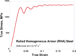
FIGURE 5-10 Stress-strain curve for RHA steel deformed in compression at a high strain rate. The oscillations in the curve are an artifact of the experimental technique and do not represent material behavior. The elastic response is also not captured accurately in such experiments. SOURCE: Zhang, H., J. Ye, S.P. Joshi, J.M. Schoenung, E.S.C. Chin, G.A. Gazonas, and K.T. Ramesh. 2007. Superlightweight nanoengineered aluminum for strength under impact. Advanced Engineering Materials 9(5): 355-359. Copyright Wiley-VCH Verlag GmbH &Co KGaA. Reproduced with permission.
These nontechnical factors surrounding the dual use potential and the economics of processing, metalworking, and joining are likely to continue to make metallic materials strong candidates for major components of robust and affordable armor systems. While the development of increasingly intense threats makes it less likely that an all-metal structure for armor will prevail, metals will probably continue to play an important role in cost-effective armor packages that can represent an optimal solution to an array of potential threats.
RHA continues to be the benchmark with respect to which most protection materials are judged: A typical objective is framed in relative terms—for example, “at least the performance of RHA at a lower areal density.” Although the performance of an RHA-based armor system is measured in terms of a specific threat, the fundamental stress-strain response is a good initial benchmark for materials design. A compressive stress-strain curve for RHA at high strain rates is shown in Figure 5-10. The dynamic strength is well over 1 GPa, and there is a small but distinct strain-hardening domain. A collection of such experiments over a range of strain rates provides an estimate of the strain-rate sensitivity of the flow stress, and similar experiments performed over a range of temperatures provides an estimate for the thermal softening of the flow stress. The constitutive behavior of metals such as steels and aluminum alloys can be relatively easily incorporated within a J2-flow type plasticity theory by associating the stress and strain mentioned above with the equivalent stresses and the equivalent strains. This kind of model is typically sufficient to describe the constitutive response of the metal at high strain rates. The parameters that define the overall behavior include the modulus, the yield strength in uniaxial tension or compression, the strain hardening, the rate sensitivity, the ultimate tensile strength in uniaxial tension, and the strain-to-failure in a uniaxial tensile test.
Desirable Attributes of Metals as Protective Materials
There is general agreement on some of the key features of good metal protection materials: high-strength, good ductility, some strain hardening, and some increase in strength with an increasing rate of deformation (“rate-sensitivity”). Other characteristics that are desirable include good form-ability so that the material can be formed into structures of the appropriate shapes, good long-term performance in the operating environment (e.g., corrosion and fatigue resistance), and weldability for ease of joining.
A commonly asked question about potential substitutes for RHA is whether their yield strength is on the order of 1 GPa. This strength-driven approach can be misleading, because in addition to a protection material’s basic constitutive behavior, its dynamic failure processes have a major influence on its performance in the face of a specific threat. The primary failure mechanisms consist of void growth under largely tensile conditions (typically defined by the spall strength133) and adiabatic shear localization134 under conditions of superimposed pressure and shear (both mechanisms are described in Chapter 3). The resistance of a metal to dynamic failure is essentially its resistance to spall and its susceptibility to adiabatic shear localization (the conventional properties of ductile fracture, while also relevant, are relatively well understood). The spall strength of a metal can be effectively bounded (at the lower end) using analyses such as those of Wu et al.,135 which incorporate the constitutive response, and the approaches of Molinari and Wright,136 which account for the internal defect distribution. The susceptibility to adiabatic shear localization is dependent primarily on the rate of thermal softening of the material and the strain-rate sensitivity.137 Thus the hardening and softening mechanisms within the material must be considered in addition to the mechanisms that simply raise the initial yield strength. For instance, many high-strength metals have very low rate sensitivity and may therefore be susceptible to adiabatic
______________
133Antoun, T., L. Seaman, D.R. Curran, G.I. Kanel, S.V. Razorenov, and A.V. Utkin. 2003. Spall Fracture. New York, N.Y.: Springer.
134Wright, T.W. 2002. The Physics and Mathematics of Adiabatic Shear Bands. New York, N.Y.: Cambridge University Press.
135Wu, X.Y., K.T. Ramesh, and T.W. Wright. 2003. The effects of thermal softening and heat conduction on the dynamic growth of voids. International Journal of Solids and Structures 40(17): 4461-4478.
136Molinari, A., and T.W. Wright. 2005. A physical model for nucleation and early growth of voids in ductile materials under dynamic loading. Journal of the Mechanics and Physics of Solids 53(7): 1476-1504.
137Wright, T.W. 2002. The Physics and Mathematics of Adiabatic Shear Bands. New York, N.Y.: Cambridge University Press.
shear localization. The degree to which each of these failure mechanisms is important for a specific material depends on the specific geometry of the armor structure as well as the specific threat; this means a detailed understanding of the connection between the microstructure and the failure mechanisms in the metal is important in the design of new metallic protection materials.
The mechanical properties of metals can be changed substantially by controlling the microstructure by chemical and thermomechanical means. Typical strengthening mechanisms include solid solution hardening, precipitation and dispersoid hardening, and grain boundary strengthening. In addition, many metals and metal alloys can be strengthened substantially by increasing the internal dislocation density through processes such as work hardening. This is one of the advantages of metallic materials: that the processing routes associated with metalworking can often be optimized to increase the strength and the ductility. An example of such a useful work-hardening route is rolling, which is typically used to produce plate geometries. Rolled metal can be much stronger than the metal before rolling, and indeed the largest tonnages of metallic armor materials are rolled alloys (such as RHA). Materials with submicron structural features are known to have higher yield strengths. Indeed, controlling not only grain size but also feature size—for example, in metals and bicontinuous composites like ceramic/polymer or metal/ceramic—can improve mechanical behavior.138,139
Finding 5-8a. Although metal alloys have been in use for many years, only a small fraction of the alloys in use have actually been characterized at the high strain rates relevant to ballistic problems. As a result, much of the modeling and simulation that is performed using these alloys has become heuristic rather than based on fundamental experimental data. This makes it very difficult to design with these alloys when new threats are presented. A sustained effort to develop a database of high-strain-rate material properties for metallic materials would benefit armor designers.
Appendix H provides a more detailed review of the main nonferrous metals that may (and sometimes do) compete substantially with steel: titanium and titanium alloys, aluminum and aluminum alloys, magnesium and magnesium alloys, and metal-matrix composites. A brief discussion on aluminum and magnesium and their alloys follows.
Aluminum and Aluminum Alloys
Aluminum and aluminum alloys were developed early in the twentieth century, and beginning around the time of World War II, they were pressed into service, beginning with armor for aircraft, to reduce weight. The introduction in the late 1950s of the T113 (later M113) vehicle type built of an aluminum alloy was followed by the deployment of significant quantities of aluminum alloys in the armored fleet. While pure aluminum is very soft, conventional aluminum alloys can have yield strengths that easily compete with those of the simpler steels. Specific approaches such as solid solution strengthening and age-hardening have been developed to strengthen Al alloys.
The trade-offs between weight, structural performance, ballistic performance, ease of production, and ease of maintenance, including resistance to corrosion, play a significant role in the choice of alloy for vehicular applications. Most of these aluminum alloys are used as rolled plate, and work-hardening alloys such as the 5000 series (5083 being the prime example) have some advantages. Aluminum alloys used as armor in Army vehicles include 2024, 2519, 5083, 5059, 6061, 7039, and 7075. Promising new commercial alloys include 2139 Al, a commercial alloy with significant strength (around 600 MPa at high strain rates) and reasonable ductility.
There is significant potential for the development of novel aluminum-based materials with very high strengths through alloying approaches and by the development of nanostructured systems and aluminum-based composites.
Finding 5-8b. There is a substantial potential for the development of new and improved aluminum alloys that can substitute for steel in military vehicles. Efforts to increase both strength and ductility of aluminum alloys at high strain rates are likely to bring significant benefits.
Magnesium and Magnesium Alloys
Magnesium has a remarkably low density of 1,700 kg/m3 (in comparison, Al is 2,800 kg/m3, Ti is 4,950 kg/m3, and steels are 7,800 kg/m3). Its density approach es that of polymers. Magnesium and magnesium alloys are thus among the lightest structural metals, and they are becoming increasingly important in the automotive and hand-tool industries. The rapid growth in the commercial use of magnesium is intimately tied to the increasing cost of energy. Their low density makes these materials very attractive for defense applications, but magnesium alloys have historically had relatively low strengths (~250-300 MPa) in comparison to aluminum alloys. There has also been lingering, albeit somewhat exaggerated, concern about the flammability of magnesium and about the relative ease with which these alloys corrode in severe environments. However, these concerns are relatively easily mitigated by proper design and appropriate protocols for maintenance.
______________
138Kraft, O., P.A. Gruber, R. Monig, and D. Weygand. 2010. Plasticity in confined dimensions. Annual Review of Materials Research 40: 293-317.
139Lee, J.-H., L. Wang, S. Kooi, M.C. Boyce, and E.L. Thomas. 2010 Enhanced energy dissipation in periodic epoxy nanoframes. Nano Letters 10(7): 2592-2597.
A substantial effort has begun over the last decade to generate high-strength magnesium alloys using a variety of approaches, including solid solution strengthening and precipitation strengthening. Commercial magnesium alloys that can substitute for some aluminum alloys include AZ31140 and ZK60, and several alloys containing rare earths show promise. Most of the innovation in this area is occurring abroad, particularly in China and Japan, and this may represent a long-term risk for the United States. A recent workshop at Johns Hopkins on the potential of magnesium and magnesium alloys as protection materials highlighted a variety of opportunities. One of the more promising strengthening approaches appears to be the development of ultra-fine-grained or nanostructured magnesium alloys through severe plastic deformation. A major research effort to gain a fundamental understanding of the strengthening mechanisms in magnesium alloys is likely to be very fruitful, and the opportunities presented by the metal’s low density should not be missed.
Finding 5-8c. A fundamental research effort to improve magnesium alloys could have a big impact on the weight of the armored vehicular fleet (a nascent effort exists at this time, driven by the ARL). There is a need to intensify research into other lightweight protective metals as well, which would help maintain the U.S. infrastructure for critical materials associated with protection systems for the warfighter. The outstanding performance of metals, the ease of fabricating and joining them, and the well-established industrial base ensure that these materials will be significant components of protection material systems for the foreseeable future. As the efforts in aluminum have demonstrated, there is a substantial potential for dramatic improvements even within the classes of metal alloys currently available.
ADHESIVES FOR ARMOR AND FOR TRANSPARENT ARMOR
Adhesive interlayers are key components of both ballistic glass and composite armor. Understanding, testing, and modeling of the adhesive interlayers in composite armor are crucial for their future design and improvement. Studies of nontransparent armor141as well as transparent armor indicate that the adhesives significantly influence the ballistic behavior of the composite structure. While results and material information are generally kept secret, published information on the subject provides insight into which adhesives are commonly used, the state of their development, and their modeling capabilities. Most interlayer materials are polymers, including thermoplastics and thermosets. The role of the adhesive is to hold the armor together before and after impact and to both deform and delaminate to absorb energy. These functions require an intermediate level of bonding between the adhesive and the hard components (glass, ceramic, metal)—neither too weak an interface nor too strong. Adhesives must absorb little to no light, because any absorption will lower the overall transmission of the transparent composite material. This applies not only to the visible wavelengths of light but also to the near-infrared as some applications are used with night vision goggles and sensors. As well as giving an overview of commonly used adhesives, this section also reports on design criteria for composites and their testing, both experimental and computational.
General Considerations for the Selection of an Adhesive Interlayer
Many material properties are important for the adhesives that are used as interlayers in armor and transparent armor applications. These include the strength of the adhesive bonds across the various interfaces, which is highly dependent on chemistry but also on surface roughness, environmental stability, mechanical impedances, mechanical properties over a very large range of strain rates, and transparency in the visible and near-infrared spectrum to name but a few. Figure 5-11 shows a cross-sectional view of a typical ballistic-resistant glass composite made up of a ceramic strike face, an outer region of plies of thick glass and alternating adhesive interlayers plus a transition section of a thick plastic (e.g., polyurethane) and an absorbing section, usually made of polycarbonate.
Important Issues Surrounding Adhesives for Lightweight Armor Applications
In automotive safety glass the strength of adhesion between the adhesive interlayer and the polymer, glass, and ceramic layers has been tailored with good effect.142,143,144Interlayers with bonds that can delaminate from the sub- and superstrates may better absorb a projectile’s kinetic energy. At the same time, however, they must retain enough integrity
______________
140Mukai, T., M. Yamanoi, H. Watanabe, and K. Higashi. 2001. Ductility enhancement in AZ31 magnesium alloy by controlling its grain structure. Scripta Materialia 45(1):89-94.
141Zaera, R., S. Sánchez-Sáeza, J.L. Pérez-Castellanos, and C. Navarro. 2000. Modelling of the adhesive layer in mixed ceramic/metal armours subjected to impact. Composites Part A: Applied Science and Manufacturing 31: 823-833.
142Fock, K., H.D. Hermann, K. Fabian, and J. Ebigt. 1987. Reduction in the Adhesion to Glass of Thermoplastic, Plasticized Polyvinylbutyral Molding Compositions. U.S. Patent 4,663,235.Available online at http://www.patents.com/us-4663235.html. Last accessed April 12, 2011.
143Hermann, H.D., K. Fabian, and J. Ebigt. 1985. Polyvinylbutyral Films Which Contain Plasticizer and Have a Reduced Adhesive Power on Glass. U.S. Patent 4,533,601. Available online at http://www.patents.com/us-4533601.html. Last accessed April 12, 2011.
144Garrison, W.E. 1969. Glass Laminate. U.S. Patent 3,434,915. Available online at http://www.freepatentsonline.com/3434915.pdf. Last accessed April 12, 2011.
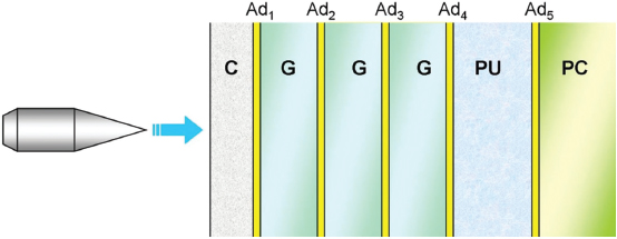
to minimize flying debris (spall).145 Additionally, the adhesion of the interlayer affects multi-hit performance; retaining and/or confining the hard ceramic and/or glass is necessary and so must be considered when designing interlayers.
Ultraviolet Radiation/Humidity/Temperature (Environmental) Stability
Service temperatures for armor can vary widely depending on where in the world it is deployed. Additionally, environmental degradation as a result of ultraviolet (UV) radiation or oxidation of the polymeric interlayer can affect both the transparency and the adhesive strength of the interlayer.
Strain-Rate Dependence
Most adhesive interlayers are for protection against ballistic threats. Thus, the properties of the adhesive at relevant strain rates must be known. Polymeric materials, of which most of the interlayers are made, typically have mechanical properties that depend greatly on strain rate and pressure.
Mechanical Impedance
Waves traveling through composite armor can be reflected or transmitted depending on the impedance mismatch between consecutive layers. Control of the mechanical impedance of the interlayer is therefore important in the design of the armor. The impedance of many polymers is only about 0.05 to 0.005 of that of ceramics, so that most (90 percent or more) of the incident energy is reflected from the ceramic-interlayer interface.
Thermal Expansion Coefficient
The coefficient of thermal expansion (CTE) of the adhesive interlayer is important for applications that will see a wide range of temperatures. Transparent armors are usually constructed with both high CTE (plastics such as polycarbonate) and low-CTE (ceramic and glass) materials. When directly bonded and exposed to a change in temperature, materials with much different CTEs will change in dimension by different amounts, resulting in stresses and deformation, including shape change and/or delamination. The CTE of the adhesive interlayer, along with its mechanical properties, can mitigate the effect of CTE mismatch in these systems.
Index of Refraction
Reflection from interfaces reduces the amount of light transmitted through a composite material. Ideally the refractive index of the interlayer material should be chosen according to the relationship ![]() with the thickness equal to a quarter wavelength so as to minimize reflection.146
with the thickness equal to a quarter wavelength so as to minimize reflection.146
Cost
Generally the cost of the adhesive is insignificant compared to that of armor materials such as AlON and sapphire.
Additional Functionality
The implantation of metal wires or conductive materials for resistive heating (for defogging, for instance) relies on the ability of the soft interlayer material to act as a host matrix. Implementation of heads-up displays or other electronics
______________
145Hou, S., and H. Reis. 2009. Adhesive bond evaluation in laminated safety glass using guided wave attenuation measurements. Pp. 33-44 in Advances in Ceramic Armor IV: Ceramic Engineering and Science Proceedings, Volume 29, Issue 6. L.P. Franks, ed. Hoboken, N.J.: John Wiley & Sons.
146Hecht, E. 2001. Optics, 4th edition. Old Tappan, N.J.: Addison-Wesley Longman.
are sometimes required, which places additional demands on the adhesive.
Glass Transition Temperature and Mechanical Loss Peaks
The transition temperature is key for processing and for providing a flexible material at the service temperature. Polymeric materials can absorb energy due to their many molecular motions. Such motions are temperature and frequency dependent and the associated mechanical loss peaks can be tailored for energy absorption in high-rate events.
Thermoplastic Polyvinyl Butyral
Developed in the late 1930s and commonly used in automotive glass applications, thermoplastic polyvinyl butyral (PVB), which is generally plasticized, has been the workhorse of polymeric adhesive interlayers. Examples are Saflex (Solutia, Inc.), Butacite (DuPont), Trosifol (Kuraray Europe), S-LEC (Sekisui Chemical), and KB (GlasNovations). Positive features of PVB include good optical transparency when bonded to glass, controllable adhesion to glass, resistance to elongation when struck with a projectile, and good UV stability.147
Thermoplastic Polyurethanes
Thermoplastic polyurethanes (TPUs) come in two broad categories, aliphatic or aromatic, depending on the precursor from which they are synthesized. Examples are Dureflex (Bayer Material Science), IM800 (and others from Inter Materials), Deerfield 4700 (and others from Deerfield Urethane), and Huntsman 399. Aliphatic TPUs are generally preferred for transparent armor applications because of their superior clarity compared to aromatic TPUs. TPUs are sometimes preferred to PVB since they do not contain plasticizer, which can chemically attack other polymers such as acrylics and polycarbonate.148TPUs are typically extruded and rolled in sheet form. The composite is formed by layering the materials, which are then sealed in a bag that is then evacuated of air and autoclaved to consolidate the layers.
Thermosets
Other cross-linkable polyurethanes may be used for adhesive interlayer materials. One such example uses a poly(urethane urea) elastomer.149 Blends of mercaptans with epoxies have shown improved performance.150 Epoxies for use as adhesives in nontransparent composite armor have also been studied.151
Other Materials
Thermoplastic poly(ethylene vinyl acetate), and low-temperature flowing glass or glass ceramics have been used as an interlayer for bonding alumina and sapphire or other high-temperature materials.152 Other hybrid materials specifically engineered for combining the adhesive and the rear panel are available from some manufacturers (e.g., FAENAC, a transparent plastic composite from Saint-Gobain Sully153,154).
Testing, Simulation, and Modeling of Adhesives
Adhesives are generally tested as part of a composite. It is the combined properties of the system that matter, and the interplay between the various hard components of the armor is transmitted via the adhesive interlayers. Chapter 2 of Advances in Ceramic Armor155 provides a good overview of destructive testing methods for adhesives. The simplest composite armor can be considered to be a ceramic plate adhesively bonded to a metal plate. An obvious question beyond the choice of material for the adhesive concerns the impedance and thickness of the adhesive. As for deformation and failure of the ceramic, an interlayer with a higher impedance is better since less of the energy would be reflected back from it as a tensile wave, and a thinner interlayer likewise is better. This is because more of the incident energy is more quickly transmitted to the metal layer, and when a compressive wave reflected from the interlayer-metal interface arrives at the ceramic, it helps to prevent bending and subsequent cracking of the ceramic. As for the metal, however, a thicker interlayer is better since it would spread the deformation
______________
147Freeguard, G.F., and D. Marshall. 1980. Bullet-resistant glass: A review of product and process technology. Composites 11(1): 25-32.
148 See http://www.bayerfilms.com/tpu/content.php?p=security-glaze for more information.
149 Sarva, S.S., and A.J. Hsieh. 2009. The effect of microstructure on the rate-dependent stress-strain behavior of poly(urethane urea) elastomers. Polymer 50(13): 3007-3015.
150 Uram, Jr., J.R. 1984. Moisture-Resistant Transparent Mercaptan Compositions. U.S. Patent 4,555,450. Available online at http://www.patents.com/us-4555450.html. Last accessed April 13, 2011.
151 Zaera, R., S. Sánchez-Sáeza, J.L. Pérez-Castellanosa, and C. Navarro. 2000. Modelling of the adhesive layer in mixed ceramic/metal armours subjected to impact. Composites Part A 31(8): 823-833.
152 Patel, P.J., G.A. Gilde, P.G. Dehmer, and J.W. McCauley. 2000. Transparent armor. The AMPTIAC Newsletter 4(3): 1-2.
153 Saint-Gobain Sully. Undated. Technical Datas FAENAC® Film. Available online at http://www.saint-gobain-sully.com/GB/quality/tech/FICHE%20TECHNIQUE%20FILM%20FAENAC%20A.pdf. Last accessed April 2011.
154 Jones, C.D., J.B. Rioux, J.W. Locher, E.S. Carlson, K.R. Farrell, B.C. Furchner, V. Pluen, and M. Mandelartz. 2009. Transparent Ceramic Composite Armor. U.S. Patent 7,584,689. Available online at http://www.freepatentsonline.com/7584689.pdf. Last accessed April 13, 2011.
155 Sun, X., K.C. Lai, T. Gorsich, and D.W. Templeton. 2009. Optimizing transparent armor design subject to projectile impact conditions. Pp. 15-22 in Advances in Ceramic Armor IV: Ceramic Engineering and Science Proceedings, Volume 29, Issue 6. L.P. Franks, ed. Hoboken, N.J.: John Wiley & Sons.
over a larger volume of the metal.156,157Clearly, detailed modeling and simulation can provide optimized solutions for armor design. Studies elucidating the influence of defects in plate materials158 have been conducted. The ARL is actively modeling transparent composite armor.159,160
Finding 5-9. There is need for an improved understanding of the dynamic behavior of the adhesive by itself and of the adhesive placed between dissimilar hard materials as part of an armor system.
Armor systems use different classes of materials—ceramics, metals, polymers, and composites—to meet defined ballistic threat requirements. The quality of the joints between dissimilar materials therefore plays an important role in the final armor performance, since these linkage sites have to withstand the dynamic loads under ballistic and blast conditions. With the increased use of diverse advanced materials, the number of armor joints is increasing and greater demands are being placed on them for better performance. Current methods of combining dissimilar armor material are somewhat empirical and based on experience with other products so that systematic research efforts are needed for understanding the dependence of ballistic performance on bond characteristics.
Joining different materials is often not an easy task.161 In general, bonding methods are chosen based on the particular materials to be combined, their geometrical configuration, and the performance requirements. In joining different materials careful attention has to be paid to minimize mismatches in properties and structural discontinuities. The key to a successful joint between dissimilar materials with different bonding characteristics and properties is the design of a buffer interface capable of accommodating the dissimilarities.162,163
The fundamentals that need attention when joining surfaces are surface roughness and surface contamination. When two surfaces are brought into contact, the true area of contact is less than the apparent area of contact owing to inherent surface roughness and the nonplanarity on an atomic scale of any surface. This inherent roughness is overcome by deformation, diffusion of surfaces (direct bonding), or infiltration of bonding filler between the two surfaces (indirect bonding). In armor systems, materials such as ceramics (for example, alumina, silicon carbide, or boron carbide) are bonded to metals (steels, aluminum, titanium, or magnesium), which in turn are joined to fibers, woven fibers, or polymer structures, mostly using indirect or mechanical bonding processes.
The selection of a technique for manufacturing a particular component will be based on a number of factors:
- Types of materials to be joined,
- Desired component function—for example, strength,
- Operational temperature,
- Applied mechanical stresses (static and dynamic) on
- the joint,
- Required level of joint airtightness,
- Component design, and
- Cost.
Mechanical joints typically have poor joint strength (10-50 MPa) and create areas of stress in ceramics, limiting design flexibility. Their use in armor applications164is thus restricted except where such conditions can be tolerated. In both indirect and direct bonding, charge or mass transfer can occur between surfaces.165 In indirect joining, an intermediate layer of filler alloy is used for bonding different surfaces. Examples of indirect bonding include soldering, brazing, adhesive bonding, and other processes that provide contact between the surfaces through the intervening filler materials. In contrast, direct bonding uses no fillers, and the bonding occurs by means of the solid-state processes that depend on deformation and diffusion between surfaces.
Bonding via solid-state diffusion requires the application of heat and long exposure times, while deformation requires relative sliding of surfaces with substantial applied stresses. Thus, while solid-state bonding methods yield
______________
156 Ibid.
157 Zaera, R., S. Sánchez-Sáeza, J.L. Pérez-Castellanosa, and C. Navarro. 2000. Modelling of the adhesive layer in mixed ceramic/metal armours subjected to impact. Composites Part A 31(8): 823-833.
158 Fountzoulas, C.G., J.M. Sands, G.A. Gilde, and P.J. Patel. 2009. Applying modeling tools to predict performance of transparent ceramic laminate armors. Pp. 45-53 in Advances in Ceramic Armor IV: Ceramic Engineering and Science Proceedings, Volume 29, Issue 6. L.P. Franks, ed. Hoboken, N.J.: John Wiley & Sons.
159 Fountzoulas, C.G., B.A. Cheeseman, P.G. Dehmer, and J.M. Sands. 2009. A Computational Study of Laminate Transparent Armor Impacted by FSP, ARL-RP-249, June. Available online at http://www.arl.army.mil/arlreports/2009/ARL-RP-249.pdf. Last accessed April 13, 2011.
160 MacAloney, N., A. Bujanda, R. Jensen, and N. Goulbourne. 2007. Viscoelastic Characterization of Aliphatic Polyurethane Interlayers, ARLTR-4296, October. Available online at http://www.dtic.mil/cgi-bin/GetTRDoc?AD=ADA474714&Location=U2&doc=GetTRDoc.pdf. Last accessed April 13, 2011.
161 do Nascimento, R.M., A.E. Martinelli, and A.J.A. Buschinelli. 2003. Review article:Recent advances in metal-ceramic brazing. Cerâmica 49(312): 178-198.
162 Paiva, O.C., and M.A. Barbosa. Brazing parameters determine the degradation and mechanical behaviour of alumina/titanium brazed joints. Journal of Materials Science 35(5): 1165-1175.
163 Howe, J.M. Bonding, structure, and properties of metal/ceramic interfaces: Part 2 interface fracture behaviour and property measurement. International Materials Reviews 38(5): 257-271.
164 Klomp, J.T., and G. de With. 1993. Strong metal-ceramic joints. Materials and Manufacturing Processes 8(2): 129-157.
165Martinelli, A.E. 1995. Diffusion Bonding of Silicon Carbide and Silicon Nitride to Molybdenum. Ph.D. dissertation. Montral, Canada: McGill University.
strong joints, they may not be suitable for most of the armor applications because dissimilar materials have different temperature tolerances and deformation characteristics. The role of temperature in joining dissimilar materials for a given set of surfaces is also an important operational parameter in selecting bonding media. The vast majority of joining processes involve heating surfaces that, upon cooling, develop residual stresses owing to mismatches in elastic modulus and CTE.
More often, the ceramic-metal joint in armor applications is achieved through indirect bonding processes. Adhesive joining is widely used. Even though adhesive joining with epoxy is executed under ambient conditions and is applicable to most materials, the resulting bond strength is relatively weak relative to brazing or soldering. Further, the low modulus of epoxy joints leads to a large elastic impedance mismatch with ceramic and metal, which could lead to poor ballistic performance.166 Very few adhesive materials exist with impedance close to that of metals and ceramics, because wave velocity depends on the elastic modulus and density of the material. The class of adhesives whose impedance most closely matches that of ceramics and metals is high-temperature ceramic adhesives. However, such ceramic adhesives are not as strong as polymer glues, and they are often used as matching layers in mechanically bonded systems. By combining ceramic adhesives with polymeric and other glues, performance could be considerably improved. Multilayer adhesives with better impedance match have demonstrated167 improved multi-hit ballistic performance and structural integrity.
Bonding options such as brazing and soldering typically result in higher modulus interfaces and thereby decrease (compared to adhesives) the elastic impedance mismatch with ceramic and metal substrates. Brazing or soldering ceramics to metal relies on wetting the ceramic surface with a suitable metal or alloy that will react with both the metal and the ceramic to form a joint. However, heating the surfaces to high temperatures develops residual stresses on cooling due to mismatches in elastic modulus and CTE. The heating temperatures for braze alloys are above 450°C and for soldering below 450°C. Achieving a superior brazed or soldered bond while minimizing residual stresses is important.
Mizuhara et al.168 developed an active brazing method in which the active component, such as titanium, is incorporated into silver-copper eutectic brazing alloys to enhance the wetting of ceramic and metal surfaces. This one-step vacuum brazing process wets most armor materials (ceramics, titanium alloys, and steels) and forms a superior metallurgical bond. However, the high processing temperature required for “active” brazing results in a large buildup of stress upon cooling owing to the different CTEs of metals and ceramics. Intermediate layers to alleviate expansion coefficient mismatches are being continuously developed, and the quality of the bond depends on filler layers that mediate the joining with minimum stress buildup.
Active soldering is an emerging technology similar to active brazing but performed at lower temperatures (<450°C) to reduce mismatch stresses during heating and cooling cycles. Here, reactive elemental titanium is added to the solder alloy as it is to a brazing alloy to enable direct wetting and bonding. The lower joining temperatures offered by active soldering minimize thermal stresses while yielding reasonable elastic impedance matching. Solder joint strengths are similar to those of epoxy joints. The tensile strength of an epoxy joint for bonding a hot-pressed SiC surface to an annealed Ti-6Al-4V surface is greater (73 MPa) than that of an active solder joint (43 MPa), while the elastic impedance of a solder joint is 10 times better than that of an epoxy joint, thus approaching the elastic impedance of ceramic and metal surfaces.
Finding 5-10a. Reliable methods for manufacturing dissimilar materials are in a nascent stage. Systematic studies to understand the relationships between ballistic performance, bond adherence, key filler material characteristics, and elastic impedance matching are needed to enable the manufacture of armor systems containing dissimilar advanced materials.
Finding 5-10b. Investment is needed in research and development in active brazing and soldering materials, adhesives, and processing methods for joining armor material to produce joints with minimal thermal mismatch stresses during the heating and cooling cycle of the bonding method.
OTHER ISSUES IN LIGHTWEIGHT MATERIALS
Nondestructive Evaluation Techniques
Nondestructive evaluation (NDE) techniques have been employed for the characterization of armor and armor materials for several decades.169 These techniques are preferred over destructive ones since they leave the material intact and ready for use. NDE tests of entire lots of materials can identify specific pieces that do not meet the appropriate criteria without having to rely on statistical interpolations of destructive test results carried out on a few select samples. Different evaluation techniques are applied to garner different kinds of information from the armor material. NDE is applied at various stages in the testing of armor to assess the performance capabilities of armor materials, to ensure the integrity of assembled arrays of tiles, and to understand how materials become damaged when introduced to various threats.
______________
166James, B. 2004. Practical issues in ceramic armor design. Pp. 33-44 in Progress in Ceramic Armor. New York, N.Y.: John Wiley & Sons.
167Ibid.
168Mizuhara, H., and K. Mally. 1985. Ceramic to metal joining with active brazing filler metal. Welding Journal 64(10): 27-32.
169See the American Society for Nondestructive Testing Web site at http://www.asnt.org/.
NDE testing focuses on determining whether materials for compiled armor assemblies will perform adequately when they are used in the field. This can be as basic as a simple go/no-go test or as complicated as a three-dimensional representation of internal flaws and density gradients. A variety of nondestructive methods has historically been used to rapidly locate and identify anomalous internal flaws in dense armor materials. These methods, which include resonant ultrasound spectroscopy, high-frequency ultrasound scans, infrared thermography, and microfocus x-ray computed tomography, are discussed in Appendix I.
Fiber-Reinforced Polymer Matrix Composites
Polymer matrix composites (PMCs), discussed further in Appendix J, consist of a polymer resin reinforced with fibers. One application is the combat helmet. PMCs can be subdivided into two categories based on whether the fiber reinforcement is continuous or discontinuous. PMCs with discontinuous fibers (less than 100 mm long) are made with thermoplastic or thermosetting resins, whereas PMCs with continuous fibers usually employ thermosetting resins.
The most common design for PMCs is a laminate structure made of woven fabrics held together by a polymer resin. Fabrics are incorporated to take advantage of their high strength and stiffness and to improve energy absorption and distribute the kinetic energy laterally. Owing to their highly engineered structures, PMCs are lightweight with high specific strength and high specific stiffness.
Common reinforcement materials are carbon, glass, aramid, and polyethylene fibers. PMCs can be manufactured by wet and hand lay-up, molding (compression, injection, and transfer), vacuum bag molding, infusion molding, vacuum-assisted resin transfer molding, prepreg170 molding, and other common techniques. Unlike the usual structural composites, which typically contain up to about 60 vol percent fibers, ballistic PMCs contain a higher volume fraction of fibers or fabrics, up to about 80 vol percent, although the effect of this variation in structure on the ballistic protection properties of PMCs has not been thoroughly investigated.
Because PMCs respond to ballistic impact in ways that depend on their particular structure, they are different from other protective materials. Unlike fabric materials, the PMC material responds only in the neighborhood of the impact position; thus the response is completely governed by the local behavior of the material and unaffected by the boundary conditions. Additionally, the penetration mechanism is dependent on the thickness of the composite. For thin composites, the deformation across the thickness direction does not vary with depth, while for thick composites it does.171Ballistic performance initially increases linearly with the increased thickness; however, as the composite becomes thicker, the marginal protective gain from increasing the thickness is less,172,173 while the rate at which the weight increases is maintained.
The overall findings of Chapter 5 are summarized below and are addressed by the recommendations presented in Chapter 6.
Finding 5-11. A sustained effort is needed to develop a database of high-strain-rate material behavior for the ceramic, polymeric, and metallic materials in use today and to expand the database as new materials are developed.
Finding 5-12. The intrinsic properties of opaque and transparent ceramics and ceramic powders are underrealized in armor systems. There is a need for an atomic, nano, and micron-size understanding of how powders and processing can be designed and manipulated to realize the benefits of dense and porous ceramic armor.
Finding 5-13. A need exists to build a production infrastructure for strategic ceramic powders within the United States for the next generation of opaque and transparent ceramic armor.
Finding 5-14. Current opportunities include the development of finer diameter and more ideal polymeric and carbon fibers with a two- to fivefold improvement in specific tensile strength over the current state-of-the-art fibers. Such improvements would lead to significant reduction in the weight of body armor.
Finding 5-15. Since polymers are often parts of systems (e.g., fabrics, matrixes, and reinforcing elements in composites), a fundamental understanding of how to model the deformation mechanisms and failure processes of polymers is critical to the successful large-scale modeling of complex multicomponent armor systems.
Finding 5-16. Advances are needed in test methods for determining the high-strain-rate (103 to 106 s–1) properties of fibers, polymers, and ceramics and their dynamic failure processes. Results could be used to develop a comprehensive database of strain-rate behavior for such materials.
Finding 5-17. The very low density of magnesium, including magnesium alloy fibers, could lead to the development of very lightweight alternatives to traditional metallic materials
______________
170Semifinished fiber products preimpregnated with epoxy resin (prepregs).
171Naik, N.K., and A.V. Doshi. 2008. Ballistic impact behaviour of thick composites:Parametric studies. Composite Structures 82(3): 447-464.
172Ibid.
173Faur-Csukat, G. 2006. A study on the ballistic performance of composites. Macromolecular Symposia 239(1): 217-226.
in protection material systems. A better basic understanding of the strengthening mechanisms in magnesium, especially the development of ultra-fine-grained magnesium alloys through severe plastic deformation, could be highly beneficial. Magnesium-based fibers are also worthy of exploration.
Finding 5-18. The development of bonding materials (adhesives, brazes, and solders) whose elastic impedances and thermal expansion coefficients match those of the materials to be bonded will improve the ballistic and blast performance of laminated armor.


