
If hydrocarbons unexpectedly flow into the well during drilling or other operations despite the use of primary barriers in the well, the blowout preventer (BOP) system serves as a secondary means of well control (i.e., preventing undesired hydrocarbon flow from the well). During offshore drilling, the system is deployed and attached to the wellhead to seal an open wellbore, close the annular portion of the well around the drill pipe or casing, or cut through the drill pipe with steel shearing blades and then seal the well. A typical BOP system also has more routine functions such as enabling certain well pressure tests and injecting and removing fluid from the well through its “choke” and “kill” lines. This chapter discusses the basic well control function of the BOP system that was part of the Deepwater Horizon mobile offshore drilling unit (MODU),1 general studies of BOP system reliability, the role of the BOP failure in the incident, and the results of forensic analyses of the recovered BOP system. The committee found several past studies and incident reports that documented the limitations of BOP effectiveness and reliability concerns, and they are discussed below. Unfortunately, it appears that neither industry nor the Minerals Management Service (MMS) responded to these past accidents in an appropriate manner. The chapter provides the committee’s findings and observations, as well as its recommendations for improving BOP system reliability.
BOP SYSTEM FOR DEEPWATER HORIZON
The BOP system for Deepwater Horizon was a massive, 57-foot-tall, approximately 400-ton well control system located at the wellhead (DNV 2011a, I, 15). A riser pipe attached to the top of the BOP system extended to the drilling platform on the Deepwater Horizon to permit drilling fluids to circulate between the borehole and the rig, passing through the BOP system. The bottom of the BOP rests on top of a remotely detachable connection to the wellhead, which allows the BOP to be released after well completion.
____________________
1The term “rig” is intended to be synonymous with mobile offshore drilling unit.
The BOP system was formed from two basic structural assemblies. The lower assembly, referred to as the BOP stack, rests on the wellhead connector. The upper assembly, referred to as the lower marine riser package (LMRP), was placed through a remotely detachable connection on top of the BOP stack and had roughly the same gross dimensions as the BOP stack. These assemblies, and basic functional components discussed below, are shown schematically in Figure 3-1. The LMRP had two annular preventers, and the BOP stack had four principal sealing elements: one blind shear ram (BSR) and three variable bore rams (VBRs). It also had a casing shear ram (CSR) that could shear drill pipe and casing but was not designed to seal the well. In addition, various control systems were located on the BOP system. In the event of an emergency disconnect, the LMRP was supposed to separate from the BOP stack, and the rig, riser, and LMRP were to move away from the well, which was to have been sealed by that point by the BSR in the BOP stack.
Annular Preventers
The LMRP contained two well-sealing components: the upper annular preventer and the lower annular preventer. The preventers were, as the name implies, annular in shape, and they were essentially flexible, elastomeric “doughnut” seals backed by steel elements that could accommodate a range of diameters of pipe and seal the annular space between the drill pipe and the LMRP. The annular seals were used so that the well could be tested, for example, for the so-called “negative test” discussed in Chapter 2, or potentially to stop any unwanted flow up or down the annulus.
In a blowout-prevention situation, the annular seals (if intact) could be activated and seal off the annular space between the pipe and the LMRP, although a blowout could still occur as a result of flow through the drill pipe itself if the drill pipe was not sealed.
A limiting factor was the maximum allowable differential pressure across the annular preventers. Reportedly, the upper annular preventer was designed for up to 10,000-psi differential pressure for sealing against a drill pipe or 5,000 psi when sealing the entire hole. The lower annular preventer was apparently designed for a 5,000-psi differential pressure for sealing around a drill pipe (BP 2010; Transocean 2011a).
Blind Shear Ram
The BSR was the uppermost of the five rams of the BOP stack and is shown for nominal operation in Figure 3-2. A BSR is like a massive metal scissors with two opposing blades that are designed to slice through the drill pipe as the blades pass by each other, as shown in Figure 3-3, and seal the well. The design intent was that, when the two blades of the “scissors” passed by each other and fully penetrated into the “side packers” on the other side, the seal
across the BOP bore was to be effected and thus seal off the entire throat of the BOP. The BSR was, by design, a device of last resort in a hierarchy of well control strategies: when all else failed, the BSR was to slice the drill pipe and seal the well. Even if no drill pipe was present in the BOP system, the BSR was designed to seal the well when the “scissor blades” passed by each other and into the side packers.
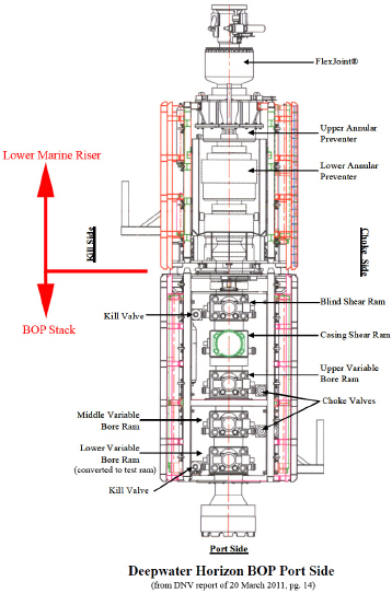
FIGURE 3-1 Deepwater Horizon BOP port side. Source: DNV 2011a, I, p. 14. Reprinted with permission; copyright 2011, DNV.
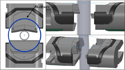
FIGURE 3-2 Sketch of intended nominal operation of BSR in the Macondo well. Source: DNV 2011a, I, p. 155. Reprinted with permission; copyright 2011, DNV.
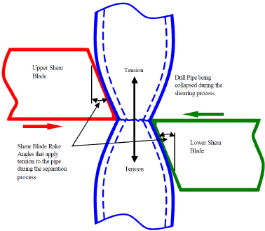
FIGURE 3-3 Upper and lower shear blades crushing the drill pipe and beginning the shearing (or breaking) operation. Source: West Engineering Services, Inc. 2004, p. 2-2. Reprinted with permission; copyright 2004, West Engineering Services, Inc.
The BSR was designed to be capable of activation in several ways (DNV 20011a, I, 2):
• By personnel on the Deepwater Horizon directly via either one of two control panels;
• Through the activation of the emergency disconnect system (EDS, with options EDS 1 and EDS 2) (BOEMRE 2011, 133), which was to function via either of the two control panels on the rig (the EDS was meant to be triggered when the drilling rig was to come off the well in an emergency for whatever reason);
• By the circuits located on either of two pods on the BOP system if the automatic mode function (AMF) was activated by loss of communications and hydraulic connection with the rig;
• By the autoshear function located on the BOP stack if the connection to the LMRP was physically broken; and
• By a subsea remotely operated vehicle (ROV).
The BSR is the only ram on the BOP that has automatic modes of operation: the AMF mode, which depends on the blue and the yellow pods, and autoshear mode, which does not depend on the control pods. All the other rams on the BOP are manually activated through the control pods.
Casing Shear Ram
The CSR was located below the BSR. It consisted of two pieces of metal with opposed V-shaped cutting tools above and below the plane of the slice. The CSR was designed to cut larger, thicker pipe than the BSR was designed to cut, such as casing rather than drill pipe. But the CSR, unlike the BSR, was not designed to seal off the BOP; it was designed only to cut pipe or casing.
Variable Bore Rams
Three VBRs were located near the base of the BOP stack, below the BSR and CSR. These rams had metal-reinforced elastomeric annular elements that, similar in function to the annular preventers in the LMRP, were designed to seal off the annular space between the drill pipe and the BOP system. The VBRs were more structurally robust than the annular preventers but were to close on only a narrow range of pipe diameters. The bottom VBR had been reversed to create a “test ram” that would seal against pressure in the riser instead of pressure in the well.
Control System
A number of components of the BOP control system were located on the BOP system itself, and the remainder were on the Deepwater Horizon. Two
electrohydraulic systems, termed blue and yellow “control pods,” which were housed on the LMRP, were key system control components on the BOP.
The control pods each contained electronic control units, which were connected to the drill rig with multiplexer (MUX) communication cables. A hydraulic line from the drill rig to the LMRP enabled the pressurization of the cylinder bank on the BOP system that held pressurized hydraulic fluid. The electronic control system opened and closed valves that allowed the pressurized hydraulic fluid to flow and to activate all rams and the seals in the upper and lower annular preventers.
The annular preventers and shear rams were driven by high-pressure hydraulic fluid that could have come from the rig, or—if connection with the rig was lost—from eight pressurized 80-gallon hydraulic accumulators on the BOP system. The accumulators contained high-pressure gas that was intended to push on the elastomeric bladders storing the hydraulic fluid. The high-pressure fluid initially pumped into the accumulators “charged” these accumulators. Electronic devices, when commanded, opened solenoid-driven valves that enabled the high-pressure hydraulic fluid to exit (driven by the gas in the accumulators). The high-pressure hydraulic pressure drove the rams (pistons) that displaced the preventers and rams. The electronic systems were complex and permitted control from the drilling rig, or—if communications were lost—were designed to self-initiate automated actions such as operation of the BSR.
Comments on Emergency Operations
The BSR is designed to be the true emergency sealing ram—it is the only one of the various rams on the BOP system that is designed to cut the pipe and seal the BOP system and hence the well. Sealing off the BOP system after slicing the drill pipe is a technical challenge but is well within the capabilities of current technology. The differential pressure above and below the BSR, if it works and seals, can be immense—thousands of pounds per square inch—creating enormous force and the need for high structural integrity, carefully engineered seals, and adequate testing under extreme conditions. After the metal pipe is sliced, fugitive metal from the sliced drill string cannot be permitted to become wedged between the slicing elements, which would prevent the slicing devices from fully closing and effecting a seal.
Further complicating the ram design envelope is the fact that the drill pipe joints (“tool joints”) are necessarily thicker than the drill pipe itself to accommodate geometrically the threaded portions of connecting drill pipe and to transmit the drilling torque between them. Transocean’s 2008 document Well Control Complications/Emergency provides background on the intended function of the BSRs. The Transocean document notes that “most BSRs are designed to shear effectively only on the body of the drill pipe. Procedures for use of BSRs must therefore ensure that there is no tool joint opposite the ram prior to drilling” (Transocean 2008, 2). Time and care are needed to ensure that no tool
joint is located in the plane of the BSR. Furthermore, the BOP system did not contain monitoring devices that would directly indicate the location of tool joints within the BOP system to the crew on the rig. Thus, to ensure that a tool joint is not present in the plane of the BSR, the drilling crew would have to position a tool joint at a known location, either by measurement and calculation of the tool joint positions or by “hanging” a tool joint on an underlying VBR.
The 2008 Transocean document does not address determination of tool joint location during time-critical situations. The documents states that “optimum shearing characteristics are obtained when the pipe is stationary and under tension” (Transocean 2008, 2). By analogy, cutting a string or cord with scissors is always easier if the string or cord is taut. But unlike regular string, drill pipe can transmit high compressive loads, particularly when it can use the side walls of the BOP for lateral stability. In the case of the Deepwater Horizon on April 20, 2010, the drill string above the BOP had a “dry weight”2 of more than 150,000 pounds.3 If an attempt is made to shear a drill string in compression, additional friction can be substantial. When a BSR is slicing the pipe, the slice is much easier to facilitate when the pipe is in tension (being pulled) rather than under compression. Under tension, the two pieces being cut are being pulled apart, away from the cut. If, instead, the drill pipe is in significant compression, the two pieces being cut are pressed against one another and pressing on the shearing blades, making the required shearing force much higher. Furthermore, under tension, the cut pipe would be pulled away from the rams, clearing the way for the rams to seal. Under compression, the pipe would tend to be jammed into the rams and therefore block full sealing. To keep the long slender drill pipe string in tension, it is hung off a “hook” that is attached to a “traveling block” whose vertical location can be moved up and down by a huge cable hoist in the drilling derrick. At the time of the explosion on the Deepwater Horizon, the dry weight of the entire drill string was 217,000 pounds, entirely borne by the hook and traveling block, and the total hook load hovered around 360,000 pounds (BP 2010, 105). Witness statements indicate in the case of the Deepwater Horizon that the rig’s traveling block, which carries the hook load (weight of the drill pipe string and upper works), fell at 22:20 (Transocean 2011a, I, 31), although the hook load itself could have been lost earlier as a result of damage from the explosions.
The design of the BOP system for the Deepwater Horizon focused on the use of the BSR under controlled conditions when tension in the drill pipe can be assured, and this appears to be the only way that BOP shear rams are tested. Tension would be lost, for example, if the drill pipe and the drill rig became disconnected because of an accident or explosion and the drill pipe moved downward into the well. Tension might be assured under carefully controlled
____________________
2The actual compressive load of this string at the BOP is slightly less due to the “buoyancy” of the steel relative to the weight of the fluids in the string, but not greatly.
3Transocean (2011a, I, 89), assuming 4,103 feet of 6⅝-inch string at 32.67 pounds per foot and 900 feet of 5½-inch string at 21.9 pounds per foot.
conditions, but not in an emergency (such as that encountered on the Deepwater Horizon) or in a number of other possible situations. Furthermore, since BOP ram testing is invariably done on the surface, the effects of a huge compressive pressure differential across the ram blocks are not revealed by the tests.
Some BOP systems have two BSRs as a remedy for the problem of a tool joint being in the wrong place, which can occur with a single BSR during an emergency. “All subsea BOP stacks used for deepwater drilling should be equipped with two blind-shear rams” was the conclusion of SINTEF (Stiftelsen for Industriell og Teknisk Forskning) in a study for MMS in 2001 (Holand and Skalle 2001, 96). The practice of using a single BSR that is incapable of cutting a tool joint raises serious questions about the overall reliability of the system in an emergency. The goal of future BOP designs should be high reliability under emergency conditions. How this requirement is met need not be prescriptively specified in regulation and may or may not require multiple BSRs. Regulation should require that emergency BOP reliability be empirically demonstrated by impartial testing under the most demanding conditions that would be encountered in an emergency.
The committee investigated the role that the BOP system failure played in the Macondo well–Deepwater Horizon disaster and identified what might be done in terms of BOP system design, operation, and maintenance to prevent such an occurrence in the future.
Prior Warnings That Existing BOP System Designs Were Inadequate
Before the Macondo well blowout, there were numerous warnings to both industry and regulators about potential failures of existing BOP systems. While the inadequacies were identified and documented in various reports commissioned over the years by industry operators and regulatory organizations alike, it appears that there was a misplaced trust by responsible government authorities and many industry leaders in the ability of the BOP to act as a fail-safe mechanism.
West Engineering Studies
West Engineering Services, Inc., conducted two studies (West Engineering Services 2002, 2004) on BOPs at the behest of MMS, now known as the Bureau of Ocean Energy Management, Regulation, and Enforcement (BOEMRE). The first, Mini Shear Study, apparently a preliminary study, was submitted in December 2002. The study was a review of shear ram test procedures from American Petroleum Institute (API) Specification 16A and results of
shear tests performed by rig operators on seven BOP systems. Fourteen cases were examined, but only seven included testing of BOP shearing capabilities. The study made several important points:
• “This study was designed to answer the question ‘Can a given rig’s BOP shear the pipe to be used in a given drilling program at the most demanding condition to be expected?’ This can only be demonstrated conclusively by testing.”
• “Of the seven [BOPs] tested, five successfully sheared and sealed based on shop testing only. If operational considerations [increased hydrostatic pressure] of the initial drilling program were accounted for, shearing success dropped to three of six (50%).”
• “This limited data set from the latest generation of drilling rigs paints a grim picture of the probability of success when utilizing this final tool in securing a well after a well control event.”
• “WEST is unaware of any regulatory requirements that state the obvious: that the BOP must be capable of shearing pipe planned for use in the current drilling program.”
The West Engineering study addressed the challenge of increased hydrostatic head to the BSR but did not address the even greater challenge of a large pressure differential across the rams as they attempt to seal. The West study addressed only the likelihood of the BSR shearing the pipe, not sealing it.
The West report indicates that drill pipe of a particular weight and grade may be the only pipe that a particular BOP shear ram is capable of cutting. In addition, the shear ram is unlikely to be able to sever drill pipe tool joints or heavy wall pipe such as drill collars. This means that careful housekeeping must be maintained to ensure that the correct type of pipe is in the correct position inside the BOP stack, particularly if only one shear ram exists on the BOP stack. Also, there is no automated means of ensuring that there is no tool joint in the BSR. This has to be done by (accurate) measurement and calculation.
The second study conducted by West Engineering Services, Inc., Shear Ram Capabilities Study, was submitted in September 2004. It expanded on the first study with theoretical and statistical studies of shear ram data from manufacturers, a review of BOP stack configurations, and a review of known BOP failures to shear and seal. The second report amplified the conclusions and observations of the first and made several additional points:
• Section 3.2 of the report states the following: “Improved strength in drill pipe, combined with larger and heavier sizes resulting from deeper drilling, adversely affects the ability of a given ram BOP to successfully shear and seal the pipe in use. WEST is currently aware of several failures to shear when conducting shear tests using the drill pipe that was to be used in the well. Only half of the operators accepting a new-build rig chose to require a shear ram test dur-
ing commissioning or acceptance. This grim snapshot illustrates the lack of preparedness in the industry to shear and seal a well with the last line of defense against a blowout.”
• The report reviewed one notable BOP “failure to shear and seal a well,” the Pemex blowout in the Bay of Campeche in 1979, which released 3.3 million barrels of oil before the well was killed. The report states the following: “Reportedly they were pulling the drill string too quickly without proper fluid placement and the well started coming in. They had no choice but to close the shear rams; unfortunately, drill collars were in the stack and shearing failed” (West Engineering Services 2004, 3-4). (Note: Drill collars are thick pieces of pipe used to provide weight and stiffness at the bottom of the drill string. The tool joint for the 6 ⅝-inch drill pipe had an outer diameter of 8.25 inches and an inner diameter of 4.625 inches at the upset for a wall thickness of 1.8125 inches. The drill collar would normally be thicker than this. For example, an 8¾-inch outer diameter drill collar could have an inner diameter around 3.25 inches for a wall thickness of 2.75 inches.)
• The method used by several BOP manufacturers for predicting whether the shear rams will successfully shear pipe and seal the well should be more accurate. Currently only tests can demonstrate the reliability of a shear ram with the particular pipe being used. The September 2004 study called on industry to develop better predictive methods and to establish a database that can be shared by all.
• In the cutting process, the shear rams collapse or mash the pipe, and as the pipe is crushed, the blade angle pulls the metal into tension and breaks it in a tensile mode of failure (Figure 3-3). Depending on the ram blade design, the blade can flatten the pipe to a great extent, which in turn can prevent the ram from closing completely and sealing even if the pipe is centered.
• CSRs were introduced to shear large-diameter, thick-walled pipe such as casing. These rams do not have a sealing mechanism so that the blade can be made strong enough to shear the thicker wall pipe. CSRs are installed in the BOP stack below the BSR so that the casing rams can be used to sever thicker pipe, and then the drill string above the casing rams can be raised out of the way so that the BSR can be closed and the well sealed. Some BOP stacks use a second BSR below the CSR to create a second opportunity to shear and seal the well, which basically ensures that at least one BSR will not have a drill pipe tool joint in front of it. However, in this situation, if the severed pipe cannot be removed from the BSR area it will likely not close sufficiently to seal.
• The various control systems on the rig are not integrated. Information from the BOP system is shown as indicator lights on the control panel on the rig, but no communication is made to the pipe-handling system to ensure that the pipe is in the correct position within the BOP system for well control operations.
• The second study also illustrated the challenge of keeping long-lived BSR designs from becoming obsolete. West stated: “There are two basic types of sealing shear ram designs: single [the type in the BSR of the Deepwater Hori-
zon] and double ‘V’ blades—rams with double ‘V’ blades appear to have 15% to 20% lower shear forces than single blade designs. The data received primarily included shear rams having both blades ‘V’ shaped.4 The two data points from shear rams that did not have both blades ‘V’ shaped [as was the case on the Deepwater Horizon] were excluded from statistical consideration” (West Engineering Services 2004, 4-2).
When a signal is sent from the drilling rig to the BOP (on the seafloor) to execute a command, the BOP sends a message back that the signal has been received. However, there are no devices to send a signal that any command has been executed, such as pressure or displacement sensors confirming that hydraulics were actuated or that rams have moved or that pipe has been cut, nor are there any flow sensors measuring whether the well has been sealed.
Additional conclusions can be drawn from the two West Engineering studies. Clearly, the operating success of the BSR was recognized to be much less than 100 percent years before the Macondo well blowout. It appears to be no better than 50 percent, on the basis of the results of the Mini Shear Study described above. This success ratio is inconsistent with the expectations placed on the BOP system as a fail-safe mechanism to close an out-of-control well. If well pressure is assumed to be contained by the annular preventer (assume the maximum rating of the annular preventer to represent this pressure) and if the well pressure differential across the BOP is assumed to be much larger than the hydrostatic pressure exerted by the drilling mud (as was the case in the Macondo well by at least two times), the shear success percentage demonstrated by the first study would decrease even further.
At no time is the drill pipe placed in compression during the tests discussed in the first West Engineering study. In fact, care is taken “to prevent excessive bending of the pipe” (API Specification 16A, Part B4.3.d [1997] (as cited in West Engineering Services 2004, 9-1)). The pipe section below the shear ram is not confined and is free to fall out of the shearing ram during operation. In contrast to this ideal test situation, if the pipe is in compression it may buckle as soon as the ram begins to shear it. The shear ram may not be able to cut the pipe in this condition. If the pipe is cut but cannot move out of the area of the closing rams, the rams may not seal. Sealing was not even considered in the study.
The careful housekeeping necessary to ensure that the correct type of pipe is in the correct position in the BOP stack may be difficult to accomplish in a well control emergency, further decreasing the chance that the shear rams will function correctly. Even with the addition of a CSR, the ability to seal the well is questionable if the pipe either above or below the CSR must be moved out of the way after the CSR cuts the pipe to allow one or more BSRs to seal the well. In a well control emergency there is no assurance, or even a likelihood, that the pipe can be moved at the appropriate moment to allow the BSR to seal. And obvi-
____________________
4See Figure 4.1 of West Engineering Services (2004).
ously, to ensure functionality, the BOP system design should accommodate pipe in compression and guarantee that sheared pieces of metal can be moved out of the way to allow the rams to seal.
On the basis of the West Engineering reports of 2002 and 2004, sufficient evidence of serious problems with the ability of the single BSR to meet expectations of functioning as a fail-safe device for closing an out-of-control well was available to industry and industry regulators. The problems identified in the reports for BOP systems with one BSR are compounded by the drill string being under compression, as exhibited during the Macondo well disaster. Neither of the West Engineering studies addressed the sealing capabilities or seal design of the BSR; they addressed only its ability to shear the drill pipe.
EQE Control System Risk Analysis
According to a risk assessment of the Deepwater Horizon BOP control system conducted by EQE International, a major contributor to the failure likelihood associated with the system was the selected stack configuration. “With only one shear ram available capable of sealing the well in, it is extremely difficult to remove all the single failure points from the system.”5 Specifically, (a) the final shuttle valve, which supplied hydraulics to the BSR, represented such a failure point and was predicted to account for 56 percent of the failure likelihood of the system to perform an emergency disconnect sequence, and (b) the failure of the four choke or kill valves each contributed about 5 percent of the failure likelihood of the EDS.6
According to the EQE assessment, the present shuttle valve design and its function, operation, and vulnerability to the single point failure need to be addressed systematically in the design and operation of a new-generation, post–Deepwater Horizon BOP system. EQE also indicates that overall, additional diversity and redundancy in the design would enhance reliability.
The next most important factor predicted by EQE to increase the risk for failure to disconnect was the human risk factor. The foremost requirement of declaring an emergency is a realization that the situation is in fact urgent. To reduce risk, EQE recommended that the frontline operator indicate, recognize, and be willing to initiate the appropriate actions or to switch to the standby pod following failure in the active pod. The BOP system should address human systems integration considerations. To ensure system reliability, the humans operating it must be willing and able to do their part.
____________________
5EQE International. 2002. Risk Assessment of the Deepwater Horizon Blowout Preventer (BOP) Control System. http://documents.nytimes.com/documents-on-the-oil-spill#document/p2. Most recently accessed Jan. 13, 2012.
6EQE International. 2002. Risk Assessment of the Deepwater Horizon Blowout Preventer (BOP) Control System. http://documents.nytimes.com/documents-on-the-oil-spill#document/p2. Most recently accessed Jan. 13, 2012.
The obvious command confusion on the bridge ultimately led to neither the master nor the offshore installation manager reaching a decision to execute the EDS until approximately 7 minutes after the first explosion. By that time, the subsea supervisor had already attempted to do so.
Limited Evolution in BOP Reliability
The BOP was originally invented by Cameron Iron Works, now Cameron International, in 1922. The BOP system used with the Deepwater Horizon was part of its TL series, based on the ram-type BOP design, which has matured and evolved over the years. In the absence of regulatory demand, the evolution of this expensive and long-lived piece of equipment appears to have been limited. However, advances in well-drilling technology, which have allowed for operation at greater water depths, presented a substantial challenge to the reliability of this basic BOP design. As other technological aspects of deepwater drilling continue to move forward, there is a need to improve BOP reliability.
However, several recent studies appear to suggest that BOPs can be trusted to act as a fail-safe mechanism. At a public forum convened by BOEMRE in September 2010 (5 months after the Macondo well blowout), an update on a study of subsea BOP reliability indicated that the probability of success of each BOP component tested was greater than 99 percent (Gallander 2010).7 Also, a finding of 99 percent “reliability on demand” for the BOP was published in a 2009 study conducted by Det Norske Veritas (DNV 2010). It found that BOP reliability on demand was 99 percent on the basis of hours of downtime divided by total hours the BOP had been installed, and the probability of success in sealing the well by a BOP with two BSRs was predicted to be almost 70 percent. Those reliability estimates were inconsistent with the West (2002) predicted 50 percent rate of operating success of BSRs.
Holand and Skalle (2001) mentioned a reliability study of a subsea BOP system that it had performed in 1999. The study focused on deepwater kicks and associated BOP problems and safety availability aspects. It was based on information from 83 wells drilled in water depths ranging from 400 to more than 2,000 meters (1,312 to more than 6,562 feet) in the U.S. Gulf of Mexico outer continental shelf (OCS). The wells had been drilled with 26 rigs in 1997 and 1998. A total of 117 BOP failures and 48 well kicks were observed. This number is inconsistent with the estimates of 99 percent mentioned above. DNV’s “reliability-on-demand” estimate of 99 percent does not reflect an important consideration for any crisis or panic situation: the drill pipe joints, which are nearly impossible for conventional BSRs to sever, make up 5 to 8 percent of the total pipe length. There is obviously a significant risk that a single BSR could be confronted with a tool joint and would fail to sever the pipe and seal the well-
____________________
7Information concerning the presentation was not included in the prepublication version of this report, which was issued in December 2011.
bore. The reasons might include the position of the joints relative to the BSR not being taken into consideration during activation of the BSR, the position of the joints moving because of flow and pressure from the well, or the hook on the rig holding the drill pipe dropping the load because of an explosion or mechanical failure. However, the 99 percent estimate appeared to be consistent with industry’s perception before the Deepwater Horizon incident that BOPs are safe and reliable. DNV (2010) apparently did not consider the challenge of shearing a tool joint in its analysis of the reliability of a BOP stack with one or two BSRs.
Other BOP Failures
Certain previous BOP failures reported by MMS, such as that reported in MMS 2001-009: Investigation of Blowout and Fire, Ship Shoal Block 354, OCS-G 15312 Well A-2, September 9, 1999 (MMS 1999, 5-6), provided ample warnings of the problem with compression in the drill tubing:
On the afternoon of September 9, 1999, while coiled tubing was being snubbed into Well A-2, it encountered an unknown obstruction that caused it to stop abruptly. Upon coming to a stop or shortly thereafter, the coiled tubing buckled and parted between the stripper assembly and the injector head resulting in the release of hydrocarbons to the atmosphere. [For coiled tubing rig up, see Attachment 2 of that report.] The pipe rams were closed and the shear rams were subsequently closed, thereby cutting the coiled tubing. The coiled tubing was then pulled back onto the coiled tubing reel. However, a section of coiled tubing remained between the shear rams and the injector head, where the original part [that is, the break in the tubing] had occurred. The blind rams were then closed but did not stop the flow of hydrocarbons because the coiled tubing stub was located across the blind rams. Attempts were then made to secure the well by closing the bottom manual valve on the BOP riser assembly, the crown (swab) valve, the surface safety valve, the bottom master valve, and the subsurface safety valve. The valves did not fully close because the coiled tubing remained below the shear rams and across the valve assemblies and the well continued to flow uncontrolled.
Role of BOP Failures on the Day of the Macondo Well Blowout (April 20, 2010)
Several critical conditions must be met for a BOP system to be used successfully:
• The BOP elements must be maintained and functional.
• The crew must recognize the signs of an impending blowout in time to take the appropriate action.
• The pipe must be positioned correctly in the BOP stack.
• The BOP elements must be actuated under well conditions allowing their limited designs to seal.
As discussed in Chapter 2, the crew of the Deepwater Horizon did not recognize the signs of the impending blowout in time to take the appropriate action. Several indicators that should have alerted the crew that hydrocarbons from the reservoir were flowing into the well were missed, such as the following:
• The continuing rebound in drill string pressure: The drill pipe had unexplained and uninvestigated trapped pressure during the third negative test.
• Excessive returns volume: The volumes of fluid that flowed from the well during the negative pressure tests exceeded the volume necessary to account for fluid compressibility, and the flow out from the well exceeded the flow in during displacement of mud from the riser.
• Several unexplained irregularities in pump pressure during and following the displacement of mud.
To assist the reader in understanding where in the blowout sequence various parts of the BOP system were activated, a timeline of events as postulated by different involved parties in the investigation is shown in Figure 3-4. Note that different parties have ascribed different times to the same event, although the discrepancies are not significant. The committee has made no independent attempt to verify the accuracy of these claims.
The record indicates that the BOP upper annular preventer had endured hard use on the Macondo well, which may have reduced its ability to seal on the day of the disaster. The crew had used the lower annual preventer for the negative pressure test, and that finally effected a seal after having its pressure increased, but not before leaking 50 bbl of spacer that required having its pressure increased (Transocean 2011a, I, 29; BP 2010, 84). Why the upper annular was activated for the blowout and not the lower is not clear. After the March 8 “well control event” on the Deepwater Horizon, OpenWells records: “Stripped drill pipe through upper annular preventer from 17,146 ft. to 14,937 ft. while addressing wellbore losses” (BP 2010, 22). Thus, with a standard drill string length of 46 feet per section, approximately 48 tool joints were stripped through the upper annular while it was closed.8 As SINTEF observed in a previous study, “But experience shows that when stripping is required as a part of the kick killing operation, this will cause that the annular is likely to fail afterwards (a failed annular preventer was observed after two of six stripping operations, described in Section 7.3.2 on page 81)” (Holand and Skalle 2001, 96). Despite the annulars having received hard use and being in need of maintenance, “the Panel
____________________
8(17,146 - 14,937)/46 = 48.02.
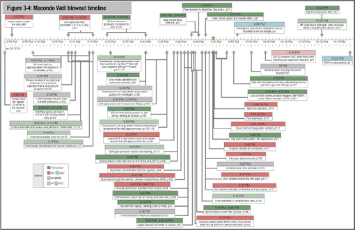
FIGURE 3-4 Macondo well blowout timeline. Source: Committee.
found that, less than a week before the blowout, BP informed Transocean that it wanted to defer maintenance to the upper and lower annulars (parts of the BOP stack)” (BOEMRE 2011, 150). In fact, BP was to confirm to Transocean that “B[P] accepts responsibility if both annulars were to fail and the stack had to be pulled to repair them.”9
At the Marine Board of Investigation hearings in New Orleans during April 4-8, 2011, witnesses for Transocean said that it based its decisions on condition inspections and tests of functionality and that it would not be uncommon to continue a BOP service for 10 years without a major overhaul if inspections continued to show no problems. With regard to requirements for a 5-year overhaul of the BOP, Mr. Fry contended that Transocean believed it was a recommended practice in the Gulf of Mexico under API RP 53 but was not mandatory.10
There has been much discussion of the extent of maintenance performed on the BOP, given battery voltages and solenoid problems. Such maintenance problems are inconsistent with a device with the important role of the BOP. Different parties to the disaster have widely disparate views on what maintenance was or was not done and on what inspections, both regulatory and contractual, were or were not satisfactorily passed by the Deepwater Horizon. However, the fact remains that all cognizant parties—commercial, regulatory, and governmental—agreed to or permitted the Deepwater Horizon’s being on station drilling on April 20, 2010. Given the primitive level of status monitoring innately provided by the BOP and its controls (not even the remaining charge on critical batteries was provided), the logical consequence should have been more intense maintenance, not less. This is particularly true in view of at least some of the primitive status monitoring being an explicit choice of Transocean. “Cameron offers an option for a rig to have the ability to monitor each pod’s battery voltages from any control panel. The Deepwater Horizon did not have this additional Cameron technology, which would have enabled the rig crew to monitor battery voltages” (BOEMRE 2011, 133).
But in the final analysis, the faulty design of the BSR, which would not shear and seal a modest 5½-inch-diameter drill string (well below its rating) in compression, significantly contributed to this national disaster. Given that there was only one BSR in the BOP system at the Macondo well and that it failed to stop the blowout because of its design and operational shortcomings, there is an urgent need for those shortcomings to be corrected.11
____________________
9BP-HZN-MBI00254591 in BORMRE (2011, 151).
10Testimony of Michael Fry, April 6, 2010, Hearing Before the Deepwater Horizon Joint Investigation Team, 72.
11To assist the reader in understanding where in the blowout sequence various parts of the BOP system were activated, a timeline of events is shown in Figure 3-4.
Forensic Analysis of the BOP
The committee reviewed the BOP forensic analysis work done on the Macondo well hardware recovered from the seafloor as part its overall evaluation of the available supporting evidence.
DNV (USA) was selected by the U.S. Coast Guard–BOEMRE Joint Investigation Team to conduct the forensic evaluation of the BOP. DNV is a risk management company providing a variety of services to the maritime and oil and gas industries, including materials testing and offshore classification. The forensic evaluations were conducted according to a test plan reviewed by a technical working group that included representatives from BP, Transocean, Cameron, the Chemical Safety Board, the U.S. Department of Justice, and the Multidistrict Litigation Panel and approved by the Joint Investigation Team.
The product of the DNV investigation was a final report (DNV 2011a) and the subsequent addendum (DNV 2011b). Both BP and Transocean have independently reported their earlier or additional investigations into why the BOP failed to perform as desired (BP 2010; Transocean 2011a).
The central finding of the DNV report was that the BSR blades could not shear a 5½-inch drill string and then seal against each other because the drill string was located on the side and not the center of the BOP annulus. This finding appears to be strongly supported by a wide range of corroborating physical evidence, and it has been embraced by Transocean (Transocean 2011a, I, 137). The asymmetric dents in the drill pipe sheared by the rams [impressed into steel 0.350 inch thick (DNV 2011a, I, 128)] credibly matched to the geometry of the ram blocks (DNV 2011a, I, 100) leave little room for alternative explanations. In addition, there is compelling physical evidence that the upper annular preventer above the BSR and the VBRs below the BSR were activated and closed on the drill string before the BSR was activated, centering the drill string in the BOP annulus in close proximity to the BSR. Thus, the DNV conclusion that the drill string was under significant compressive load also appears logical and perhaps the only feasible mechanism for pushing the drill string so far off center in such a short distance (27.3 feet) (DNV 2011a, I, 151). The consequence of not extending the blades on the BSR to cover the complete BOP annulus can be clearly observed in Figure 3-5. As was noted earlier, West Engineering dropped the one straight and one V-blade BSR configuration from its study in 2004 because of the higher shearing pressure this design required. It is also apparent that this configuration had less ability to center an off-center drill string than a double-V ram design would have evidenced. The gaps on the sides of the BSR blades, and their obvious inability to shear any pipe that was in this area, indicate that the possibility of pipe being off center was not considered in this design.
The source of the high compressive load on the drill string causing the “elastic buckle” (DNV 2011a, I, 150) driving it to the side of the annulus, calculated by DNV to be in excess of 113,000 pounds (DNV 2011a, I, 153), was not definitively determined. However, among a number of possible sources that it considered for this load, DNV hypothesized the following: “Forces from the
flow of the well induced a buckling condition on the portion of drill pipe between the Upper Annular and Upper VBRs” (DNV 2011a, I, 174). Further complicating the determination of the compressive load source is uncertainty about exactly when the BSR was activated, since different sources of compressive drill string load are potentially available only at certain times in the failure sequence. Two distinct BSR activation times have been hypothesized by the parties involved. Transocean maintains that both the blue (Transocean 2011a, I, 159) and the yellow (Transocean 2011a, I, 158) control pods were functional and available at the time of the explosion and loss of MUX and hydraulic connection to the Deepwater Horizon at 21:49, and therefore the AMF was functional and functioned “within minutes” (Transocean 2011a, I, 162) on April 20. However, BP and DNV have hypothesized, on the basis of the retrieved condition of the blue pod batteries (BP 2010, 150, 153) [74 days after the explosion (Transocean 2011a, I, 159)] and the incorrectly wired Solenoid 103 on the yellow pod (BP 2010, 150), that BSR activation was more likely due to the autoshear function, which bypasses Solenoid 103 and was caused by ROV intervention at 07:30 on April 22 (Transocean 2011a, I, 162).
Transocean [2011a, I, 157 (footnote G)] argues as follows:
The AMF system fired the HP shear circuit locking the ST Locks behind the upper and middle VBRs moments after the power was lost to the pods. If the AMF had not fired, the rams would have had to have been held closed by only the wellbore pressure for 33.5 hours until the auto-shear pin was cut by an ROV. When the auto-shear pin was cut on April 22, 2010, at 7:30 a.m., there was no indication of fluid discharge from the control pods indicating that the BSR and the ST Locks were already in the closed and locked position. If the BSR was still open, approximately 30 gallons of fluid would visibly discharge from the open side of the BSR and ST Locks.
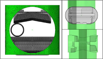
FIGURE 3-5 Finite element analysis model of BSR blade surfaces and off-center drill pipe. Source: DNV 2011b, p. 15. Reprinted with permission; copyright 2011, DNV.
But BP (2010, 156) has observed, not wholly inconsistently with Transocean’s claim:
In an effort to actuate and open the autoshear valve, the autoshear rod was cut at approximately 07:40 hours on April 21, 2010. Incident management team (IMT) responders, who were monitoring ROV operations when the autoshear was activated, reported that movement was observed on the BOP stack. This movement was consistent with stack accumulators discharging. A short time later, a leak on the ST lock hydraulic circuit, which was downstream of one of the BSR bonnet sequence valves, was observed, indicating that the lock circuit and the BSR were closed.
DNV (2011a, I, 169) independently observed:
While the conditions necessary for AMF/Deadman existed immediately following the first explosion/loss of rig power, because of the inconsistent behavior of original Solenoid 103Y and the state of the 27V battery bank on the Blue Control Pod, it is at best questionable whether the sequence was completed.
The weight of the evidence appears to support the conclusion of BP and DNV that the BSR was activated by the autoshear, but for additional reasons not addressed in their reports. All parties appear to agree that the upper and middle VBRs successfully sealed the well a minute or two before the explosions, accounting for the large pressure spike in the drill string starting at 21:47 (BP 2010, 105). Both these VBRs were found with their ST locks set (DNV 2011a, I, 31), meaning that they stayed applied, irrespective of flow or pressure, until the BOP was retrieved. Thus, until they were eventually eroded, the annulus of the BOP remained sealed by these VBRs. During this period the only flow path for hydrocarbons from the formation to the rig was the drill string. If Transocean was correct, this flow path was interrupted “within minutes” by the AMF activating the BSR. It appears undisputed that the BSR sheared the drill string off center in the manner illustrated by Figure 3-6, which is from the DNV report addendum (DNV 2011b, 17). If Transocean is correct and the AMF functioned “within minutes” of 21:50, then the entire hydrocarbon communication with the Macondo well must have been through the small flow area that would exist at that time from the sheared end of Pipe Segment 94 (End 94B) (DNV 2011a, I, 95). Note on Figure 3-6 in Frame 23 that the sheared pipe end is shown with only 277,000 pounds of ram load applied where the BSR will ultimately apply approximately 900,000 pounds of ram force at the regulated pressure of 4,000 psi (DNV 2011a, 14). Thus, substantially less cross-sectional flow area will be available to well hydrocarbons than is shown in Frame 23.
If the AMF functioned for at least some time, there should have been a significant reduction in hydrocarbon flow from the well that would have become
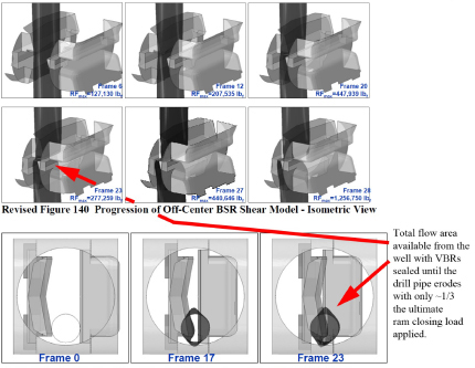
FIGURE 3-6 Progression of off-center BSR shear model, isometric view (top) and top view showing deformation of drill pipe outside of shearing blade surfaces (bottom). Source: DNV 2011b, p. 17. Reprinted with permission; copyright 2011, DNV.
apparent after the initial hydrocarbons that had leaked into the riser before the rams were activated blew out on the surface. This statement is true even if the explosions completely severed the drill string at the surface. After the drill string contents blew out, it would no longer have significant communication with the well for a period of time in the face of 900,000 pounds of clamping pressure on the output end of the severed drill string.
However, this scenario does not appear to be borne out by witness descriptions of the fire. “It was quickly apparent to the bridge team that it was impossible to regain control of the well or to fight the fires” (Transocean 2011a, I, 32). Several crew members jumped into the sea as the fire continued to grow in intensity (Transocean 2011a, I, 32). Thus, there appears to have been no interruption in flow from the well during the crucial minutes after the initial explosions, and the BSR rams appear not to have closed until the autoshear was activated.
Given the timing of the BSR activation, attention can now turn to the potential sources of the compression in the drill string that produced an off-center position in the BSR. Transocean produced several calculations consistent with the DNV hypothesis purporting to show that the pressure in the formation was sufficient to lift the drill string and create the necessary compression. The first is
set forth as: “5.5-in. drill pipe = 23.75 in.2 × 7,000 psi = 166,250 lb. lift” (Transocean 2011a, I, 157, Footnote E). This is Transocean’s assumed loading on the drill string after the VBR’s activation and presumably at the time of the postulated AMF activation, “within minutes” of the explosions. While the formula is mathematically correct, its application to the Macondo well drill string is difficult to see. To start with, 1 minute before the explosions, after the VBR activation, the internal drill string pressure on the rig shot up to more than 5,600 psi (BP 2010, 105). The bottom of the 5½-inch section of the drill string reached a depth of 7,546 feet below the drill rig floor (Transocean 2011a, I, 89). On the basis of the assumption that the entire length of drill string was filled with seawater being used to displace the drilling mud, at 0.445 psi per foot the seawater added another 7,546 × 0.445 = 3,358 psi of hydrostatic head to the internal drill pipe pressure measured on the rig, for a total pressure inside the end of the 5½-inch section of drill string of approximately 5,600 psi + 3,358 psi = 8,958 psi. The pressure measured on the rig in the drill string could only increase from about 1,200 psi to about 5,600 psi in 2 minutes if the formation pressure being exerted at the tip of the drill string was greater than the drill string pressure plus the hydraulic head of the total drill string (about 5,600 psi + 3,70712 psi), or about 9,307 psi, and flow was going into the drill string.
A different calculation of the same loading is set forth in Appendix M of Transocean (2011a): “In the shut in condition, the pressure below the VBR is 8,000 – 8,500 psi. With an assumed hydrocarbon density of 2 ppg above the VBR, the pressure above the VBR is 500 psi. Thus, the pressure drop across the VBR is about 8,000 psi, which corresponds to a net compression of about 120 kips” (Transocean 2011, Appendix M, 29). Needless to say, the two calculations do not agree.
Matters are different if it is postulated that the explosions on the rig ruptured the drill string and allowed the high drill string internal pressure to bleed down to atmospheric pressure at the rig. Such an event would leave only the 3,358 psi of hydrostatic internal pressure in the drill string, acting on the 4.8-inch internal diameter at the end of the 5½-inch section, for a total hydrostatic load of 60,765 pounds. This would be sufficient to reduce Transocean’s postulated lift by almost half and Transocean’s total calculated lift well below the compressive force level necessary at the BOP calculated by DNV. However, Transocean’s first lift calculation also ignored the weight of the drill string below the BOP. On the basis of the data for drill string dimensions and weights (Transocean 2011a, I, 89), this is calculated as 62,232 pounds dry weight, which corrects to 53,301 pounds buoyed by seawater. Transocean’s calculation in Appendix M would appear to take cognizance of the drill string weight, but neither appears to consider the pressure internal to the drill string. In both calculations Transocean treats the drill string as a piston, when in reality it is more like a straw, open at the bottom and the top after the explosions. The hydrostatic pres-
____________________
128,367 total feet of drill string × 0.445 psi/ft.
sure internal to the end of the 5½-inch drill string section and the buoyed weight of drill string below the BOP together produce 114,065 pounds of load. This must be overcome before the first pound of compression will be felt by the drill string in the BOP under any postulated failure scenario consistent with DNV’s hypothesis. An additional 821 feet of 3½-inch tubing is attached to the end of and hanging below the 5½-inch drill string, which is included in the calculations of buoyed weight but whose hydrostatically induced internal pressure would be even greater due to an additional 821 feet of head. Since the end of the 3½-inch tubing is opened to the flow from the formation and the top of the drill string has clearly been ruptured by the explosions, the area of the 3½-inch drill string is a “straw” that cannot be used in a calculation of compression load from pressure, so it is difficult to postulate a situation, short of some incredibly high flow rates, under which a significant pressure differential could be established between the inside and the outside of the drill string. Production of 115,000 pounds of drill string compression in the BOP as postulated by DNV requires that flow friction and pressure below the BOP generate a total of almost 230,000 pounds of vertical lift. There is a total of about 3,337 feet of drill string below the BOP. For fluid drag to produce the required vertical lift would require an average of 69 pounds of vertical fluid drag per linear foot of drill string. However, it is unlikely that the drag between the 3½-inch tubing and the 5½-inch drill string would be uniform, given that the flow is predominantly up the drill string, as evidenced by the erosion wear at the VBRs, which remain applied until the BOP is recovered. While the fluid drag is likely to be significantly greater in the 3½-inch tubing than in the 5½-inch drill string, use of even the 69-pound average means that the top of the 3½-inch tubing would experience a compressive load of 56,650 pounds. Whether the walls of this 9.3-pound-per-foot tubing can transmit a compressive load of 28 tons without local wall buckling is unknown.
Given the technical challenge of developing the 115,000 pounds of vertical compressive load on the drill string postulated by DNV through flow friction, gravity is a simple and attractive alternative. Above the BOP sit approximately 134,045 pounds of 6 ⅞-inch drill string and 19,710 pounds of 5½-inch drill string, for a total dry weight of 153,755 pounds of drill string. Corrected for buoyancy, this results in a net drill string weight at the BOP of 135,904 pounds. This is slightly more than the 115,000 pounds postulated by DNV as necessary to produce the observed elastic buckling in the drill string. While the rig’s traveling block was observed to fall about 30 minutes after the explosion, when vertical support of the drill string was lost is unknown. For the vertical mass of the drill string above the BOP to be the source of the compressive load in the BOP at the time of the application of the autoshear, the drill string must remain intact above the BOP. Transocean calculates that the drill string parted above the upper annular preventer through excessive tensile load at 21:56, approximately 6 minutes (Transocean 2011a, I, 157) after the explosions, as the powerless Deepwater Horizon drifted off station. Transocean’s assumptions about the integrity
of the derrick after the explosions and its support of the weight of the drill string are not set out.
DNV (2011a) hypothesized that the drill string “would have been set in slips to remove the suspended load from the derrick or travelling block.” However, there is no available evidence of this or of how the slips would have fared in the two explosions even if they had been used. As illustrated by BP (2010, 105, Figure 17), the hook load measured the weight of the drill pipe, top drive, blocks, and so forth right up to the moment of explosion. The slips were not set. While DNV (2011a) did not consider it likely that the two VBRs applied simultaneously with full rig hydraulics still connected could have generated the gripping force necessary to support the compression, no data or tests were presented in support of this hypothesis.
Summary Finding 3.1: The loss of well control was not noted until more than 50 minutes after hydrocarbon flow from the formation started (see timeline in Figure 3-4), and attempts to regain control by using the BOP were unsuccessful. The BSR failed to sever the drill pipe and seal the well properly, and the EDS failed to separate the lower marine riser and the Deepwater Horizon from the well.
The EDS failed to operate because of the loss of MUX communication in the explosion or the subsequent fire which burned for 7 minutes on the rig floor before EDS activation was attempted.
Finding 3.2: The crew did not realize that the well was flowing until mud actually exited and was expelled out of the riser by the flow at 21:40. Early detection and control of flow from a reservoir are critical if an impending blowout is to be prevented by a BOP whose use against a full-flowing well is untested.
Finding 3.3: Once mud began to flow above the rig floor, the crew attempted to close the upper annular preventer of the BOP system, but it did not seal properly. The BOP system had been used in the month previously to strip 48 tool joints, and apparently it was untested for integrity afterwards. Annulars are often unable to seal properly after stripping. In addition, the flowing pressure inside the well may have been larger than the preset annular closing pressure could overcome. What tests of sealing against flow have been done on this design of annular are unknown.
Finding 3.4: The crew also closed the VBRs. The damaged pipe under the upper annular demonstrated its failure to seal, and the well was
only sealed, resulting in the final pressure spike, when these VBRs were closed. The DNV investigation also found that these rams closed, and they could only be closed by command from the rig control panels and not by an ROV. At this point the flow from below the VBRs would have been closed off, but gas and oil had already flowed into the marine riser above the BOP system and continued to rise to the surface, where the gas exploded.
Finding 3.5: The internal BOP, which functions as a safety valve on the top of the drill pipe, was not closed (BP 2010, 25). Also, approximately 30 minutes after the explosion the traveling block was observed to fall and the rotary hose (used to conduct drilling fluid) could have been destroyed. The growing fire indicates that the drill pipe was broken in the initial explosion and the fall of the traveling block could have allowed even more flow to escape up the drill string. This was the likely path of hydrocarbon flow before the closure of the BSR (see Chapter 2).
Finding 3.6: Once the fire started on the rig, an attempt was made (after 7 minutes) to activate the EDS, which should have closed the BSR and disconnected the LMRP. This appears to have failed because the MUX communication cables were destroyed by the explosion or fire.
Finding 3.7: Once hydraulic and electrical connection with the rig was lost at the BOP, the AMF should have activated the BSR. It might have failed at this time because of a low battery charge in one control pod and a miswired solenoid valve in the other, but both these points are in dispute. However, no short-term reduction in hydrocarbon flow from the well was observed after the initial fire and explosion (see Figure 3-4). Such a reduction would necessarily have resulted from the VBRs sealing the annulus in the BOP and the failed BSR shearing action effectively choking, at least for a brief period of time, virtually the entire cross section of the 5½-inch drill string. Viewed in total, the evidence appears more supportive of the autoshear activation of the BSR.
Finding 3.8: The BSR appears to have been activated after 07:40 on April 22, 2010, if not earlier, when the hydraulic plunger to the autoshear valve was cut by an ROV. However, regardless of when the BSR was activated, the well continued to flow out of control.
Finding 3.9: DNV hypothesized that the drill pipe below the annular preventer was being forced upward by the pressure of the flowing well, resulting in a 115,000-pound net compressive force on the drill pipe in the BOP sufficient to buckle the drill pipe until it came in con-
tact with the inside of the BOP system (DNV 2011a, I, 174). However, the fluid mechanics inherent in this assumption are dubious. The 135,000 pounds of buoyed drill string weight above the BOP appears to be a more plausible source of the compression.
Finding 3.10: When it was activated, the BSR was unable to center the drill pipe in its blades and failed to cut the pipe completely. The blades of the ram were of the old straight and V combination, which has been shown to be inferior in its shearing performance to the double-V blade geometry (West Engineering Services 2004). Because the BSR blades did not fully span the BOP annular, a mashed segment of pipe was caught between the rams and prevented them from closing to the point where they could seal (DNV 2011b, 17) (see Figure 3-6).
An alternative hypothesis for compressive loading on the drill pipe is that the loading could have occurred if the drill string were dropped from the top drive in the derrick. This equipment likely had been damaged or destroyed by an explosion and fire. A closed VBR would act to restrict the motion of the drill pipe. The drill pipe above the BOP would go into a long helical buckle above the ram and in the marine riser, placing a considerable compressive load on the drill pipe in the BOP system. On the basis of solid mechanics, a pressurized tube reacts as if it is under compressive load.
Under either of the scenarios mentioned above, the buckling force would have occurred as soon as the elements of the BOP system prevented the upward or downward motion of the drill string, and clearly there are several plausible reasons why the drill string would have been in compression.
Finding 3.11: After the rig lost power and drifted off station, the marine riser kept the vessel tethered to the BOP system.
Finding 3.12: Flow from the well then exited the partially severed drill pipe in the BSR and began to erode parts of the ram and BOP stack by fluid flow.
Finding 3.13: After the vessel sank at 10:22 on April 22, 2010, the marine riser with the drill pipe inside was bent at a number of places, including the connector to the BOP, and oil and gas began to flow into the ocean.
Finding 3.14: The effect of closing the CSR on April 29, 2010, was to provide a new flow path exiting the severed drill pipe below the CSR and passing the CSR rams that were not designed to seal. Severe fluid erosion occurred past the CSR, with deep cuts made in the surrounding steel of the BOP housing itself, endangering the integrity of the housing.
Finding 3.15: Unfortunately, even if the BSR had functioned after being activated by the EDS or the AMF, it would not likely have prevented the initial explosions, fire, and resulting loss of life, because hydrocarbons had already flowed into the marine riser above the BOP system. If the BOP system had been able to seal the well, the rig might not have sunk, and the resulting oil spill would likely have been minimized.
Summary Finding 3.16: The BOP system was neither designed nor tested for the dynamic conditions that most likely existed at the time that attempts were made to recapture well control. Furthermore, the design, test, operation, and maintenance of the BOP system were not consistent with a high-reliability, fail-safe device.
Finding 3.17: Regulations in effect before the incident required the periodic testing of the BOP system. However, they did not require testing under conditions that simulated the hydrostatic pressure at the depth of the BOP system or under the condition of pipe loading that actually occurred under dynamic flow, with the possible entrained formation rock, sand, and cement, and no such tests were run. Furthermore, because of the inadequate monitoring technology, the condition of the subsea control pods at the time of the blowout was unknown.
Finding 3.18: The committee’s assessment of the available information on the capabilities and performance of the BOP system at the Macondo well points to a number of deficiencies (listed below) that are indicative of deficiencies in the design process. Past studies suggest that the shortcomings also may be present for BOP systems deployed for other deepwater drilling operations.
1. The committee could find no evidence that the BOP design criteria or performance envelope was ever fully integrated into an overall well control system perspective, nor that BOP design was consistent with the BOP’s critical role in well control.
2. While individual subsystems of various BOP designs have been studied on an ad hoc basis over the years, the committee could find no evidence of a reliability assessment of the entire BOP system, which would have included functioning at depth under precisely the conditions of a dynamic well blowout. Furthermore, the committee could find no publicly available design criteria for BOP reliability.
3. The entire BOP system design is characterized by a previously identified lack of redundancy:
- There is only one BSR.
- One shuttle valve is used by both control pods.
- Each MUX cable is incapable of monitoring the entire BOP system independently.
4. No design consideration appears to have been given to BSR performance on pipe in compression.
5. The BSR was not designed to shear all types and sizes of pipe that might be present in the BOP system.
6. The BSR probably did not have the capability of shearing or sealing any pipe in significant compression.
7. There was a lack of BOP status monitoring capabilities on the rig, including
- Battery condition,
- Condition of the solenoid valves,
- Flow velocity inside the BOP system,
- Ram position,
- Pipe and tool joint position inside the BOP system, and
- Detection of faults in the BOP system and cessation of drilling operations on that basis.
Finding 3.19: The failure of the AMF to activate might have been due to malfunctions in the control pods that could not be detected. In view of the state of the pipe in the well after the explosion, whether the BSR would have functioned properly is uncertain. This issue is moot if the rams could not perform their intended functions whenever they were activated.
Finding 3.20: The regulations did not require that the design of the equipment allow for real-time monitoring of critical features, such as the battery condition in the control pod, so that maintenance issues could be readily discovered. The current test protocol for the BSRs, for example, is designed for near-ideal surface conditions rather than the harsher conditions found on the ocean floor.
Finding 3.21: When a signal is sent from the drilling rig to the BOP (on the seafloor) to execute a command, the BOP sends a message back that the signal has been received. However, there are no transducers that detect the position or status of key components, and there are no devices to send a signal that any command has been executed (such as pressure or displacement sensors confirming that the hydraulics have been actuated, that rams have moved, or that pipe has been cut). Furthermore, there are no sensors to communicate flow or pressures in the BOP to the rig floor.
Observation 3.1: In the confusion of an emergency such as the one on the Deepwater Horizon, it is not surprising that a drill crew would not take the time to determine whether a tool joint was located in the plane of the BSR or whether tension was properly maintained in the drill pipe.
Observation 3.2: In terms of emergency procedures, such as an emergency disconnect or autoshear function of the BOP system on its own, there is no ability to manipulate the tool joint position or the level of tension or compression in the drill pipe. The BSR was not designed to work for the full range of conditions that could be realistically anticipated in an emergency.
Summary Recommendation 3.1: BOP systems should be redesigned to provide robust and reliable cutting, sealing, and separation capabilities for the drilling environment to which they are being applied and under all foreseeable operating conditions of the rig on which they are installed. Test and maintenance procedures should be established to ensure operability and reliability appropriate to their environment of application. Furthermore, advances in BOP technology should be evaluated from the perspective of overall system safety. Operator training for emergency BOP operation should be improved to the point that the full capabilities of a more reliable BOP can be competently and correctly employed when needed in the future.
Recommendation 3.2: The design capabilities of the BOP system should be improved so that the system can shear and seal all combinations of pipe under all possible conditions of load from the pipe and from the well flow, including entrained formation rock and cement, with or without human intervention. Such a system should be designed to go into the “well closed” position in the event of a system failure. This does not mean that the BOP must be capable of shearing every drill pipe at every point. It does mean that the BOP design should be such that for any drill string being used in a particular well, there will always be a shearable section of the drill pipe in front of some BSR in the BOP.
Recommendation 3.3: The performance of the design capabilities described in the preceding recommendation should be demonstrated and independently certified on a regular basis by test or other means.
Recommendation 3.4: The instrumentation on the BOP system should be improved so that the functionality and condition of the BOP can be monitored continuously.
Summary Recommendation 3.5: Instrumentation and expert system decision aids should be used to provide timely warning of loss of well control to drillers on the rig (and ideally to onshore drilling monitors as well). If the warning is inhibited or not addressed in an appropriate time interval, autonomous operation of the BSRs, EDS, general alarm, and other safety systems on the rig should occur.13
Recommendation 3.6: An unambiguous procedure, supported with proper instrumentation and automation, should be created for use as part of the BOP system. The operational status of the system, including battery charge and pressures, should be continuously monitored from the surface.
Recommendation 3.7: A BOP system with a critical component that is not operating properly, or one that loses redundancy in a critical component, should cause drilling operations to cease. Drilling should not resume until the BOP’s emergency operation capability is fully cured.
Recommendation 3.8: A reliable and effective EDS is needed to complete the three-part objective of cutting, sealing, and separating as a true “dead man” operation when communication with the rig is lost. The operation should not depend on manual intervention from the rig, as was the case with the Deepwater Horizon. The components used to implement this recommendation should be monitored or tested as necessary to ensure their operation when needed.
If the consequence of losing communication and status monitoring of the BOP system is an automatic severing of the drill pipe and disconnection from the well, the quality and reliability of this communication link will improve dramatically.
Recommendation 3.9: BOP systems should be designed to be testable without concern for compromising the integrity of the system for future use.
____________________
13This recommendation is also presented in Chapter 4 as Recommendation 4.1.


