
4
Engineering Considerations
Even with improvements in crew training, tank vessel operation, and navigation, accidents will occur. The effects sometimes can be mitigated by design. This chapter addresses engineering considerations related to tanker design as they affect oil outflow in collisions and groundings. Some of the same considerations apply to ocean-going barges. Arguments frequently offered for or against particular design features are addressed here from an engineering viewpoint.
In the context of the full report, this chapter reflects practical issues resulting from the physical phenomena explained in Chapter 3. Further, these discussions are intended to provide an understanding of issues that are basic to any evaluation of tank vessel designs. The overall assessment of specific designs mentioned in the following pages can be found in Chapter 5.
The topics to be discussed in this chapter include: hull strength; tank proportions, arrangements, and stability; salvage concerns; and safety of life.
HULL STRENGTH
When a tanker is damaged by collision or grounding, with resultant outflow of cargo, the hull obviously has failed. Its strength was insufficient to survive the trauma. Hull failure also can result from improper loading, design or construction flaws, corrosion, explosions, or fires. To understand all of these situations, a brief review of structural design principles will be useful.
Design Loads, Stress Analysis, and Scantling Selection
The loads considered in tanker structural design include ship and cargo weight, internal and external hydrostatic pressure at all angles of heel and trim,1 wave loads, and dynamic components resulting from induced motions. (A more detailed discussion can be found in Appendix B.) These loads are variable and many act simultaneously. They can be broken down into the following components:
-
internal/external liquid pressure differentials;
-
shear forces generated by the non-uniform distribution of ship weight, cargo, and buoyancy along the length of the vessel, both in still water and in waves; shear is important in webs and girders (support framing), as well as side structure and longitudinal bulkheads;
-
hull bending moment2 caused by unbalanced longitudinal distribution of buoyancy and weights;
-
wracking (twisting) loads, tending to distort the hull's shape, caused by oblique seas, asymmetrical loading, etc.;
-
impact loads such as the slamming of the ship's forward body during heavy pitching;
-
the weight of water on deck caused by heavy seas;
-
sloshing loads on bulkheads caused by impact loads of cargo motions in partially filled tanks; and
-
thermal loads caused by unequal temperatures such as from heated cargo.
Many of these loads can be present at any given time, even if a ship is in still water without wave loading and dynamic effects. Loads commonly cause a combination of tensile and compressive forces in both plate and girder structures; shear forces are imposed simultaneously on some components. With the presence of both compressive and shear forces, the possibility of buckling must be considered. This is increasingly true as ships increase in size, because plating and beam structures generally do not increase proportionally in thickness.
Ship designers have been aware of these principles for decades, but historically, in practice, they were limited to simplified definitions of loads. Designers compensated by applying time-tested margins, which allowed for imperfect theoretical understanding of loads. Margins also made up for design shortfalls and allowed for corrosion, material flaws, fabrication error, and operational mishaps.
In the 1960s, the availability of computers, coupled with improved understanding of oceanographic data, enabled naval architects to define more precisely the dynamic loads experienced by a ship, and to evaluate the response to those loads. In short, designers had a more rational basis for
analysis and were able to produce more efficient designs. Traditional margins—or ''safety factors"—were pared back, and ship structure became relatively lighter, or less robust.
In the meantime, the size of tankers increased dramatically, as described in Chapter 2. To compound the stress on ship structure, competitive pressures of the 1980s placed an additional premium on lighter (cheaper) designs, and classification societies further relaxed traditional margin requirements where a rational basis for design could be demonstrated. Because use of high-tensile steel could reduce hull weight further, this material proved increasingly popular. This introduced new concerns, e.g., corrosion margin, fatigue life, and tighter construction requirements. The net result was that the proportion of non-revenue-producing hull structure in tankers dropped dramatically over a 20-year period (as was shown in Table 2-1). As a result, modern hull structure is relatively less able to resist unexpected loads such as from grounding or collision.
The history of engineering provides a number of examples of design refinement and rapid growth in structure size leading to novel and unforeseen difficulties. A land-based example goes back to the early 1940s when natural gas pipelines were first being built to bring southwestern gas to the industrial Northeast. Several catastrophic failures occurred to these new lines (causing deep and long furrows along the right-of-way), which were the first to come north and by far the longest lines then in service. Knowledge of the principles of fracture mechanics grew with the awareness that the combination of long pipeline sections between connections and the cold weather environment made ideal conditions for fracture propagation.
With that image as a prelude, the engineering difficulties posed by advances in tanker design will be discussed in the following pages.
Design Margins
As noted previously, modern tankers have less design margin (Ferguson/Lloyd's Register of Shipping, 1990; Iarossi/American Bureau of Shipping, 1990) than they did in the past, whether it be the ability to accept flaws in design details, material quality, manufacturing errors, corrosion, or operations. Overall, they are less robust than their predecessors.
A major consequence is increased risk from corrosion—higher induced structural deterioration. All shipbuilding steels corrode at the same rate unless effective protective measures, such as coatings and/or anodes, are applied and maintained. Thus, if the thickness of plates and stiffening members is reduced, because of changes in design criteria and materials, there is less margin left to corrode before the structure is subject to possible failure. Large tankers built in the late 1950s and early 1960s commonly had deck and bottom plate thicknesses on the order of 30-35 mm. These
TABLE 4-1 A Comparison of Segregated Ballast Areas in a 260,000 DWT Tanker
|
Tanker Type |
Total Area of Ballast Spaces* (flat plate area without stiffeners) |
|
Pre-MARPOL |
7,000 square meters |
|
MARPOL |
23,000 |
|
Double Bottom |
34,000 |
|
Double Sides |
39,000 |
|
Double Hull |
64,000 |
|
* Figures are rounded off to the nearest thousand. |
|
plates now are typically only about 20 mm thick. Wastage of unprotected steel proceeds at a constant rate; at 0.5 mm per year, for example, an unprotected 35 mm plate will be reduced to 30 mm after 10 years, a reduction of 14 percent. By contrast, the exposed portion of the 20 mm plate, also reduced by 5 mm in ten years, will be reduced by 25 percent. Thus, adequate corrosion protection is much more critical in newer ships than in older ships.
Compounding this concern is the fact that MARPOL tankers, due to the volume of segregated ballast tankage, have larger areas susceptible to the maximum corrosion rates than pre-MARPOL ships. Tankers with double bottoms, double sides, or double hulls have even more area in void/ballast tanks susceptible to corrosion, as shown in Table 4-1. (Crude oil cargo tanks, which are protected by oily residue, rarely experience as much wastage as ballast tanks.)
As ships grew larger and the design process became "more efficient" in establishing primary or global features, secondary and tertiary structural details, which had not been problems before, became increasingly critical (U.S. Coast Guard, 1990c). Furthermore, the types and numbers of such details multiplied; each detail adds to the potential for inadequate design analysis or fabrication error. Additionally, before computer-assisted finite element analysis (FEA) was possible, detailed analysis of these components was very difficult. In fact, even now, FEA of all structural details in a large tanker is a major undertaking, requiring a long time to complete and/or great expense (U.S. Coast Guard, 1990c).
Ironically, current rules allow a designer to lighten the outer shell scantlings (especially the bottom shell) of a double hull, because the inner sides and bottom carry some of the primary structural loads (Donald Liu, letter to the committee, May 10, 1990).
Other difficulties have been brought on by use of higher-tensile steels, as follows:
-
The hull is more flexible and deflections are increased. This places additional strains on non-high tensile secondary components.
-
Higher-tensile steels generally do not have improved fatigue performance over mild steel (Ferguson/Lloyd's Register, 1990; Iarossi/ABS, 1990). Initially small, innocuous cracks can grow to significant proportions, and unexpected problems can evolve, particularly in longitudinal connections to transverse web frames.
-
High-tensile steel structures require more precise fabrication techniques and are less forgiving of fabrication errors. The higher the stress and the thinner the material, the greater the susceptibility to failure from either stress concentrations or misalignment.
In sum, higher design loads and extensive use of high-tensile steels per existing rules can lead to early fatigue or corrosion problems with some pollution potential. Without proper maintenance and inspection, these problems can escalate into major structure failure with massive pollution potential. This is not to say that high-tensile steel should not be used; its use, however, must be integrated carefully into the whole structural design.
The growth in tanker size, the reduction in design margins, and, to a degree, the greater use of high-tensile steel, have increased the need for careful study of structural design details. A related concern is that extensive employment of double-hull vessels (expected as a result of the Oil Pollution Act of 1990) would add a large number of additional structural details to be designed, fabricated, installed, and inspected.
Classification societies are examining their strength standards (Ferguson/Lloyd's Register, 1990), and some shipbuilders and owners are reconsidering their extensive use of high-tensile steel (Royal Institute of Naval Architects, 1990). It is imperative to follow through on such efforts. The problem of selecting the best structural materials, from the point of view of delaying and/or reducing damage from accidental loads, is discussed in Chapter 5.
Inspection and Maintenance
Inspection and maintenance are relatively more important in large, modern tankers, particularly those employing high-tensile steel. It is nearly impossible to describe, especially to someone who never has been on board a large tanker, just how extensive and complicated proper inspection and maintenance can be. A single tank in a VLCC has been compared to a Gothic cathedral; within one tanker there are literally tens of thousands of intersections of crossing structural members, each of which has several points of attachments, and all of these joints are susceptible to cracks. An indication of the area that must be inspected on a pre-MARPOL 250,000
TABLE 4-2 VLCC Inspection Factors in Cargo Tanks
|
PER 250,000 DWT VLCC (Pre-MARPOL) |
|
|
Vertical Height to Climb for Survey |
10,700 m/35,000 ft |
|
Tank Section Area to Inspect |
300,000 m2/74 acres |
|
Total Length of Welding |
1,200 km/750 miles |
|
Total Hand Welding (included in above) |
390 km/240 miles |
|
Total Length of Longitudinal Stiffeners |
58 km/36 miles |
|
Flat of Bottom Area |
10,700 m2/2.6 acres |
|
1.0 Percent Pitting |
85,000 pits (each 0.40 mm diameter) |
|
SOURCE: Exxon Corporation, 1982. |
|
DWT VLCC is detailed in Table 4-2. (A detailed example of an inspection and maintenance plan is provided in Appendix C.)
Inspecting such a ship, if done all at once (such as on a 20-day ballast voyage) might require 1,000 to 2,000 person-hours. (Even more daunting is the job of inspecting the structure inside the void/ballast tanks of a double-hull tanker.) For comparative purposes, it is interesting to note that the U.S. Coast Guard spent 25,479 "experienced" person-hours conducting 3,359 tanker hull inspections of all types over the two-year period FY 1988 and FY 1989—an average of 7.6 person-hours per inspection (from Table 2-2). Clearly, the Coast Guard cannot do more than sample the hull condition of a large tanker; the owner, therefore, must be relied upon to conduct complete inspections. Quality of inspections could become even more of an issue as double hulls become more common.
Adequate inspections can be accomplished. They do not require new principles, but they will require additional resources and changes in current practices. In addition, the efficiency of inspection can be facilitated by careful consideration of tank dimensions and access, and attention to design details.
TANK PROPORTIONS, ARRANGEMENTS, AND STABILITY
Size and arrangement of cargo tanks are significant issues in design of double bottoms, double sides, and double hulls (the alternative designs proposed most frequently to reduce pollution risk). Each of these alternatives has proponents and detractors. Detractors often claim these designs create stability problems; this section examines these issues. A brief discussion of tanker stability and damage survivability will provide the framework for the analysis.
Stability Criteria
All tankers have loading limits that assure sufficient reserve buoyancy to accept flooding of any compartment, or a specified number of adjacent compartments, without sinking. These criteria may be the controlling factors in establishing the maximum allowable loaded draft. Strength considerations also influence loading limits.
In addition, every ship must have sufficient "damage stability" to withstand the effects of the flooding of any (or specified combination of) spaces, including the off-center loading involved, while retaining sufficient range of stability to heel or roll a specified number of degrees beyond the damaged equilibrium point. The extent of damage ships must be able to survive is listed in Appendix A. The following criteria especially have a major impact on design:
-
side damage is assumed to extend transversely to one-fifth of the beam, or breadth, of the ship (B/5); and
-
bottom damage is assumed to extend vertically to one-fifteenth of the beam (B/15).
These criteria are silent as to allowable outflow of oil. However, as described in Appendix A (page 199), MARPOL does limit the size of oil tanks, in effect limiting outflow in case of tank rupture.
Ballast Requirements
All tankers must carry sufficient ballast, when sailing without cargo, to ensure a minimum mean draft for seaworthiness. The amount decreases in a relative sense as ships get larger. The ballast must be distributed to ensure propeller immersion, with trim limited to 1.5 percent of length. The minimum ballast capacity is fixed by a tanker's dimensions.
MARPOL requires tankers to carry ballast in segregated tanks (SBT), so a large part of the ship must be dedicated to clean tanks that are unavailable for cargo. One effect is that these tankers tend to have deeper hulls, with cargo extending higher above the water line to compensate for the volume lost to ballast tanks.
Bulkhead and Ballast Tank Dimensional Considerations
Most conventional tankers in the 50,000 to 250,000 DWT range have two longitudinal bulkheads, dividing the cargo space into three tanks across.3 The bulkheads typically are spaced at one-third to one-fifth the beam (B/3 to B/5), due to the damage-stability assumptions noted previously: The ship
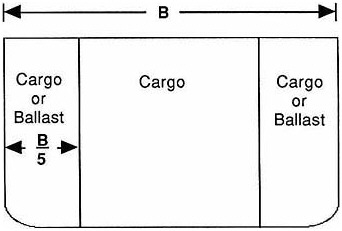
FIGURE 4-1 Transverse section of conventional MARPOL tanker.
must survive side penetration to a distance of B/5. Conventional MARPOL tankers usually carry the ballast in a series of wing tanks with a width of B/5. (See Figure 4-1.)
Neither minimum segregated ballast requirements nor damage-stability assumptions are altered for ships with double bottoms, double sides, or double hulls. The obvious design approach is to make use of the ship's required segregated ballast volume in arrangements that minimize additional impact on cargo capacity.
Double bottoms usually are set at a height of B/15 or more, except in the very large ships. The void space usually is used for ballast; there is no penalty in cargo capacity compared to other SBT designs. Actually, a B/15 inner bottom provides insufficient volume to satisfy segregated ballast requirements, so such designs require one or more pairs of side ballast tanks (fewer than a conventional MARPOL tanker).
For double sides, with a single-bottom cargo section, the B/5 width imposes a heavy penalty on cargo carrying capacity. The loss can be as much as 20 percent over and above the MARPOL segregated ballast requirement. Therefore, for double-side designs, tanks are sized to provide only the standard segregated ballast volume; the width of such side ballast tanks typically is B/9 to B/11. Of course, the designer must ensure that the ship has adequate stability to withstand collision damage extending into the inner tank, due to the B/5 penetration criteria. But this burden is far less onerous than losing more cargo capacity.
For double-hull designs, the height of the double bottom is usually B/15,
driven by the rule governing extent of vertical damage. The balance of the required segregated ballast, when distributed along the entire side, requires double sides with a width of about B/15 also (by coincidence). This arrangement results in little or no penalty in cargo carrying capacity compared to the MARPOL segregated ballast requirement.
A study of how various combinations of double bottoms, double sides, and double hulls affect cargo capacity (and stability) can be found in Appendix D. The study focuses on a generic 35,000 DWT tanker. Because B/15 for this 89-foot-wide ship is less than 2 meters, the rules require a minimum 2-meter double side. For ships of this size, designers often provide 2-meter double bottoms—or slightly more than B/15. Nonetheless, the double-bottom, double-side, and double-hull designs have comparable cargo capacity, essentially unchanged from the MARPOL design. (See Appendix D.)
A minimum spacing of about 2 meters between hulls should allow adequate access for inspection. For larger ships, where a B/15 double bottom is so high that inspection and maintenance become difficult, a designer might choose to limit the inner bottom to a height such as 3 meters. 4 This approach has the further advantage of offsetting any reduction in cargo carrying capacity, and/or creating additional side protection (to fulfill ballast requirements) without further impact on cargo capacity. Other designers might favor higher double bottoms, to assure that all structure, such as framing, can be kept within the double bottom (this usually is facilitated, on larger ships, by heights greater than 3 meters).
For smaller tankers, 40,000 DWT or less, accident data indicate that a B/15 double bottom is very effective in preventing outflow in groundings (Card, 1975). There is no such casualty database for larger double-bottom tankers. An outflow analysis conducted by Det norske Veritas (DnV) (Appendix F, Table 3.3.1) suggests that exceeding the B/15 double-bottom height provides diminishing incremental protection against outflow during groundings of larger tankers. On the other hand, for VLCCs and larger tankers, outflow protection against collisions continues to improve with increasing distance between sides. A B/15 double side offers protection against low-and medium-energy collisions, but increasing the space between the double sides enhances this protection.
The key factor in determining outflow, of course, is the relative frequency and severity of groundings and collisions in U.S. waters. In any event, from a pollution-control standpoint, the DnV data suggest that, for tankers larger than about 120,000 DWT, some of the SBT volume dedicated to B/15 double bottoms might be more profitably invested in wider double sides. More study is needed to determine the best proportions of SBTs in larger double-hull tankers. In the meantime, in the interests of both ease of inspection and maintenance and improved overall pollution control, inner bottom heights of less that B/15 may be appropriate for larger tankers.
Segregated Ballast Tank Arrangements
Figure 4-2 shows schematically various configurations of tanks in double sides, double bottoms, and double hulls. The "C" and "B" signify cargo and ballast tanks, respectively. Figure 4-2a is a double-bottom arrangement. Most ships without double sides will have three tanks across because of the B/5 penetration rule. Double-side ships, Figure 4-2b, can be more flexible in tank arrangement as long as stability remains sufficient with a penetrated cargo tank side.
Figure 4-2c is a common double-hull ("L" tank) arrangement; it has the disadvantage of potentially large off-center weights if damaged. The "U" tank arrangement, Figure 4-2d, avoids that problem but doubles the total added weight in most damage cases. "U" tanks also can have a large free surface, involving some complications when loading and discharging cargo.
The arrangements in Figures 4-2e and 4-2f reduce the amount of off-center and total added weight for most damage scenarios, by separating the side and bottom ballast tanks. Figure 4-2e is more resistant to grounding damage while Figure 4-2f is more resistant to collision damage. The former provides improved structural continuity of the double bottom. The disadvantages of these two "DB + DS" arrangements over the "L" or "U" tank arrangements are added cost, and complications of access and ventilating the double bottom. However, the complications are no greater than for the double-bottom design, Figure 4-2a.
The number of longitudinal bulkheads shown in the double-side and double-hull examples is not intended to be literal. The number of internal bulkheads (up to three for the largest tankers) is dictated primarily by cargo outflow limits, the number of petroleum grades to be carried, structural configurations (on very large tankers), and the free surface effects on stability. For tankers up to about 150,000 DWT, current criteria generally can be met with no internal longitudinal cargo tank bulkheads, i.e., a single cargo tank between wing bulkheads.
Actual tank arrangements, of course, are selected by owners and designers to best meet these requirements. The various alternatives should be studied to determine the best proportions for a given trade and the risks encountered in that trade.
The foregoing description addresses the more conventional design approaches to double bottoms, double sides, and double hulls. Another tank arrangement scheme receiving considerable attention is the intermediate oil-tight deck (IOTD), where the cargo section is divided by a deck or a flat, horizontal bulkhead, with oil carried in both upper and lower chambers. This is essentially a double bottom of great height, loaded with oil. Figure 4-3 is a schematic of such a design. In addition to reducing the volume of oil exposed to a bottom rupture, the lower section has initial hydrostatic advantages over conventional MARPOL single-hull tankers. Coupled with
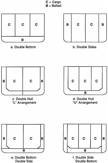
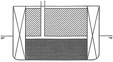
FIGURE 4-3 Schematic of intermediate oil-tight deck with double sides.
double sides, the IOTD also would provide protection against collisions. This concept will be evaluated in Chapter 5.
Stability of Double-Hull Tankers
A range of factors must be weighed in assessing double bottoms, double sides, and double hulls. These designs have operational and in some cases survivability advantages, but they also involve penalties in such areas as ease of inspection and maintenance, and possibly safety. A more comprehensive assessment of these designs may be found in Chapters 5 and 6. From an engineering perspective, however, all current stability criteria can be met, and exceeded, with properly subdivided B/15 double-hull designs.
All tankers must satisfy specified stability criteria to assure safe operation in heavy wind and sea conditions. They also must survive specified damage by meeting list,5 flooded waterline, and range-of-stability criteria. As noted earlier, two of the damage criteria are the extent of vertical and horizontal penetration (B/15 and B/5, respectively), which influence the placement of double bottoms and double sides; other criteria involve the length of structural damage and the number of adjacent compartments that can be flooded. The details are not critical to this report, other than the fact that tankers exceeding 492 feet in length (about 15,000 to 20,000 DWT) must be able to survive flooding of two adjacent compartments.
Conventional SBT tankers are very stable; in fact, most such tankers far exceed the minimum IMO damage-stability requirements. This is largely because tankers typically have empty side ballast tanks separated by one or
more loaded cargo tanks. When several cargo and ballast tanks are breached, the added off-center weight from flooded ballast tanks is in part compensated by the loss of weight due to oil flowing out of cargo tanks. By comparison, if a double-hull tanker incurs comparable hull penetration affecting only empty off-center SBTs, then there is no compensating loss of oil. The net increase in weight can be significantly more than for conventional tankers, and double-hull vessel damage stability, while meeting IMO standards, can be significantly less than for a conventional tanker. Thus, a double hull designed to meet current minimum damage stability criteria will not tolerate as much damage as a conventional MARPOL tanker—not because the former fails to meet damage stability requirements, but because the latter usually exceeds requirements.
Chevron Shipping Company has demonstrated these factors vividly. The company's report (abstracted in Appendix E) shows that the damage stability of an ''industry standard" single-hull 130,000 DWT tanker greatly exceeds present criteria (Figure E-4 in the Appendix). A comparable double-hull tanker, with interhull spacing of 2 meters and fully loaded, also easily exceeds criteria (Figure E-5) but can withstand less damage than the single-hull version. When 96 percent loaded with heavy crude, the 2-meter double-hull ship will capsize with only three tanks flooded. (The ship has "J" ballast tanks and no internal cargo tank bulkheads, and it meets current criteria.) But the report goes on to demonstrate that, with imagination, a double-hull tanker can be designed to survive flooding of ballast tanks along an entire side of the ship.
The Seaworthy Systems study (see Table 4-3 and Appendix D) demonstrates that small tankers with double sides, double bottoms, or double hulls also can be designed to exceed by a wide margin the current damage-stability requirements. The most desirable characteristics are small equilibrium heel, large righting arm, and large range of stability. The table shows that all the designs considered (even under severe damage scenarios) have adequate stability because they have equilibrium heel that is less than the range of stability, and because they all have positive righting arm. However, some results are less desirable than others. Some of the double-bottom and double-side cases have a greater equilibrium heel, and lower range of stability, than is present with the single-skin case.
The foregoing discussion suggests that the damage-stability requirements for double sides, double bottoms, and double hulls should be increased, to approximate the stability achieved by comparable single-hull MARPOL tankers.
SALVAGE CONCERNS RELATED TO SBT TANKERS
This section addresses the frequent claim that double bottoms handicap salvage, as well as other salvage-related matters involving cargo systems,
TABLE 4-3 35,000 DWT Tanker 4 Compartment Damaged Stability Worst Case Scenario
|
Alternative |
Damaged Scenario** (tanks damaged) |
Equilibrium Heel (degrees) |
Maximum Righting Arm (feet) |
Range of Stability (degrees) |
|
Single-Skin* (PL/SBT) |
Nos. 6, 7, 8, and 9 Stbd Cargo Tanks |
1 |
4.34 |
70 |
|
B/15 (2M) Double-Bottom |
Nos. 5, 6, 7, and 8 Stbd Double Bottom |
3 |
2.95 |
70 |
|
B/15 (2M) Double-Side |
Nos. 4, 5, 6, and 7 Stbd Wing Tanks |
6 |
3.26 |
70 |
|
B/15 (2M) Double-Hull |
Nos. 3, 4, 5, and 6 Stbd Wing Tanks |
7 |
9.50 |
70 |
|
B/5 Double-Bottom |
Nos. 3, 4, 5, and 6 Stbd Double Bottom |
13 |
0.40 |
17 |
|
B/5 Double-Side |
Nos. 3, 4, 5, and 6 Stbd Wing Tanks |
16 |
3.05 |
50 |
|
B/5 Double-Hull |
Nos. 3, 4, 5, and 6 Stbd Wing Tanks |
12 |
5.2 |
50 |
|
* No protectively located segregated ballast tanks were damaged to avoid running an inordinate number of damage conditions. ** The damage suffered is twice the current criteria (4 versus 2 adjacent tanks flooded). In summarizing the discussion of tank proportions, arrangements, and stability, this table (derived from Table D-2) is instructive. It shows the results of calculations of the effect of severe damage on a single-skin tanker and a combination of double-bottom, double-side, and double-hull tankers that are typical of designs that could in practice be built. The following definitions apply: • equilibrium heel is the angle of list (or tipping to the side) that the ship will have after damage has occurred. • maximum righting arm is a measure of the relative reserve capacity of the ship to return to the equilibrium heel angle after damage has occurred. • range of stability is the additional angle of heel the ship can accept and still return to the equilibrium position. When the range of stability is exceeded, the ship turns over. (For instance, the B/5 double-hull ship could roll to a total of 62 degrees and still return to its damaged equilibrium angle of 12 degrees). |
||||
emergency pumping capabilities, and on-board computers used to monitor loading.
Double Bottoms and Voids in Salvage
To examine the claim that double bottoms handicap salvage (and may increase oil outflow in a grounding), four types of grounding obstacles must be considered:
-
Type 1: The pinnacle. In this scenario, the ship strikes a relatively small rock or pinnacle that cuts into the hull. Depending on ship momentum and the extent of interference by the obstacle, the vessel may pass over the obstruction with damage ranging from minimal to a long, narrow tear opening several hull compartments. If the ship passes over the obstruction, then it remains floating; if not, it is "stranded."
-
Type 2: The rocky shoal. This obstruction, the big brother of the pinnacle, brings the ship to a halt. Damage will be extensive, although the longitudinal extent may not be as great as in the case of the pinnacle.
-
Type 3: The submerged reef. This obstacle is characterized by a smoother contour than the rocky shoal; it may be mud, sand, coral, or loose rubble, with deepwater on the far side. The ship may be brought to a standstill, or, if the interference is less than a foot or so (or the reef material is loose and moveable), then the ship may pass over the obstacle with little damage or flooding.
-
Type 4: The sloping beach. The water depth shoals continuously over a broad area. Depending on the bottom material and ship speed, a vessel hitting the beach may sustain damage ranging from scratched paint to extensive rupture and tearing. If speed were more than 2 or 3 knots, the ship would remain stranded.
Tides play a major role in groundings. A ship that grounds lightly at low tide may float off with the rising tide. A ship stranded at high tide invariably will need help to be refloated.
The geographical location of a grounding also can be critical. For example, if a ship grounds on a pinnacle in the open ocean or on a coastline exposed to waves and ocean swells, then these forces can cause ship motions that can result in additional damage, or even loss of the ship in bad weather.
If the hull is breached, then flooding of voids such as inner-bottom or side-ballast tanks will make the ship heavier, leaving it harder aground. This is the basis for arguments that double bottoms complicate salvage. On the other hand, breach of a single-hull tanker usually will spill oil, making the ship lighter. Thus, in a Type 1 or Type 3 grounding, a single-bottom tanker would be lightened and would rise and pass over the obstacle. Even in the Type 4 grounding, the argument continues, the single-bottom ship theoretically would be easier to refloat, perhaps by backing off on a rising tide.
At issue is the frequency of Type 1 and Type 3 groundings where single-hull tankers passed over the obstruction or were refloated easily. The committee was unable to obtain data to define the relative risks of encountering the four bottom types described. Although there are reports of a few ships passing over obstructions while spilling only a modest amount of oil, the statistics are insufficient to counter the committee's view that most tankers, grounding at service speeds (14 to 16 knots), will remain firmly stranded—with or without the reduced-weight advantage of lost cargo.
An important point here is the definition of salvage. For purposes of the present study, salvage means voluntary assistance by outside professionals to save a ship and cargo in peril; thus, actions by the ship's own crew do not constitute salvage. These in-house actions, called damage control, generally will be useful to the salvor, especially if they have prevented further damage. In any event, regardless of the frequency of strandings requiring outside assistance, professional salvors routinely encounter such situations. And salvors do not consider double bottoms a handicap, for reasons to be described shortly; rather, salvors view double bottoms as helpful.
Another dimension of the salvage controversy is the claim that double bottoms can increase the amount of oil spilled. This argument is refuted by physics. A double-bottom tanker will not normally carry cargo at a higher level than will a comparable single-hull SBT tanker. And because of the bottom void, which will fill with cargo if the inner bottom is punctured, the hydrostatic head6 of oil relative to the sea will be less than for a single-hull MARPOL tanker. Therefore, the outflow actually will be comparable, or even less, in a double-bottom tanker (the effect of hydrostatic pressure differentials was explained in Chapter 3).
The final claim to be considered here is that a stranded tanker with a flooded double bottom can be exposed to danger for an extended period of time, because of the increased off-loading required to refloat the casualty. During this added time, a sudden storm could interrupt the salvage operation and cause total loss of the ship and cargo. The single-hull tanker METULA, which was stranded in the Strait of Magellan in 1974, is offered as an example. Off-loading resources were limited, and, had the ship been fitted with a double bottom, an actual storm would have overwhelmed the ship before the required amount of cargo could have been off-loaded. However, the option of pumping some oil overboard (to prevent the sure spill of far more oil in the storm) would have been available. The possibility of losing the entire cargo from a stranded double-bottom tanker (where a single-bottom tanker would have survived) is remote.
In summary, there is insufficient evidence to refute the committee's opinion that the great majority of tanker groundings at service speeds will leave the tanker firmly stranded, and in need of significant outside salvage assistance whether or not the ship has a double bottom.
Salvage Procedures
To assess the impact of bottom and side voids on salvage, a basic understanding of salvage procedures is necessary.
Given a firmly grounded tanker, the task of the salvor is to determine as quickly as possible how, and when, to refloat the ship. The salvor considers not only tides, likely weather, and off-loading facilities, but also the extent of damage, hull strength, condition of propulsion and cargo systems, and
the ship's particular features that can either assist or hinder salvage efforts. The following steps invariably apply in salvage of a stranded tanker.
Stabilizing the Ship. This is the first step in salvage; it prevents the ship from broaching or being driven farther aground. This generally entails "making the ship heavy," which also prevents the ship from incurring additional damage in often-violent hull motions due to usual sea conditions. Stabilizing the ship requires quick action and intact tanks (some intact spaces invariably must be flooded). Flooded double bottoms will help; intact inner-bottom and side ballast tanks are excellent repositories for additional weight. Hull stresses in the grounded condition must be addressed carefully, and this generally is beyond ability of the crew.
Removing Oil Cargo from Damaged Tanks. Loaded tankers, when stranded, invariably require off-loading of a significant quantity of cargo. Usually this involves removal of large amounts of oil floating on top of seawater that has entered through the damaged bottom, as well as removal of oil from intact tanks to minimize the threat of additional pollution (should the ship break up before or after being refloated). Removal of cargo is usually time-consuming; other tankers, or barges and tugs, must be marshaled, and weather may delay cargo transfer. Portable pumps and hoses always are required, unless the ship's cargo system is intact and operable. Generally, cargo must be removed from some intact tanks to allow for proper distribution of load and hull stresses after refloating. Environmental concerns may require removal of all remaining cargo before refloating, although this may mean leaving the ship stranded for a longer time. During cargo removal, compensating weight in the form of seawater ballast must be added to keep the tanker stabilized.
Lightening by Removal of Water. With the required amount of cargo removed, and the ship firmly under control of tugs and/or anchors and cable, ballast is pumped quickly out of intact tanks and sea water is blown out of flooded tanks with compressed air. (Water can be pumped much faster than oil, and it usually can be pumped overboard. If the tank tops are intact, "blowing" water out with compressed air is even faster.)
Bottom and Side Voids in Salvage
From the preceding, it follows that bottom voids and narrow wing tanks (or a full double hull) are valuable in salvage operations for four reasons: (1) If flooded, they immediately make the ship heavier and assist in stabilizing the hull on the strand; (2) The bottom voids likely will have protected at least some of the cargo tanks, not only limiting cargo loss but also preserving those cargo tanks for easy cargo removal and/or ballasting; (3) Flooded bottom voids, and usually narrow wing tanks, are strong enough to permit
quick water removal by "blowing" with compressed air. (The deck over large cargo tanks is generally strong enough to withstand the pressure of blowing out only limited amounts of water.); and (4) Intact voids can be completely filled with ballast, and if necessary can be cleared relatively quickly, with submersible pumps, if the ballast system is inoperative.
The committee could not identify salvage-related concerns that should limit the use of properly designed double hulls.7
Cargo Systems
One factor influencing oil outflow in an accident, and subsequent salvage activity, is the tanker cargo system. There are two basic cargo system designs. The traditional system centers around pumps located in a pump room between the engine room and the last cargo tank. The complexity of the system is determined by the extent of cargo separation desired (to permit the carrying of different types of cargo). A variation on this system utilizes sluice values, through which cargo flows by gravity toward the rear tanks, where the cargo pumps take suction. This system is not suited to tankers carrying multiple cargo types (combinations of piping and sluice valves have been used on crude carriers for this purpose). Figure 4-4 shows conventional cargo system arrangements.
Segregation requirements led to development of a second type of cargo system based on deep-well or submersible pumps located in the tank bottoms. In many deep-well pump tankers, each tank has its own pump and there is no horizontal piping. Sometimes one pump serves either a pair of tanks via a sluice valve or several tanks through appropriate piping. Such piping is placed above the main bottom structure, but the length of the main runs is significantly shorter than for conventional systems. Figure 4-5 is a schematic of a deep-well cargo piping arrangement; this system eliminates the need for a pump room.
Tanker cargo systems can minimize or—if damaged—encourage oil outflow in an accident. Because key components are located close to or at the bottom, fairly modest hull damage can disrupt the system, not only for the tanks involved, but also for intact tanks. Valves can be jammed, pumps can be crushed, piping systems can be broken. Other effects of the accident might force shutdown of the ship's engineering plant, eliminating power for operating the cargo system. Such events have a significant impact on short-term loss of oil after a grounding, as well as on salvage of a stranded tanker, as noted previously.
Emergency Cargo Pumping Capability
Cargo systems are not now designed with the possibility of an accident in mind. Lightening the casualty, therefore, usually requires removing oil
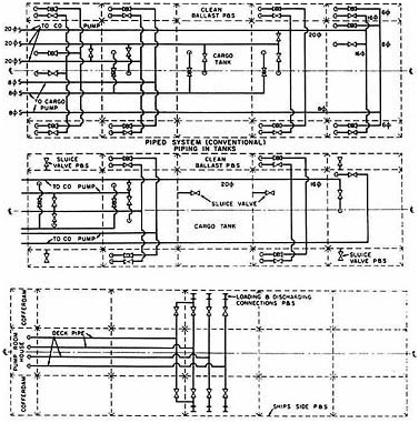
FIGURE 4-4 Conventional cargo systems. Source: Society of Naval Architects and Marine Engineers, 1980.
by portable pumps, always a slow and tedious process. Submersible pumps generally are used; their size and weight is limited by what can be airlifted and crew-handled, and can fit through a 12.5-inch "Butterworth" tank cleaning opening. (Some tanks fitted for crude oil washing may have no opening other than the main access, where ladders will interfere with pump placement.) Oil removal is particularly difficult in a punctured tank where the oil-water interface rises as oil is removed. The height of the pump may require frequent adjustment, especially as the tide rises and falls.
Cargo piping should not be located in a double bottom void. To do so risks cargo loss even when the inner bottom remains intact. Conversely, a properly located cargo piping system in a double-bottom tanker is less susceptible to damage than that in a single-bottom tanker.
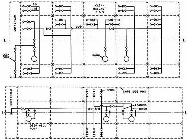
FIGURE 4-5 Deep-well cargo system. Source: Society of Naval Architects and Marine Engineers, 1980.
Another concern with conventional cargo systems is that once hydrostatic equilibrium is achieved, the cargo system, even if operable, will pump only water, once water reaches the suction level (assuming water flows in faster than oil can be pumped out). A separate system with alternate suction points, perhaps at quarter-tank height and at the level of the loaded water-line, would enable an otherwise intact cargo piping system to rapidly transfer or off-load cargo from breached tanks. In addition, improved (damage-resistant) details of cargo systems at suction points should ensure operability in the event of bottom distortion (short of rupture). Alternate pumping sources also would be useful if, for instance, the pump room were flooded or burned. Such capability would facilitate the transfer of cargo from a damaged tanker to another ship, or within a ship to intact empty tanks.
Salvage Calculations and Computer Programs
Computer use is universal in naval architecture. Besides enabling designers to produce "more efficient" structural designs, computers have facilitated studies on hydrostatics, stability, and damage stability. How-
ever, the predicted behavior of ships sustaining high-energy grounding damage sometimes has been significantly more pessimistic than that calculated by salvors.
This discrepancy arises because some computer programs calculate damaged stability assuming all cargo flows out of damaged tanks, to be replaced with seawater to the equilibrium water line. In fact, this methodology is required by IMO damage-stability criteria. While providing a conservative result for routine damage-stability studies for comparative design purposes, this method is inappropriate for tanker salvage scenarios involving major damage. It ignores the beneficial buoyancy of the oil remaining in the ship. In the case of the EXXON VALDEZ, for instance, the potential net buoyancy of the 42,500,000 gallons of oil remaining inside the hull was approximately 32,000 tons—or more than the 28,973-ton weight of the entire hull! Tankers seldom sink if the hull remains even reasonably intact. Witness the aircraft attacks on shipping in the Persian Gulf during the war between Iran and Iraq, where not one loaded tanker was sunk, and the more recent example of the MEGA BORG, which survived a major, week-long fire off Galveston, Texas, losing only about 10 percent of its cargo. Extreme care is required when using typical naval architecture computer programs in salvage operations and related analyses.
SAFETY OF LIFE
International resolutions related to ships traditionally have focused on safety of life, whether it be lifeboat requirements devised after the TITANIC catastrophe or load-line criteria resulting from losses of ships and entire crews due to overloading.
The committee's task was to evaluate alternate tanker designs intended to mitigate pollution from collisions and groundings. However, the accompanying risks of fire and explosion, and the personnel risks of operating and maintaining alternative tanker designs, cannot be ignored, any more than the pollution that could result from these hazards. This section addresses these aspects of alternative designs and their potential impact on the lives of the men and women who work on these ships.
Explosions and Fires
Segregated ballast tanks, mandated for new ships over 20,000 DWT, are by definition either empty or filled with seawater ballast. Particularly when empty, they are subject to rapid corrosion unless preventative measures are taken. Such methods include anodic protection, protective coatings, and possibly inerting (all described in Chapter 3). At least one wall of a segregated ballast tank is shared by a cargo tank. Any failure of this structure,
due to corrosion or cracking, can allow oil to leak into the ballast tank, creating a risk of explosion. Potential sources of oil vapors are multiplied if cargo piping is routed through segregated ballast tanks (though this is seldom done and can be proscribed).
The alternative tanker designs proposed most frequently involve double bottoms and/or double sides. These designs increase significantly the void areas adjacent to cargo tanks. Assuming the risk of leaks is proportionate to the bulkhead area of ballast tanks shared with cargo tanks, double bottoms and sides increase significantly the risk of encountering explosive atmospheres. This is a common argument against such designs.
Existing data cannot predict precisely the increased risk of personnel hazard and explosion posed by greater amounts of segregated ballast tankage. On the positive side, there is a growing fleet of SBT, double-bottom, and some double-hull tankers, some of which have been sailing for 20 years or more. As far as the committee can tell, these tankers have not had a greater problem with either personnel casualties or fires/explosions than conventional pre-MARPOL single-hull tankers. However, this is not to say that the safety problem of additional void spaces can be ignored. Crew training will continue to be vital, along with careful design, inspection, and maintenance.
SUMMARY
This chapter has made a number of points that will figure in the forthcoming assessment of alternative tank vessel designs. Also worth noting are several findings that will contribute to the committee's overall recommendations for reducing pollution risk.
In general, modern tankers are proportionally less robust than their predecessors; this trend could be reversed through modification of classification society rules. To their credit, classification societies have commenced evaluation of these rules. More research should be done on the proper use of high-tensile steels in tanker construction. More research also is needed to improve resistance of tanker structure to collision and grounding damage, and to enhance residual strength following major damage.
In tanker design, the aims of pollution prevention, stability, strength, salvage, safety, inspection, and maintenance can be conflicting. However, from an engineering standpoint, all these interests can be satisfied in design of double bottoms, double sides, and double hulls, relying on present technological capabilities. All current stability requirements can be met, and exceeded, with properly subdivided B/15 double-hull designs. Furthermore, these designs generally enhance salvage. And, given the extra maintenance and inspection warranted by the increased void space, vessels with double bottoms/sides can be operated safely over a vessel's normal lifetime.
Consideration should be given to increasing the damage-stability require-
ments for double-hull tankers, to approximate the stability actually achieved by comparable single-hull MARPOL tankers. The proportions of double hulls also deserve further study, to optimally satisfy all interests including pollution control, stability, maintenance, safety, and cost. In addition, the outer shell of double-bottom, double-side, and double-hull ships should be no more vulnerable to penetration than conventional single-hull MARPOL tankers.
In ships with double bottoms and/or double sides, cargo piping systems should be kept out of the voids, to improve damage resistance and to reduce risk of oil leakage and explosion. Pollution control also could be enhanced through modifications to conventional cargo systems to facilitate the pumping of cargo from a damaged tank to other tanks or another ship. Alternate pumping sources for cargo systems also should be explored.
NOTES
|
1. |
Heel is the extent of a vessel's incline or tilt to one side; trim is the position of a vessel with reference to the horizontal, or the difference in draft forward and aft. |
|
2. |
Hull bending moment is the summation of the weight, buoyancy, and dynamic forces that tend to bend the hull. |
|
3. |
Tank width (and therefore bulkhead spacing) is affected by cargo outflow limits and by the "free surface" effect. The latter refers to the free movement of liquid in a partially filled tank; this has a significant negative impact on transverse stability. The effect is proportional to the cube of the tank width (w3). Adding longitudinal bulkheads can improve stability significantly. For instance, the potential free surface impact of one 60-foot-wide tank is four times that of two 30-foot-wide tanks of the same length. |
|
4. |
A recent Japanese study (Ministry of Transport, Japan, 1990) examines various large hull designs, several of which have inner bottom heights of less than B/15. Chevron Shipping Company (see Appendix E), an experienced operator of double-hull tankers, likewise promotes double sides/bottoms of B/15, but not less than 2 meters and not required to be much more than 3 meters. |
|
5. |
A ship's tilt to one side in a state of equilibrium (as from unbalanced loading). |
|
6. |
Pressure at the bottom of the loaded cargo tank. |
|
7. |
Responses to an informal survey of salvors were unanimously in favor of double bottoms. |
REFERENCES
Card, J. C. 1975. Effectiveness of Double Bottoms in Preventing Oil Outflow from Bottom Damage Incidents. Marine Technology 12(1):60-64.
Chevron Shipping Company. 1990. Double Hull Tanker Design. Paper prepared for Society of Naval Architects and Marine Engineers convention, sent to Committee on Tank Vessel Design, NRC, Washington, D.C., October 1990.
Exxon Corp. 1982. Large Tanker Structural Survey Experience. Paper published by Exxon, New York.
Ferguson, J.M. 1990. Structural Integrity and Life Expectancy. Paper published by Lloyd's Register of Shipping, London.
Iarossi, F. (president, American Bureau of Shipping). 1990. Getting Ready for a Shortening Life. Fairplay International September 20:37.
International Association of Independent Tanker Owners. 1990b. Quest for the Environmental Ship. Draft of paper to be published by the Association, Oslo, Norway.
Liu, D. 1990. Letter to the Committee on Tank Vessel Design, NRC, Washington, D.C., May 10, 1990.
Ministry of Transport, Japan. 1990. Prevention of Oil Pollution. Report prepared for IMO Marine Environment Protection Committee, received by Committee on Tank Vessel Design, NRC, Washington, D.C., November 1990. Tokyo.
Royal Institute of Naval Architects. 1990. The Naval Architect. September:E357, E381, E385.
Society of Naval Architects and Marine Engineers. 1980. Ship Design and Construction. New York: SNAME.
U.S. Coast Guard. 1990c. Report on the Trans-Alaska Pipeline Service (TAPS): Tanker Structural Failure Study (draft). Washington, D.C.: U.S. Department of Transportation.


