
4
Shiphandling Simulators
Shiphandling simulators encompass a wide range of capabilities, facilities, and man-machine interfaces. They can be divided into two major classifications: real-time simulators, which have a human controller (referred to as a man-in-the-loop), and fast-time simulators, in which the human is replaced by a computer-based pilot model (often referred to as an autopilot). Because there is no human involved in fast-time simulation, the speed of the simulation is limited only by the speed of the host computer. With modern computers, these simulations can be performed at much greater speed than real time.
Simulation allows examination of proposed waterway designs before they are selected or implemented. The primary contribution of simulation is quantitative performance data characterizing the design and operational alternatives being considered. A number of methods furnish data that can be used in the design process: physical models, fast-time mathematical models, and man-in-the-loop simulation. The latter provides data on the entire navigational system, including the variability of the shiphandler, and thus it is referred to as full-mission simulation. This method provides subjective evaluations as well as quantitative assessments that can be used to guide the selection process and acceptance of a proposed design.
Both fast-time and real-time simulations are available offering various levels of sophistication. The phenomenal growth in computing power and its low-cost availability relative to the total cost of a simulator program has
eliminated simulator hardware as an important limiting factor in applying simulation to waterway design. Instead, the cost of obtaining data for the mathematical models (called identifying the model), processing of these data, and developing the visual scene are emerging as the dominant costs in marine simulation.
COMPUTER-BASED MODEL FOR SHIP BEHAVIOR
A simulation model for ship behavior is a computer-resident mathematical model of the waterway and of the dynamic properties of the ship. The waterway model includes not only the bottom topography, but also the winds and the currents below the water surface. This model is usually a combined data base and interpolation scheme where model details can be determined for an arbitrary location in the waterway.
The core of the ship dynamic model is the set of equations of motion of a rigid body (the flexibility of the ship is inconsequential for these problems). The equations of motion are usually referred to a coordinate system fixed in the ship, and the result is called Euler's equations of motion. These equations are six-coupled, nonlinear, ordinary differential equations that relate the motions of the ship to arbitrary external forces acting on the ship.
The force system that acts on the ship is a result of hydrostatics, hydrodynamics, and aerodynamics. Hydrostatic forces can be computed by Archimedes' principle. Techniques for numerically modelling the exact flow of air or water around a ship hull do not exist, even in the open ocean where the topography of either land or ocean bottom is not an influence. In a waterway, these local topographical details are very important and strongly influence the hydrodynamic and aerodynamic forces acting on the ship. As a result, a combination of theory, experimental results, and heuristic approximations is used to determine mathematical expressions for the force system on a ship in a waterway.
In addition to the ship's dynamics, mathematical models are developed for several other dynamical systems. These include the main propulsion system; steering machinery; thruster machinery, if available; and assistance of tugboats.
The success of the computer model in reproducing a vessel's behavior depends on the ability to describe the waterway and its environment numerically, to predict the instantaneous force system on the ship, and to integrate the mathematical expressions or algorithms of the ship and other mechanical components that contribute to the vessel's trajectory. Each of these elements involves approximations, and in the end, each is reduced to a set of equations. A detailed discussion of this process is given in Chapter 5.
In recent years, digital computers have been used exclusively for these problems. Inputs to the simulator computer are the commands issued by the
pilot, and output is the position and velocity of the ship and the visual presentation. Because the size (and cost) of modern digital computers of high capability is so low, the limitations on speed and memory capacity that were important considerations 20 years ago no longer exist. Therefore, the quality of the module for the vessel's behavior rests solely on the expressions, algorithms, and data bases that are programmed into the computer. In practice, these algorithms, hull and model scale data, and expressions are usually proprietary to the individual simulation facility, and as a result, comparisons of these aspects among facilities are limited.
Specific Components of Fast-Time Simulations
Fast-time simulation is closed loop, with a pilot model rather than an actual pilot in the loop. The pilot model, or autopilot, is computer software that simulates, to some level, the human performance of a shiphandler. It is not to be confused with the autopilot hardware found aboard ships that steers set courses or predefined turns. Pilot model software provides dynamic access to the necessary vessel motion and waterway data base parameters and algorithms to evaluate the vessel's track and to generate appropriate control commands for the vessel.
The typical autopilot for fast-time simulation is part of the software in the computer-based simulation and is defined in terms of the algorithms it uses to evaluate the vessel's track and to generate control commands. In typical fast-time simulation, the simulator operator supplies additional information in the form of a preferred track for a point on the ship (usually at midships centerline). The track may also include desired speeds for various parts of the transit that are used to trigger engine commands. This track therefore represents a predetermined strategy for negotiating the passage and is presumably geometrically feasible (that is, if the ship follows the path exactly, no portion of the ship should extend beyond the bounds of the waterway). The pilot model in this situation performs as a track follower, because this approach roughly approximates what happens when a human pilot starts a passage with a set strategy and adjusts the transit when deviations from the planned route occur. In practice, the programmed track for the pilot model is usually selected after consultation with experienced pilots about appropriate transit strategies.
Autopilot designs can vary in sophistication depending on their needs. At one end of the spectrum, a simple autopilot is used. This autopilot, using the exact location of the ship (as computed by the mathematical model) as datum, generates simple rudder and engine commands as specified by the associated transit strategy in an attempt to minimize any deviation between the current location and the prescribed track.
The simulation obtained by simple pilot models are useful because dynamically feasible swept paths can be defined. For example, results can
include deviations from the desired path resulting from such factors as inertia of the vessel, hydrodynamic effects, and lags in the power plant and steering gear.
Attempts are often made to make the pilot model behave more like a real pilot, including one or more of the following refinements:
-
making the position error zero until a certain detection threshold is met,
-
not executing a command until it is a significant one (for instance, waiting until a rudder command of at least 5° or 10° can be given),
-
providing for anticipated course changes,
-
introducing delays in decision making, and
-
introducing noise (random error) into the position information.
Each refinement generally leads to a different swept path, which is in theory reflective of the swept paths that would be experienced with human pilots whose performance varies due to many factors such as professional skills, experience, and stress (including fatigue, boredom, and other physical condition factors). A virtue of the pilot model is that its performance can be made consistent (that is, human variations are screened out) so that the actual effects of physical forces on the design vessel for various tracks can be assessed through sensitivity analysis. Data from each approach can also provide a comparative basis for accommodating operational factors in the design.
Although the measures for representing human behavior introduce some variability into the pilot model, they do not achieve any semblance of the full complexity of human pilot behavior that reflects many different styles and levels of effectiveness in shiphandling. To represent the underlying perceptual and cognitive processes involved in detecting and interpreting aids to navigation and vessel traffic, decisions about maneuvering actions, and other operational decisions, much more sophisticated pilot models than exist today would be needed. Only then could true transit strategies be programmed into the simulation without taking the vessel into some predefined track. Potentially, developments in piloting expert systems (that is, computer-aided, knowledge-based decision making including use of neural networks) could be incorporated into pilot models to reproduce some of the more cognitive aspects of piloting behavior (Grabowski, 1989).
Fast-time simulations are usually used for sensitivity analyses because they do have consistency. One typical use is determining the effects of current variations and tidal stages on maneuvering. Because many runs can be performed in a reasonably short time, many different hydraulic conditions can be used. Another use of fast-time simulators is to evaluate a select number of alternate waterway designs. In either case, detailed records of the commands and resulting trajectories must be kept for analysis. This record-keeping requirement applies to real-time simulations as well.
Specific Components of Real-Time Simulators
Real-time simulation involves a number of large and often expensive physical components that are not used in fast-time simulation. These simulations must be run in real time because they involve the participation of the human pilot to interpret the progress of the transit and to issue commands. Paths of communication must be provided between the pilot and the computer, including a means of displaying the location of the ship to the pilot (visual display) and a means of communicating pilot commands to the computer (controls).
Visual presentation
Two different types of visual presentation of the vessel's situation in the waterway are common. One corresponds to a bird'-eye (plan) view, such as a radar screen; the other corresponds to a bridge-view display that resembles what the pilot might see looking out from the vessel's bridge. Of the two display systems, the bird's-eye view is by far the simpler one to develop and requires only modest computational capacity. The bird's-eye or situation display is often more detailed than the corresponding radar scene and may include an accurate depiction of the vessel, geographical landmarks, aids to navigation, and other waterway features. Simulation of the corresponding radar image can be effected by eliminating or reducing much of this detail. When coupled with information equivalent to what would normally be available on the vessel being simulated, this display can create a simulated operating environment corresponding to restricted visibility atmospheric conditions. Regardless of the display format, research has determined that if a simulation system provides more information to the pilot than available in real operating scenarios, the results of simulation may not be representative or useful (Norrbin, 1972). The results can also be biased if important information is missing.
Bridge-view displays are intended to be viewed and interpreted by the pilot as a representation of what would be seen during vessel transits when the atmosphere does not completely obscure the view of landmarks and aids to navigation. This display could simply be one monitor (corresponding to what might be seen out of one bridge window) or an array of screens presenting the pilot with a rendering of an actual 180° or a full 360° view. When using these displays, the following interdependent physical factors limit perceived realism:
-
display size,
-
physical field of view,
-
viewing distance (from the eye), and
-
display quality (for example, color resolution, spatial resolution, brightness, and contrast ratio).
Bridge-view and bird's-eye displays are usually computer generated and are presented using either cathode-ray tube (CRT) monitors or large-screen, television-like projectors. When projection systems are used, the display size can be made fairly large with increased eye-to-screen distance for realism. However, the resolution does not improve, and the brightness decreases in inverse proportion to the area of the display. A compromise between brightness, screen size, resolution, and eye-to-screen distance can be made to present reasonable visual cues to the pilot.
The physical field of view refers to the angle subtended by the display as seen by the person performing as pilot during the simulation. Usually this angle is measured in the horizontal (azimuth) plane for ship maneuvering problems. A small television-size monitor can have a large field of view if it is placed close to the observer. However, viewing such displays can be uncomfortable, and they do not impart the feeling of a view from the vessel's bridge or pilothouse due to eye-to-screen distance. For realism, it is important that the field of view being represented in the simulation scene be approximately matched by the observer's field of view of the simulation display. Both the observer's and the simulation scene's fields of view from a single monitor or projector are inherently limited. Large display systems are often composed of three, five, or more display screens arrayed in roughly a circle around a mock-up of the bridge. Coordinating the projectors for multiple displays is not difficult with today's technology; it is possible to obtain displays with up to 360° of azimuthal field of view, although a somewhat smaller field of view, about 240°, is more common. Vertical fields of view vary depending on the simulator application, 20° to 24° being typical. Docking simulators generally require a larger vertical field than those applied to maneuvering or channel design work. Reasonable depth perception and reduction of parallax error for the simulation scene in relation to a simulator's bridge typically require a screen-to-eye distance greater than 10 feet. The closer this distance is to real-life conditions, the smaller the parallax error.
Display quality can be measured by a number of factors, including resolution, update rate, and texture. Spatial resolution refers to the fineness of detail that can be displayed. For computer-generated displays, the smallest unit of display is called a pixel. Individual computer displays are generally rated by the two dimensions of the array of pixels forming the display. However, what is more important for a simulator display is the visual angle a pixel subtends for a pilot located on the simulator's bridge relative to the angular visual acuity of the pilot's eye. Depending on the sophistication of the computer display generation, the appearance of any pixel can be chosen
from a limited number of colors or greys, or from millions of different colors to reproduce natural shading and texture.
Update rate is the frequency with which new scene information is displayed. A slow update rate makes the scene ''jump,'' whereas a fast update rate (greater than 15 hertz) yields a movie-like smoothness of motion. This rate depends critically on the computer supplying the graphical information and is often significantly slower than the refresh rate, the rate at which the screen is "repainted" by the electronics. Higher refresh rates eliminate screen "flicker" which contributes to viewer fatigue. The computer determines what is displayed by computing a two-dimensional perspective view of the scene as observed from the pilot's station. The computer derives this view from a three-dimensional description of the modeled environment stored in its memory. The speed of the process depends on the computer's ability to form the elemental shapes comprising its two-dimensional picture, to eliminate hidden lines or surfaces, and to determine the color of each pixel. Special, dedicated computer systems have been developed to perform this type of calculation with great efficiency. Because the update rate varies inversely with the number and type of objects arrayed in the three-dimensional space that will be visible or bounded within the scene, simple scenes can be updated at a faster rate than complicated scenes.
An elemental shape formed in the perspective view (e.g., a polygon representing a buoy) can be filled uniformly with the same color or filled with different colors which form a pattern reflecting its "texture" or shading (where, for example, the smooth texture and shading of a buoy may differ from that of the surrounding water surface). Many newer graphical computers have the capability to produce such texture, which can contribute significantly to the apparent realism of the display. A special use of texture is the "greying" of distant objects to enhance the observer's feeling of distance.
Controls
Another aspect of the physical setup of a real-time simulator is the realism of the controls and the navigation instruments used in the mocked-up ship's bridge. There is a wide range of mock-up realism in common use for simulators. In the most modest facilities, the only display may be a single CRT monitor for radar and visuals; the controls may be simply "radio" knobs that can be turned to give commands to the engines or rudders; and the navigational instrumentation readout may be simply a printer or portion of the CRT that shows the current readings. In the most elaborate facilities, the complete bridge of a ship is duplicated including all standard, commercial instrumentation and controls. The equipment, furnishings, and bridge windows are arranged to conform to traditional bridge layouts or
layouts specific to the design vessel under study. Some facilities mount the bridge on a motion platform and include loudspeakers. The objective is to enhance the fidelity of the simulation by providing an approximation of the sound and feel associated with vessel response to environmental factors (for example, pitch and roll in a seaway) and maneuvering commands.
Fidelity
The word fidelity in this report refers particularly to the appearance and functionality of the simulator as experienced by the pilot. In the literature, the concept of fidelity often includes separate measures for various other components of simulation (for example, the mathematical model).
Ideally, the pilots are provided an environment that so closely resembles a ship's bridge (or pilothouse) that they are unable to detect that they are not aboard ship. In other words, the ideal is a bridge that looks, smells, feels, moves, and sounds like a real ship's bridge and has views through the windows and ports that are absolutely lifelike. Such an environment would be referred to as having "perfect" fidelity. These environments are, in fact, almost achieved for the training of aircraft pilots. The quality of the display and the realism of the mock-up contributing to fidelity are directly related to their costs, although the costs of the display hardware have dropped dramatically with advances in computer technology.
The actual environment presented to pilots in a simulator inevitably falls short of perfect fidelity, varying considerably from facility to facility. Most simulator facilities attempt to include appropriate displays that either mimic those on board an actual ship or at least evoke their presence. Some simulators incorporate the angular motions resulting from seaway and maneuvering by tilting the bridge and display systems. These motion systems can be extremely costly. Although one might naturally assume that higher fidelity is better, evidence is lacking that correlates the influence of fidelity to the results of the simulation. Consequently, no consensus exists among simulation practitioners regarding what levels of fidelity are required to achieve reliable simulation outcomes, or how the requirement might vary with the simulation study objectives.
There is considerable interest in the potential of technical representations such as electronic charts and real-time positioning displays to substantially augment and perhaps become more important than visual observations. A large number of performance and application issues are being researched, including the effectiveness of integrated displays for use in piloting waters (Astle and van Opstal, 1990; Clarke, 1990; DeLoach, 1990; Eaton et al., 1990; Grabowski, 1989; Graham, 1990; Kristiansen et al., 1989; Maconachie, 1990; Russell, 1987; Sandvik, 1990). However, there
are many national and international policy issues requiring resolution. Thus, adoption of advanced systems cannot be reliably forecast.
The eventual use of integrated bridge displays and the subsequent changes these may have on piloting, will need to be reflected in future real-time simulations. Since it is less expensive to emulate a high technology bridge than to produce a high fidelity visual scene, it is likely that the cost of these changes would not become an issue. For waterway design, it would be prudent to equip real-time simulators with display systems of appropriate fidelity and bridge equipment that reflect the probable state of practice for merchant shipping. Improved performance by ships with advanced positioning and control systems could be expected to provide additional margins of safety relative to simulation results.
Man-in-the-loop
Pilots as shiphandlers represent the most complicated element in the behavior of ship maneuvering through a waterway (see Figure 3.1). Pilots must integrate diverse information acquired via the human senses on all aspects of own ship, environment, and other vessel traffic, as well as navigational conventions and other factors (Armstrong, 1980; Crenshaw, 1975; Plummer, 1966). Because pilots are integral to shiphandling in confined waterways, inclusion of pilots with knowledge of the design vessel, local conditions, and tug assistance is essential to the simulation process, if the simulation is to have complete credibility with prospective users of the waterway.
The pilot views the waterway scene from the bridge directly or, especially in the case of obscured vision, through electronic means including VHF communications, radar, and electronic aids to navigation. The pilot gains immediate information about the vessel from the readouts of the vessel control instruments. Based on the pilot's experience on the waterway and interpretation of the situation, rudder and engine commands are given. The pilot's skill involves the ability to determine the vessel's position and motion within the waterway based on observation, to predict change in the vessel's track resulting from the local environment, and to initiate required maneuvering commands in anticipation of the vessel's progress so that it will remain on the desired track.
Selecting appropriate pilots to participate in a simulation involves considerations of piloting skills, local waterway operating practices, and statistical sampling factors. Even when pilots for a simulation study are selected as a representative sample of the local pool of pilots, significant variability among pilots and their piloting performance is inevitable. Piloting different types and sizes of ships in waterways is a skill that takes many years to learn. Piloting skills vary with the nature of service (that is, coastal, bar,
river, harbor, or docking pilotage, or a combination of pilotage services), experience, and personal capabilities. Also, a pilot's skill level may vary from day to day depending on human and external factors.
Piloting in a shiphandling simulation is somewhat different from real piloting. During the design stage of either a new waterway or an extensive modification of an existing waterway, no pilots have had experience with the design. The generic skills required to pilot a simulated ship through the waterway are, however, identical to those required if the waterway design is executed. Thus, it appears sufficient to use capable pilots for real-time simulation, with the understanding that these pilots will probably need to become familiar through simulation with the new or modified waterway. It is equally important that these pilots are familiar with the local operating environment and incorporate local knowledge into the simulation. Often, this can be assured by using pilots certified by the Coast Guard or appropriate state or local authority for the pilotage route.
If simulation runs are performed by pilots whose ability far exceeds the expected average for the waterway under examination, the results of the simulation may be overly optimistic. The converse may apply for simulations run with very capable pilots who lack the knowledge of local conditions. The fact that pilots know they are only performing a simulation and that the consequences of failure will not include vessel damage, lawsuits, or personal injury, may make their performance quite different from real-life pilotage.
Some simulator facilities always use a few select pilots in rotation. In these circumstances, peer pressure to excel and the simulator's sophistication may affect performance. This may be an advantage for simulation training but not for waterway design where duplication of real life performance is needed. Because there are no universally accepted measures of piloting skill or knowledge, assessment of these dimensions is subjective. It is difficult to evaluate whether or not pilots chosen to participate in a given simulation reflect the average capabilities of local pilots or how their performance may have been affected by simulation conditions or the pilots' sophistication with simulation techniques.
LEVEL OF SIMULATION
Each simulation facility conducting port and waterway design work uses different simulator components. These facilities are often compared by characterizing their components using a subjective measure called the level of simulation.
To indicate how this subjective measure might be arrived at, Figure 4-1 shows the various components that make up a real-time simulator and further subdivides these into the characteristics of the components. A profile
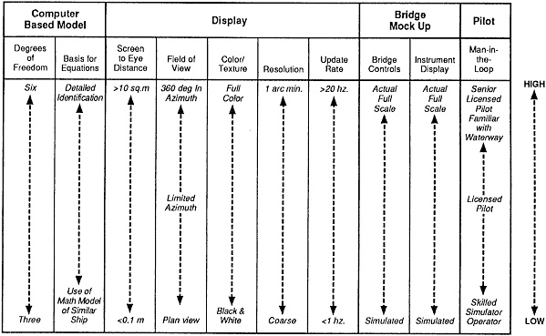
FIGURE 4-1 Levels of shiphandling simulation for evaluating real-time simulation facilities. Each column represents a scale for an individual characteristic of the simulation facility. The most desirable characteristics are at the top of each column, and characteristics of decreasing complexity (and generally decreasing cost) are listed down each column.
of any facility can be made by placing a horizontal mark in the figure at a height for each component that approximately reflects that facility. If the marks generally lie near the bottom of the columns, the facility is referred to as having a low level of simulation; if the characteristics generally lie near the top of the columns, the facility is referred to as offering a high level of simulation.
Practitioners of simulation generally accept that various levels of simulation are appropriate for different design situations. No definitive guidance is available to assist prospective users in determining the level of simulation needed for a particular problem. There is a dearth of quantitative information relative to selecting the level of simulation appropriate to a particular waterway design study. Nevertheless, if the level of simulation is not sufficient to capture an essential feature of the waterway, ship dynamics, or other key aspect of the real system, then the results of the simulation may be suspect. In practice, a higher level of simulation than what appears necessary is often used simply because the consequences of overlooking some subtle feature may have an important impact on vessel transit results. For example, the presence of a full bridge team to provide navigational support to the pilot would add to the face (that is, apparent) validity but would not necessarily add to the level of simulation. The actual contribution would depend on the capability of the bridge team to assess the operational situation and communicate this effectively. Thus, as with waterway design generally, the tendency in simulation is toward conservatism.
After the vessel (or vessels), environmental conditions, and appropriate simulator hardware are selected and installed, the simulation process occurs in three steps. In the preliminary phase, mathematical models of each simulation component are collected, and the various constants are identified (see Chapter 5). In the simulation phase, the model is exercised in either real time, fast time, or both. In the interpretation phase, the simulation results are assessed in terms of the risks posed by the channel design and potential alternative designs. However, because the simulation program is biased toward the most accident-prone situations, results must be carefully interpreted (see Chapter 6).
SUMMARY
The prospective user of shiphandling simulators for waterway design is confronted by several factors that complicate the decision to use a simulator. Given the range of technical considerations, careful examination of the capabilities, research methodologies, and results of available simulations is needed to assess simulator suitability for each individual waterway design project. Of equal importance is the selection of pilots for real-time simulations because they are critical to both the validity and credibility of results.


