
A New Way of Simulating Whale Tail Propulsion
J.van Manen (Whale Tail Development, The Netherlands), T.van Terwisga (Maritime Research Institute, The Netherlands)
1.
INTRODUCTION
Up to the Seventies of the Twentieth Century, the conventional screw propeller has shown a supremacy among the modes of ship propulsion. During the last decades some hesitation has appeared in the domination of this screw propeller by the development of “special purpose” ship types. Especially the development of wide, shallow-draft ship types causes restrictions in the maintenance of optimal efficiencies of the screw propeller.
Today, advanced ships demand a well-balanced compromise between the main requirements for a ship propeller, such as: high efficiency, minimum danger of cavitation, noise and erosion, minimum propeller excited vibratory forces, good stopping abilities and manoeuvrability, minimum vulnerability and low initial and maintenance costs.
During the last decades the non-conventional propulsion devices have shown to be competitive to the screw propeller. Especially the ducted propellers, the contra-rotating propellers and the waterjet propulsors have shown remarkable positive results. In the last years, the growing interest into fish, whale and dolphin propulsion is remarkable.
In 1963 for the first time systematic tests have been carried out with a group of vertical axis, “cycloidal” propellers, having an eccentricity of “e” >1, referred to as “trochoidal” propellers. The blade motion of the “trochoidal” propeller is quite reminiscent of the movement of a fish (Fig.1). These vertical axis propellers belonged to an unknown area of ship propulsion. The test results showed promising high efficiencies at high speeds and light propeller loading.
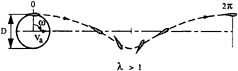
Fig. 1 Trochoidal blade trajectory.
At that time there was not sufficient interest for this extremely high speed area for ships. Nowadays the interest for ship propulsion for wide, shallow draft ship types is growing. The efficiencies of the screw propeller for these ship forms are by far not optimal, caused by the restrictions of the screw diameter and the propeller rotation rate. In fact for these ships only a wide, shallow draft rectangle is available for ship propulsion.
The break-through idea, thirty years after the first systematic tests with the vertical axis “trochoidal” propellers is the development of these propellers with a horizontal axis. The “trochoidal” propeller with a horizontal axis is mounted in the hull's afterbody over a large part of its width. The propeller is further characterized by a relatively large span of the blades, which are clenched on both ends of the blades. These end connections
enforce a specified blade angle as a function of blade orbit position. Intermediate supports distributed over the span are applied where necessary to ensure sufficient stiffness of the blades (see Fig.2).
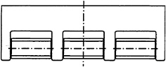
Fig. 2 Stern view of an aftbody with Whale Tail Wheel propulsion.
The allowable large area of the propeller and the almost two-dimensional flow about the blades give it an unequalled high performance potential for the requirements of many ship types. The large area of the propeller is expressed in a low thrust loading per unit envelope area. This allows the required change in momentum of the flow to be obtained by a relatively small acceleration of fluid. A corresponding high ideal efficiency is obtained. The trochoidal propeller with a horizontal axis, ‘Whale Tail Wheel' in the following, is a combination of the tail propulsion of a living creature and the wheel, invented by mankind.
The choice of the dimensions of the Whale Tail Wheel can lead to a minimum thrust loading per unit envelope area and consequently to the optimum of the maximal efficiency curve of the trochoidal propeller with a horizontal axis. A shape of afterbody adapted to the two-dimensional character of the lightly loaded Whale Tail Wheel will realise promising conditions for the control of cavitation and vibration risks.
2.
HISTORY
A summary of the historic review by Brockett (1) is presented here:
‘Different configurations of the cycloidal propulsor were independently developed by Kirsten (2), (3) and Schneider (4) during or prior to the 1920's. The blade angle control of Kirsten is fixed by gears and has experienced only limited development. The more complex but controllable blade angle orientation using linkages proposed by Schneider has received considerable development.
There are two traditional regions of pitch control. One for low-pitch propellers (associated with orbit circumferential velocities ωD/2 greater than the advance speed V0), and one for high-pitch propellers (associated with circumferential velocities less than the advance speed). Low speed manoeuvring requirements have led to extensive development of the low pitch configuration (Schneider (4)). Such propellers have top speeds usually less than 20 knots. High pitch propellers have hydrodynamic efficiency values greater than for low pitch propellers and permit high speed operation. These latter propellers have to date however, received most attention at only research level (e.g. van Manen (5)).
A survey of cycloidal propulsion has been given by Henry (6). He presents a history and a description of some kinematics of the motion of a cycloidal propeller, as well as a critical review of early attempts to model the flow field. Some of his suggestions for improved modelling have yet to be implemented. Improvements in performance were addressed by Sparenberg (7), (8) and James (9), who attempt to define blade angle control specifications for improved efficiency based on two-dimensional flow models.
Systematic series data are presented by Nakonechny (10), (11), Van Manen (5), Ficken (12) (who includes Nakonechny's data in his faired curves), Bjarne (13) (see also Kallstrom and Loid (14)), and Bose and Lai (15). The most extensive of these series are those of Van Manen and Ficken. The main variable in these investigations is pitch control, but several blade shapes are also evaluated. Van Manen includes evaluation of the blade angle motions derived by Sparenberg (7), which did produce improvements in efficiency over his conventional cycloidal blade angle variations.
Van Manen's experiments (with low pitch propellers) produced generally lower efficiency values than expected, which has been partially explained by Ruys (16) as a viscous effect. Van Manen's data for high-pitch propellers had quite respectable efficiency values (η0~0.7).' (Brockett (1)).
3.
WORKING PRINCIPLE
Propulsion fundamentals
The general principle underlying the thrust production of any propeller is strongly summarized in the conservation law of momentum. A conse
quence of this physical law is, that an action force is required to accelerate a certain amount of fluid. This action force is exerted on the fluid by an actuator. The actuator often consists of a conventional propeller. But it may also consist of a paddle wheel or a cycloidal propeller with either a vertical shaft (e.g. Voith Schneider propeller) or a horizontal shaft (Whale Tail Wheel).
In an ideal non-viscous flow, the acceleration of the flow through the actuator, not only creates a reaction force of the flow on the actuator (thrust), but also causes an energy loss. This energy loss is manifest through the kinetic energy in the wake of the propulsor. The energy loss is the difference between the added kinetic energy to the wake, and the work done by the propulsor. It is conveniently accounted for in the so-called ideal efficiency ηI, which is plotted as a function of the so-called thrust loading coefficient CT in Fig.3. This thrust loading coefficient is a measure of the thrust production per unit propulsor area and is given by:
(1)
where T=delivered thrust
ρ=specific mass of fluid
V0=speed of advance of propulsor
A0=propulsor envelope area.
Fig.3 also shows the open water efficiencies of some actual Wageningen B-series propellers. From a comparison of the ideal efficiency and the open water efficiencies of the propellers, the importance of the ideal efficiency becomes evident. The maximum propeller open water efficiency appears to be roughly some 70% of the ideal efficiency over the plotted range of thrust loading coefficients.
It can be observed from Fig.3 that the ideal efficiency decreases with increasing thrust loading. So in order to attain the highest propulsive efficiency, one would like to design at the lowest possible thrust loading. When considering the optimal propulsor for a given ship at given speed, the thrust is a fixed requirement. The only way to decrease the thrust loading then, is to increase the propulsor area.
The propulsor area of a propeller is usually dictated by the draft of the hull (a propeller protruding below the baseline is often not allowed), and the allowable geometry of the local hull form. It is noted here that not only a certain propeller tip clearance to the hull is required, but also a sufficiently withdrawn hull form ahead of the propeller. Sufficient space between aftbody and propeller is required to decrease the drag increment due to the propeller action, and to provide the propeller with an acceptable inflow field.
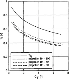
Fig. 3 Ideal efficiency and propeller open water efficiencies as a function of thrust loading coefficient CT.
It is largely the above principle, expressed in the ηI-CT relation, that holds promise for a non precedented high efficiency of the Whale Tail Wheel, at yet acceptable cavitation erosion and vibration problems.
Working principle cycloidal propellers
‘The cycloidal propulsor is a thrusting device with an axis of rotation that is approximately perpendicular to the direction of travel. A number of lifting blades (typically 4 to 7) equally spaced at a fixed orbit diameter D, rotate about this axis. Each blade is further controlled in its orbit such that a component of force in a desired direction is obtained. It is thus a special case of a controllable pitch propeller. ' (Brockett (1)).
A sketch of the cross section of a cycloidal propulsor, including reference frames and nomenclature for orientation of the blades along an orbit path, is shown in Fig.4.
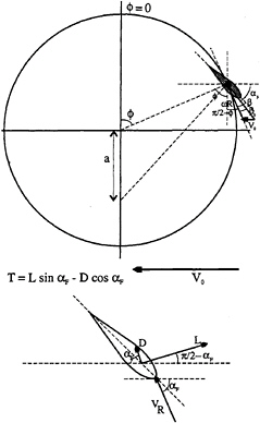
Fig. 4 Sketch of a cross section of a cycloidal propeller, including reference frames and nomenclature.
Drift or drag forces occur whenever a body is moving through a fluid and act by definition in the direction of the inflow. Examples of its application are for example the paddle of a canoe or the paddle wheel of the Mississippi Steamers.
The Whale Tail Wheel seeks to combine the benefits of both the paddle wheel and the propeller. The paddle wheel often shows a favourable efficiency because it allows for a large propulsor area and therefore a low propulsor loading. A major drawback of this propulsor is however that only a small part of the blade orbit can be used for thrust production, because of the force generation principle of drift.
This setback is avoided when thrust is generated through the principle of lift generation for blades that can be optimally oriented along their entire orbit of 360 deg. The principle of lift generation for thrust furthermore also keeps the advantage that lift is a more effective agency for force production than drift, giving promise to higher thrust production at lower rotation rates with smaller propulsors.
4.
RELEVANT PARAMETERS
Important parameters that govern the efficiency of a conventional propeller are its diameter D, its pitch-diameter ratio P/D and its blade-area ratio AE/A0. The effect of these three parameters will be discussed in the order of diminishing importance on efficiency.
The effect of the propeller diameter is reflected in the thrust loading coefficient CT, which effect is already discussed in the preceding section.
The pitch diameter ratio is an equivalent for the average blade angle of attack with the incident flow. It determines the propeller rotation rate for a given thrust requirement. For each thrust loading coefficient, a pitch-diameter ratio can be distinguished that provides an optimal efficiency. It can be found from e.g. the Bp-δ diagram, that this optimal pitch-diameter ratio increases with decreasing thrust loading. Or in other words, the optimal non-dimensional propeller rotation rate (reciprocal value of the propeller advance coefficient; 1/J) decreases with decreasing thrust loading.
A certain minimal blade-area ratio is required to give the required strength to the propeller blade for the lower thrust loadings, or to yield acceptable cavitation characteristics for the higher thrust loadings. Increasing the blade-area ratio always has an adverse effect on propeller efficiency (when compared on a base of equal thickness/chord ratio of the blade profile).
In analogy with the above prime parameters governing the propeller performance, corresponding parameters can be defined for the Whale Tail Wheel.
Wheel dimensions
Equivalent to the propeller disk area or propeller diameter is the Whale Tail Wheel envelope area A0, that is projected in the plane oriented at right angles with the propulsor heading. Because of the geometry of the cycloidal propeller, this area is not only determined by the orbit diameter of the blades, but also by the span of the blades. The larger this projected area, the lower the thrust loading coefficient and consequently the higher the ideal efficiency ηI.
Pitch or eccentricity
Equivalent to the propeller pitch-diameter ratio is the blade angle of attack along its orbit. This angle of attack is determined by the geometric blade pitch angle β and the hydrodynamic pitch angle β0, without effect of induced velocities (see Fig.4).
Perhaps the most common representation of the blade angle β(![]() ), is that of pure cycloidal motion. In such a motion, the normal to the blade nose-tail at the pivot point passes through a fixed point in space, called the pitch point. The distance between this pitch point and the orbit centre is called the eccentricity a (Fig.4). The geometrical blade angle for this motion is obtained from:
), is that of pure cycloidal motion. In such a motion, the normal to the blade nose-tail at the pivot point passes through a fixed point in space, called the pitch point. The distance between this pitch point and the orbit centre is called the eccentricity a (Fig.4). The geometrical blade angle for this motion is obtained from:
(2)
where e=eccentricity, expressed as a fraction of the orbit radius; e=a/R.
Analogous to a conventional propeller, the pitch can be introduced as the traversed path in the translation direction for one complete revolution at slip zero (β–β0=0). For a pure cycloidal motion, the non-dimensional pitch is obtained from the following relation:
(3)
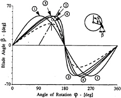
Fig.5 shows the blade angle β for a number of blade motion distributions for the same maximum blade angle value. The alternative distributions aim at either a higher propeller efficiency or at a simplified mechanical construction.
The working point of the propeller is characterized by the velocity ratio λ, which is defined as:
(4)
where V0=propeller speed of advance
n=propeller rotation rate
D=propeller diameter.
Two distinct type of blade trajectories can be distinguished, as depicted in Fig.6. For values of λ<1, we speak of an epicycloidal blade path trajectory. For values of λ>1, we speak of a trochoidal blade path trajectory. It is interesting to observe that the blade trajectory of a conventional paddle wheel is necessarily of the epicycloidal type, should a positive thrust be generated. A similar restriction in blade trajectory type holds for the cycloidal propeller with pitch ratios e<1. For pitch ratios e>1, both types of blade trajectories can be used for a positive thrust production.
-
Sinusoidal blade motion:
β(
 )=53.13°sin
 -
Cycloidal blade motion:
-
Amplified cycloidal blade motion
-
Compensated amplified cycloidal blade motion
Fig.5 Various blade angle distributions (from Brockett (1)).
The most common pitch control for existing cycloidal propellers, is that with a pitch ratio e<1, which will be referred to as low pitch. An upper limit of these low pitch values occurs near e=0.8, to restrict the accelerations experienced by the blade near ![]() =π (Mueller (17)). To obtain pitch values greater than e=1, special mechanical constructions are needed.
=π (Mueller (17)). To obtain pitch values greater than e=1, special mechanical constructions are needed.
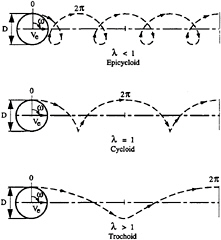
Fig. 6 Various types of trajectories described by the blades of cycloidal propellers (Van Manen (5)).
It is interesting to note at this point, that for lightly loaded cycloidal propellers (low CT value) with limited blade span, the optimum pitch ratio values e appear to be in excess of 1 (Fig.7, Van Manen (5)).
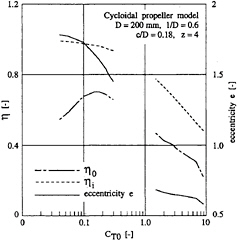
Fig. 7 Optimum efficiency and eccentricity obtained from experiments on a cycloidal propeller (derived from Van Manen (5)).
Blade area ratio
Equivalent to the propeller blade area ratio AE/A0 is for example the ratio of total lateral blade area AL to propeller envelope area A0:
(5)
where z=number of blades
l=length or span of blade
 =mean chord length of blade
D=propeller diameter.
Similar to conventional propellers, this blade area ratio is preferably kept as small as possible to minimize fractional losses. It is anticipated that strength requirements govern this minimal blade area ratio. Cavitation is expected to be a less dominating factor for the Whale Tail Wheel than it is for a conventional propeller. This expectation is based on the lower thrust loading, causing lower inflow velocities to the blades and the anticipated smaller variations in blade angle of attack for the Whale Tail Wheel. Only in the lower part of the blade orbit, a high rate of change in angle of attack is experienced.
Blade angle rate
An important parameter with respect to cavitation is the blade angle velocity distribution along the blade orbit. This parameter plays an important role with respect to the distribution of the free vortices, induced by the time derivative of the bound vortex (circulation) of the rotating blades. It is expected that the highest blade pitch rate (occurring in the lower part of the blade orbit) determines the point of inception and the character of developed cavitation, induced by these free vortices.
5.
ASSESSMENT OF PERFORMANCE POTENTIAL
Computational model CYCLOPS
Based on a computational model for performance analysis of cycloidal propellers by Brockett (1), a simplified model was implemented in the QUAESTOR knowledge base, designated CYCLOPS. A description of the knowledge system QUAESTOR is given by Van Hees (18).
As can be inferred from Fig.4, the thrust and torque are simply obtained from the profile lift and drag. The profile's lift is computed from the
following relation:
(6)
where
(7)
and V0=inflow velocity in propeller
ω=propeller rotation rate
R=radius of blade orbit
ΔUa=local increase in axial velocity due to thrust production.
The local increase in axial velocity is obtained from momentum considerations on an actuator disk, and reads:
(8)
The lift coefficient is computed from:
(9)
where t/c=blade thickness ratio.
The drag is computed from
(10)
where
(11)
The simplifications relative to the computational model by Brockett comprise the neglect of 3D effects in the flow about a foil. The Aspect Ratio of the foils of the Whale Tail Wheel are considered to have an infinitely large value. This simplification is justified by the fact that the Whale Tail Wheel can be extended over a major part of the width of the ship, allowing for large aspect ratios of the blades. The propeller blades are furthermore clenched in between two end-plates, causing a theoretical increase in effective aspect ratio towards infinity.
Another simplification is the addition of a constant and uniform induced velocity in x-direction over the total propulsor area, whereas Brockett uses an axially induced velocity that varies over the blade 's orbit.
Throughout the computation, all time derivatives have been neglected, as is the case in the model of Brockett. It is to be noted however, that especially near positions in the blade orbit, where the blade angle of attack rapidly changes, these time derivatives may have a non-negligible effect on especially torque. This would decrease the efficiency.
It is yet believed that this simple model provides a realistic indication of the upper limit of attainable efficiencies at the required thrust coefficient. Brockett concludes on his computational model the following: ‘The simple procedure for flow modelling described herein has been able to correctly predict the trends and levels of performance in powering and cavitation for cycloidal propulsors. In general, there is greater accuracy in the load predictions for high-pitch (eccentricity e>1) than for low-pitch operation, since the interaction between the blades is reduced at high-pitch operation (as it is for the conventional propeller) and the predictions appear to be more accurate for symmetrical blade sections than for cambered profiles.' (Brockett (1)).
The Whale Tail Wheel that has been evaluated for this study has blade profiles without camber (symmetrical profiles) and has the pivot point located at half chord length. To provide sufficient stiffness to the blades, a tentative number of 3 additional support disks were considered as part of the propulsor. The additional torque for these support disks has been included in the results.
Selected blade angle path
Two blade angle paths were considered during this study. First a blade angle path was computed with Sparenberg's criterion for optimal efficiency. This criterion comes down to the constraint for constant circulation about the blade section. If this criterion is met, no free vortices are shed and consequently no additional kinetic energy is lost. This criterion cannot be used however in the top and bottom position of the blade orbit (![]() =0 and π respectively). This will be explained with the Figs. 8 and 9.
=0 and π respectively). This will be explained with the Figs. 8 and 9.
Fig.8 shows the geometrical blade angle β over the blade orbit for three types of blade motion. The path indicated ‘Sparenberg' shows a non-zero pitch angle at the top position (![]() =0), due to the
=0), due to the
constant circulation constraint. This causes a significant negative thrust contribution around the top position however, as is illustrated in Fig.9. In this figure, the instantaneous thrust and torque values along the blade orbit are plotted for a Sparenberg type blade motion.
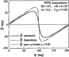
Fig. 8 Various blade angle paths for test case.
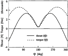
Fig. 9 Instantaneous thrust and torque for one blade during a complete revolution at constant blade circulation.
In the bottom position, the blade angle has to quickly change sign, in order to allow the blade to maintain a positive thrust contribution in the upward part of its orbit. This implies a discontinuity in the blade's circulation.
Due to the large negative contribution to thrust in the top of the blade orbit, it was argued that the efficiency of this type of blade motion could be improved. Subsequently, the blade angle was optimized for each computed step of its orbit.
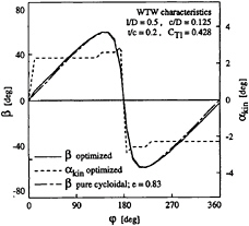
Fig. 10 Optimized blade angle path and angle of attack for test case.
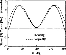
Fig. 11 Instantaneous thrust and torque for one blade during a complete revolution at optimized blade angle path.
The resulting blade angle path and angle of attack are plotted in Fig.10. Also plotted in this figure is the blade angle path of a pure cycloidal blade motion of similar pitch value (e=0.83). A good correspondence occurs between these two types of blade motion.
An almost constant optimum blade angle of attack of approx. 2.4 deg resulted from the blade angle optimization. This optimum angle will increase however for increasing aspect ratio of the blades. For the presented test case, an aspect ratio of 4 was applied. It is expected however that the trend in the angle of attack with blade position remains unaltered, and therefore the blade angle of attack was set at a constant 4 deg over the major part of the blade orbit. Adaptations to this constant angle of attack were only necessary in both the top and bottom position of the orbit.
The effect of the optimized blade angle or kinematic angle of attack (αkin) on instantaneous thrust and torque is plotted in Fig.11. Comparison of this figure with Fig.9 shows a clear difference in instantaneous efficiency (thrust/torque ratio) in the upper part of the orbit.
It is to be noted that, due to the addition of 3-D effects in the results of the latter figure, the trends in thrust and torque are comparable, but not so their absolute values however.
Analysis of Whale Tail Wheel applications
To obtain a realistic indication of the performance of a Whale Tail Wheel behind a vessel, it is not sufficient to only consider the maximum propeller efficiency attainable. One should also take the thrust requirement and allowable size of the propeller into account.
To this end, four vessel types were selected; a coaster, a short sea ferry, a high speed catamaran and an inland waterway vessel. For each vessel, the main dimensions of a representative design for that type of vessel are listed in Table 1. The total resistance for a representative design speed was then computed.
Table 1 Characteristics of selected cases
|
Designation |
Coaster |
Short Sea Ferry |
Catamaran |
Inland Waterway Vessel |
|||
|
Geometric characteristics |
|||||||
|
Lpp |
- |
length between perpendiculars |
[m] |
85.3 |
118.5 |
35.5 |
80.0 |
|
B |
- |
moulded breadth |
[m] |
13.5 |
21 |
11.5 |
11.4 |
|
T |
- |
design draft |
[m] |
5.15 |
5.8 |
1.25 |
3.0 |
|
DISV |
- |
displacement volume |
[m] |
4970 |
9000 |
77.1 |
2470 |
|
CB |
- |
block coefficient |
[-] |
0.838 |
0.624 |
0.755 |
0.90 |
|
Powering characteristics |
|||||||
|
Whale Tail Wheel |
|||||||
|
VD |
- |
design speed |
[kn] |
12.0 |
20.0 |
30.0 |
8.1 |
|
RT |
- |
total resistance |
[kN] |
175 |
635 |
129 |
100 |
|
D |
- |
propeller diameter |
[m] |
2.0 |
2.0 |
0.8 |
1.5 |
|
1/B |
- |
non-dimensional span of propeller blades |
[-] |
0.8 |
0.8 |
0.6 |
0.8 |
|
c/D |
- |
non-dimensional chord length of propeller blades |
[-] |
0.18 |
0.18 |
0.18 |
0.18 |
|
z |
- |
number of blades |
[-] |
6 |
6 |
6 |
6 |
|
CT |
- |
propulsor loading coefficient |
[-] |
0.19 |
0.16 |
0.09 |
0.39 |
|
η0 |
- |
open water efficiency |
[-] |
0.81 |
0.83 |
0.84 |
0.74 |
|
PD |
- |
delivered power |
[kW] |
1476 |
8560 |
2467 |
681 |
|
n |
- |
propeller rotation rate |
[RPM] |
46 |
67 |
161 |
63 |
|
λ |
- |
propeller velocity ratio |
[-] |
1.14 |
1.29 |
2.01 |
0.74 |
|
Conventional propeller |
|||||||
|
N |
- |
number of propellers |
1 |
2 |
2 |
1 |
|
|
D |
- |
propeller diameter |
[m] |
2.60 |
4.00 |
0.90 |
2.25 |
|
η0 |
- |
open water efficiency |
[-] |
0.51 |
0.63 |
0.68 |
0.47 |
The dimensions of the Whale Tail Wheel were roughly selected as to house a large but yet feasible propeller. To this end, the width of the Wheel was set at 80% for the monohulls and 60% for the catamaran. The wheel diameter was then selected so as to not exceed either 65% of the hull's draft or an absolute value of 2.0 m.
Whale Tail Wheel dimensions and computed performance results are listed in Table 1. The results have been computed on the assumption of a 10% increase in thrust due to the propulsor action and a 12% wake fraction.
Representative open water efficiencies for conventional propeller propulsion are listed for reference purposes. These efficiencies lie in the range from 0.45 to 0.70, the higher values for the lighter propeller loading coefficients.
Fig.12 shows the open water efficiency of the Whale Tail Wheel in relation to the open water efficiencies of a number of B-series propellers and the waterjet system, as a function of thrust loading coefficient CT. It is clearly seen that the Whale Tail Wheel is a lightly loaded propeller in the selected applications, allowing for a high propulsive efficiency.
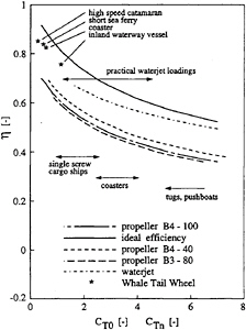
Fig. 12 Comparison of open water efficiencies of the Whale Tail Wheel, propeller and waterjet.
The open water efficiency is roughly some 10% points higher than for the propeller at the same loading coefficient. This advantage should at least partly be attributed to the lack of 3D flow effects on the foils of the Whale Tail Wheel.
It should however be noted that a comparison at equal thrust loading coefficient is interesting from the point of view of hydrodynamics, but that it is not a relevant comparison for realistic designs. This is caused by the difference in allowable propulsor dimensions. The Whale Tail Wheel allows for a much bigger envelope area A0 than the conventional propeller. And thus, the thrust coefficient of a Whale Tail Wheel is relatively lower, leading to a more favourable efficiency.
To obtain an indication of the validity of the simplified computational model, computed open water efficiencies are compared with ideal efficiencies and measured efficiencies on a low aspect ratio cycloidal propeller (blade aspect ratios of 3.3 and 5.0). These efficiencies are plotted as a function of thrust loading coefficient in Fig.13. After incorporation of the physical mechanisms that have been neglected in the present study, the Whale Tail Wheel open water efficiencies are expected to come out in between the plotted Whale Tail Wheel values and the experimental cycloidal propeller values.
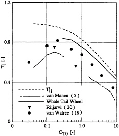
Fig. 13 Comparison of computed Whale Tail Wheel efficiencies with ideal and measured (5) open water efficiencies.
Recent data by Van Walree (19), obtained from an improved prediction model are also added. These computations were made for a cycloidal propeller with blades showing an aspect ratio of approximately 6.
6.
FINAL REMARKS
Conclusions
The present pilot study was partly based on the computer program CYCLOPS, which aims at predicting the powering characteristics of a Whale Tail Wheel. The program is based on 2D flow considerations, incorporating a rough induced flow correction based on actuator disk considerations. A few physical mechanisms have not been included yet, such as the effect of the shedding of free vortices, which is likely to occur at particularly the lower part of the blade orbit.
The present study shows that the Whale Tail Wheel has a great potential for high propulsive efficiencies for a wide variety of vessels. Preliminary estimates of the open water efficiency of the propulsor when applied to four selected vessel types show values around 80%. It is anticipated that in the computation of these efficiencies and appropriate thrust and torque values, the most important physical mechanisms are included. A number of mechanisms has deliberately not been included in this pilot study however, which are likely to cause a slightly lower efficiency in reality. The predicted values here can therefore be regarded as an upper limit of the attainable efficiency. It should be noted that transmission losses are not included in the given efficiency figures.
The relatively high efficiency is obtained for mainly two reasons:
-
The propulsor is extremely lightly loaded due to the fact that it can be extended over a major part of the width of the vessel. This increases the ideal efficiency of the propulsor and consequently the actual open water efficiency.
-
The aspect ratio of each blade approaches infinity, causing the lift/drag ratio of each blade to be much higher than in the finite lift/drag ratio propulsors such as the conventional cycloidal propeller (e.g. Voith Schneider) and the conventional screw propeller.
Due to the lightly loaded propulsor, relatively low rotation rates occur (around 60 RPM for the selected cases).
Furthermore, the blades are expected to remain cavitation free for the greater part of their orbit. Cavitation may occur in the lower part of the blade orbit, where a high blade pitch rate occurs. The very low thrust coefficient of the Whale Tail Wheel, combined with the control of blade angle rate by an adjustable eccentricity of the blades along their orbit allow for a control of cavitation inception and developed cavitation phenomena at the cost of only small efficiency reductions.
Prospects
Improvement of performance prediction
A first improvement that is readily implemented is an improved model for the induced velocities. This model should correctly account for the induced velocities of the upstream blades on the downstream blades. This is done by implementing the Vortex Latice Method (VLM). This method also allows for 3D effects about free tips of the blades ( 19) and can consequently be used for any cycloidal propulsor.
Another improvement is the incorporation of the effect of time derivatives in the hydrodynamic blade loading. This effect is incorporated through the so-called Theodorsen function, including effects of periodically shed vortices for pitch and heave motions.
As a third improvement, an empirical model for the steady lift-drag characteristics of a 2D profile for the complete range of possible angles of attack (0 to π) is implemented.
Despite the incorporation of the VLM, allowing for 3D induced velocities, the modelling of the effect of the endplates on the circulation distribution over the blades remains uncertain. As long as no reliable information for this model is available, the geometry of the blades is treated as 2-Dimensional. More certainty on the effect of the endplates will be obtained from model experiments.
Application in ship designs
The surprising aspects of the Whale Tail Wheel with the “wide and restricted draft” propulsion area are:
-
The extremely high hydrodynamic efficiency as a consequence of the realized light thrust loading.
-
The dependence of the hydrodynamic efficiency of the propeller span and as such its important effect on the choice of the ships beam, draft and length.
-
The possibility to optimize this dependence of the ship dimensions and the Whale Tail Wheel
-
for both deep and shallow water.
-
The possibility to optimize short sea vessels by integration of sea-and inland waterway transport and the elimination of cargo handling in the mainport on their way to subterminals. This elimination may lead to a substantial operational reduction of the cargo-handling costs.
-
The extremely light propeller loading of the Whale Tail Wheel (eccentricity >1) leads to a simplification of the ship's afterbody (largely 2-dimensional), to a more homogeneous wake field and consequently to favourable circumstances to avoid the risk of cavitation related phenomena like noise and vibrations.
REFERENCES
1. Brockett, T., “Hydrodynamic Analysis of Cycloidal Propulsors”, SNAME Propellers/Shafting '91 Symposium, Virginia Beach, Sept. 17–18, 1991.
2. Kirsten, F.K., “A New Type of Propeller”, S.A.E. Journal, Vol. XXII, Jan. 1928, pp. 77– 80.
3. Kirsten, F.K., “The Cycloidal Propeller in Marine Application”, University of WA, Aeronautical Laboratory, Report 322.
4. Schneider, E., “Cycloidal Propulsion Wing” (in German), Werft-Reederei-Hafen, June 1933, pp. 161–169.
5. Manen, J.D.van, “Results of Systematic Tests with Vertical Axis Propellers”, International Shipbuilding Progress, Vol. 13, Dec. 1966, pp. 382–398.
6. Henry, C.J., “A Survey of Cycloidal Propulsion”, Davidson Laboratory, Report No. 728, Dec. 1959.
7. Sparenberg, J.A., “On the Efficiency of a Vertical Axis Propeller”, Proceedings of Third Symposium on Naval Hydrodynamics (High Performance Ships) ONR ACR-65 , 1960, pp. 45–60.
8. Sparenberg, J.A. and Graaf, R.de, “On the Optimum One-Bladed Cycloidal Propeller”, Journal Eng. Math., Vol. 3, 1969, pp. 1–20.
9. James, E.C., “A Small Perturbation Theory for Cycloidal Propellers”, PhD Thesis CIT, Pasadena, 1971.
10. Nakonechny, B.V., “Experimental Performance of a Six Bladed Vertical Axis Propeller”, DTMB Report 1446, Jan. 1961.
11. Nakonechny, B.V., “Design of a 9 inch Cycloidal Propeller Model Unit and Some Experimental Results”, NSRDC Report 3150, 1975.
12. Ficken, N.L., “Conditions for the Maximum Efficiency Operation of Cycloidal Propellers ”, SNAME Chesapeake Section Paper, April 1966.
13. Bjarne, E., “Comparison of a Cycloidal Propeller with Azimuth Thrusters with Regard to Efficiency, Cavitation and Noise”, Proceedings of International Conference on Propulsion for Small Craft, RINA, Nov. 1982.
14. Kallstrom, C.G. and Loid, H.P., “Hydrodynamic Investigations of a Mine Hunter Project”, Proceedings of RINA International Symposium on Mine Warfare Vessels and Systems, Paper No. 6, June 1984.
15. Bose, N. and Lai, P.S.K., “Experimental Performance of a Trochoidal Propeller with High-Aspect Ratio Blades”, Marine Technology, Vol. 26, No. 3, July 1989.
16. Ruys, A.W., “A Comparison of Some Published Results of Tests on Vertical Axis Propellers”, International Shipbuilding Progress, Vol. 13, Dec. 1966.
17. Mueller, H., “Recent Developments in the Design and Application of the Vertical-Axis Propeller”, Trans. SNAME, Vol. 63, 1955.
18. Hees, M.Th.van, “QUAESTOR: A Knowledge Based System for Computations in Preliminary Ship Design”, PRADS'92 Symposium, Newcastle upon Tyne, May 1992.
19. Walree, F.van, “An Improved Mathematical Model for Whale Tail Wheel Analysis”, MARIN Report 13505–1-SE, April 1996.
20. Riijärvi, T., Li, J., Veitch, B.J. and Bose, N., “Experimental Performance and Comparison of Performance Prediction Methods for a Trochoidal Propeller Model”, International Ship-building Progress, 41, No. 426, 1994.
NOMENCLATURE
|
a |
- |
eccentricity; distance from pitch point to orbit centre (Fig.4) |
|
A0 |
- |
propulsor envelope area; A0=1/4πD2 for propellers, A0=Dl for the Whale Tail Wheel |
|
AE |
- |
expanded blade area of propellers |
|
AL |
- |
total lateral blade area; AL=zlc |
|
c |
- |
chord length of blade |
|
CD |
- |
drag coefficient |
|
CF |
- |
frictional drag coefficient of flat plate |
|
CL |
lift coefficient |
|
|
CT,CT0 |
- |
thrust loading coefficient; CT=T/(1/2ρV02A0) |
|
CTl |
- |
thrust loading coefficient; CTl=T/(1/2ρV02zcl) |
|
CTn |
- |
thrust loading coefficient based on waterjet nozzle area An |
|
D |
- |
diameter of blade circle |
|
D |
- |
hydrodynamic drag |
|
e |
- |
non-dimensional eccentricity; e=a/R |
|
ēφ |
- |
unit normal vector along blade orbit |
|
ī |
- |
unit normal vector in direction of heading |
|
KFy |
- |
transverse force coefficient; KFy=Fy/(ρD4n2) |
|
KQ |
- |
torque coefficient; KQ=Q/(ρD5n2) |
|
KT |
- |
thrust coefficient; KT=T/(ρD4n2) |
|
J |
- |
advance ratio; J (or Λ)=V0/(nD) |
|
L |
- |
hydrodynamic lift |
|
l |
- |
span of blade |
|
n |
- |
propulsor rotation rate |
|
R |
- |
radius of blade circle |
|
T |
- |
total thrust by propulsor |
|
t |
- |
maximum thickness of profile |
|
Va |
- |
speed of advance |
|
VR |
- |
resultant velocity kinematic |
|
V0 |
- |
free stream velocity |
|
z |
- |
number of blades |
|
αF |
- |
kinematic angle of inflow relative to (horizontal) x-axis |
|
β |
- |
geometric pitch angle |
|
β0 |
- |
hydrodynamic pitch angle without effect of induced velocities |
|
ΔUa |
- |
local increase in axial velocity due to thrust production |
|
η0 |
- |
open water efficiency |
|
λ |
- |
velocity ratio; λ=V0/(ωR) |
|
ρ |
- |
mass density of water |
|
φ |
- |
blade orbit angular position |
|
ω |
- |
angular rotation rate [rad/s] |
All quantities in SI-units


