
2
Assessment of Cutting Techniques
For any cutting technique to be effective, it must be safe, reliable, repeatable, flexible and adaptable under field conditions, environmentally sensitive, and economical. The cutting methods described in this chapter are either available to industry or are under development for use in the underwater cutting of piles, conductors, and other platform components.
Cutting techniques can be grouped into two general categories: explosive and nonexplosive. Explosive cutters presently in use are bulk charges, configured bulk charges, and other cutting charges, such as linear-shaped charges. Fracturing charges and cutting tape, such as contact and refraction tape, may have future applications. Available nonexplosive cutting techniques include mechanical cutters using hydraulically driven revolving blades; abrasive cutters using sand or slag with high-volume, low-pressure water pumps; abrasive cutters using low-volume, high-pressure water pumps with garnet injected at the nozzle; and diver cuts using oxy-arc torches. Potential nonexplosive cutting techniques may include hydraulic shears, diamond wire saws, chemical cutters, laser cutters, pyrotechnics (metal powder), chemicals, and cryogenics. None of the nonexplosive cutting techniques has been developed for commercial use, although some have been demonstrated in controlled conditions.
EXPLOSIVE CUTTING TECHNIQUES
Table 2-1 lists the three explosive cutting techniques that are presently available and some that may be available in the future.
TABLE 2-1 Explosive Cutting Techniques
|
Present |
Future |
|
Bulk explosive charges (C-4, Comp B) |
Cutting charges (explosive-shaped tape) |
|
Configured bulk charges (ring charges, focusing charges) |
Fracturing charges (contact plaster tape; shock refraction tape) |
|
Cutting charges (linear-shaped charges with fabricated containers) |
Other explosive charges (shock-wave focused, radial hollow charges) |
Present Explosive Cutting Techniques
Bulk Explosive Charges
The most commonly used technique for cutting piles and conductors is with bulk explosives. Castable and moldable explosives, such as C-4 and Comp B, have high velocity on detonation, and shattering power (brisance) that is 15 to 30 percent higher than TNT (Herbst, 1986). Comp B and C-4 are not as dangerous to handle as other high explosives and can be molded in the field to the required size and shape. After more than a quarter of a century of use and hundreds of thousands of worker-hours, no serious injuries have been reported from handling or using bulk explosives in platform removals.
During platform installation, piles are welded together in tubular sections. Cylindrical steel guides (called stabbing guides) are normally welded to the inside of the bottom of each pile section to facilitate mating with the preceding section. The inside diameter at the stabbing guide (above and below the section weld) is therefore smaller than the inside diameter of the pile. This is an important consideration for using most other cutting techniques but is only a minor inconvenience in the placement of bulk charges, which can be sized to sever the pile and do not have to be retrieved. Bulk charges can be shaped to fit pile or well dimensions that differ from the construction drawings. For example, if the smallest casing string in a well is 7 inches in diameter instead of 9.5 inches in diameter, as anticipated, bulk explosives can be reformed into a smaller container with little or no delay. Bulk explosives can also be deployed in conventional piles and wells without the use of divers.
Bulk charges are lowered into the prepared piles and wells and detonated nearly simultaneously (with a 0.9-second delay) in groups of eight or less. All of the piles and wells can be severed within an hour or two; this includes the time required to load the explosives into the structure and conduct an aerial search for turtles and marine mammals (observers for the National Marine Fisheries Service [NMFS] conduct visual searches for at least 48 hours prior to detonation). When bulk explosives are used, wells and pilings generally drop a few inches, a clear indication that they have been completely severed. High-shear-strength soils sometimes keep the piles or wells from dropping, however, which may result in the need to lift the pile with a derrick barge to verify
full cuts. Bulk explosives require minimal engineering, planning, and scheduling and (according to an explosives contractor who presented a report to the committee [Kenny, 1995]) result in a 95 percent success rate when sized properly. Increased water depth has no adverse impact on the success rate of bulk explosive cuts. If a bulk charge does not completely sever the piles or conductor, a back-up charge can be deployed quickly. The cost of bulk explosive cutting services is the lowest of all available alternatives (see table 2-2 and table 2-3). In addition to the environmental impact, the explosive force sometimes “bells” out piles and wells so piles cannot be pulled out through jacket legs. In these cases, the jacket must be lifted with the piles and the “belled” portion cut off.
Configured Bulk Charges
Improvements in the configuration of explosives such as ring charges built to collide or “focus” the explosive detonation front have been effective in localizing pile belling and reducing the weight of charges. Ungrouted piling, which may need to be removed separately from the jacket to reduce lift weight, can be removed by collision charges.
Ring Charges. Made from the same explosive material as bulk charges (Comp B or C-4), ring charges are formed into doughnut-shaped rings, which concentrates the explosive closer to the inside of the pile wall, thus making it more effective. Using this technique, the total weight of explosive charges can be reduced by approximately 10 to 15 percent.
“Focusing” Charges. These explosives are configured with steel tamping plates above and below the charge. The tamping plates have the effect of delivering more of the force horizontally, which allows reductions in explosive weight comparable to ring charges, with the added benefit of reducing or eliminating “belling.” The concept is proprietary and patented by one explosives contractor.
Both of the configured charges must be prefabricated and are sized to fit each application. There is enough size variation allowance built into each configuration to allow for small miscalculations of inside pile diameters or the dimensions of obstructions. Both types can be lowered into the pile from above, thus eliminating the need for placement by divers. Configured charges, however, cannot be used to severe wells because the diameter of the inner casing is too small to accommodate the charge.
Cutting Charges
Cutting charges include linear-shaped charges, which have been available for several years, and the more recently introduced cutting tape.
Linear-Shaped Charges. These charges use high-velocity explosive energy to accelerate a v-shaped liner material (usually copper) into a high-velocity jet (Welch, 1995) that can penetrate and cut the steel. A linear-shaped charge can be housed in a specially manufactured ring-shaped container made to fit around the outside of a pile, or it can be used with a running tool and an articulated device for making an inside cut. When accurately positioned to a precisely calculated stand-off distance between the charge and the target, smooth cuts can be obtained. The stand-off distance is a function of the thickness of the steel.
There are several limitations to using linear-shaped charges:
-
If an external charge is used to cut a pile, there is no attenuation of the explosive energy afforded by the soil.
-
To pass by stabbing guides in the pile, an internal-shaped charge must be the articulated type.
-
If the thickness of the pile section is unknown (possible in older structures), if the pile is out of round, if the charge is not placed directly against the target, or if a stabbing guide is at the proposed cut elevation, a successful cut may not be obtained.
-
Shaped charges require long lead times (several weeks) to fabricate the containers and articulated devices and cost about four or five times more than bulk charges.
-
Divers can place the shaped charges, but safety and cost considerations must be taken in consideration.
-
Performance of a shaped charge depends on the presence of an air gap between the liner of the charge and the target (pile or caisson). Water infiltration between the charge and the pile greatly diminishes performance (Welch, 1995).
Future Explosive Cutting Techniques
Cutting Charges
A refinement of rigid, linear-shaped charges that may be useful in the future is explosive cutting tape. Explosive cutting tape is a flexible version of a linear-shaped charge. The explosive and the liner are extruded into a shaped charge housed in a flexible jacket that allows the tape to contact the pile and maintain a proper stand-off distance. Although the new type charge is flexible, variations in the shape and dimensions of the liner may cause problems, and the jacket may compress in the high ambient pressures of deeper water (more than 300 feet). Divers would be required to place the charges. According to the manufacturer, who prepared a committee presentation, explosive tape is not as efficient as linear-shaped charges and may not perform well in deep water.
Fracturing Charges
Another class of explosive charges in the development stage that may have future applications is fracturing charges. Two types of fracturing charges are contact “plaster” charges and shock refraction charges. The plaster charge is placed in direct contact with the steel pile, so the explosion causes a pressure wave to propagate through the pile thickness and spalls some of the steel on the opposite side of the pile when it is reflected as a tensile wave. Pressure from expanding gas completes the cut. The charge, which is in tape form, must be deployed by a diver. This type of explosive may reduce charge weight compared with bulk explosives, but has not yet been used to remove a standing structure.
Another type of fracturing charge being developed is called a shock refraction charge, which is the size of a plaster charge and is shaped to resemble shaped charges and cutting tape. Shock refraction charges reportedly have better underwater characteristics than shaped charges and cutting tape (because compressibility is not a factor and precise stand-off distances are not required), but they still require that divers secure the adhesive charge to the pile.
Other Explosive Charges
Shock-Wave Focusing. Advances have been made in the development of shock-wave focusing charges, which are hollow charges flexible enough to be wrapped around tubular structures internally or externally. This method focuses the shock-wave energy through the target thickness and, after exerting very high compressive stress on the material elements, rapidly converts them into tensile stresses that initiate controlled brittle fractures (figure 2-1). Demonstrations in air indicate that the efficiency of this technique could result in a reduction of up to 90 percent of explosive weight compared with the charge weight required for shaped charges. Shock-wave focusing methods are particularly efficient for thicker wall targets but require that the distal surface be backed by either air or water. The shock-wave focusing tool presently used is not adequate for grout-backed targets. In the longer term, it may be possible to combine both focused and shaped charges into an integrated tool for cutting conductors.
Radial Hollow Charge. This is a short, linear-shaped charge bent into an arc with the explosives initiated simultaneously at the central axis. The charge looks like a wedge of pie. The detonation front runs radially outward, detonating the explosives simultaneously at the side of the liner and causing the liner to collapse instantaneously. This produces a flowing radial cutting jet. Because of the diverging flow, a relatively long cut can be produced on a flat or a curved target. By joining a number of these charges, it may be possible to
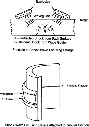
FIGURE 2-1 Shock-wave focusing. Source: Courtesy of UMIST.
cut along plates and around pipes using relatively less explosive weight (figure 2-2). The advantage of this charge is that the larger stand-off distance produces longer cuts. Radial hollow charges may also overcome some of the disadvantages of commercial-shaped charges, which require robust containers that can withstand the hydrostatic head. The stand-off (radial) distance from the surface could be adjusted to match any rounded, but irregular, surface.
None of the explosive cutting techniques, except bulk charges, can be used to sever wells with multiple casing strings except by repeated explosion done from the outside, one layer at a time. Charges that require precise stand-off distances (shaped charges, cutting tape) or adhesion to the inside of the pile (cutting fracturing tape) require clean surfaces, which means more jetting or brushing of soil from the pile than is required for bulk or configured bulk charges. All of the explosive charges, regardless of weight, would require special regulations and their use is currently restricted.
The positive and negative features of present and future explosive cutting techniques are summarized in table 2-2.
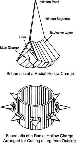
FIGURE 2-2 Radial hollow charge. Source: Courtesy of Hydrodynamic Cutting Services.
NONEXPLOSIVE CUTTING TECHNIQUES
For some applications, platform removal using nonexplosive means is the most desirable option. Thirty percent of platforms removed since 1987 have been removed with nonexplosive methods. Large-diameter caissons can be cut by divers. Shallow-water well-protector platforms allow experimental development of abrasive and mechanical cutters in the field at lower cost and less risk than in deep water.
Regulations intended to protect sea turtles and marine mammals already provide built-in incentives for using nonexplosive techniques. The time, scheduling, and expense of coordinating the Minerals Management Service and NMFS observers during explosive removals, and the restrictions on using explosives encourages operators to consider alternative methods when factors such as water depth, platform age, type, and configuration make alternative methods feasible.
Nonexplosive methods presently used include mechanical cutters, abrasive slurry cutters that use high volumes of sand or slag at relatively low pressure, and abrasive slurry cutters that use low volumes of garnet or other materials at high pressure. Another method is diver cutting using a hollow steel rod or several small exothermic rods connected to a DC power source and fed with oxygen from the surface.
Development and testing of two nonexplosive techniques—hydraulic shears for cutting braces externally and diamond wire saws —are under way. These techniques may be applicable in the future for certain types of cutting. Other ideas include laser devices, pyrotechnic metal powder cutters, chemicals, and cryogenics. Another possibility is using remotely operated vehicles instead of divers. In the following sections nonexplosive techniques that have some present applications are described, as well as techniques that may have potential for use in the future.
Present Nonexplosive Cutting Techniques
Mechanical Cutters
Cutting mechanisms that use hydraulically actuated, carbide-tipped tungsten blades to mill through tubular structures are called mechanical cutters. Mechanical cutters have been used with increasing frequency since 1987. Figure 2-3 shows a sketch of a mechanical cutter in position on a battered pile. The tool is lowered into an open pile (or well), and the power swivel is supported and connected to the top of the pile or well. The power swivel turns the drill string so that the milling blades are forced outward hydraulically to cut the pile or well. Centralizers on the tool keep it concentric inside of the pile or well. Mechanical cutters have been used most successfully for cutting shallow-water, small-diameter caissons with individual wells and shallow-water well-protector platforms with vertical piles.
On wells where the casing strings are not cemented, lateral movement after the inner string is cut causes uneven cutting of the next casing. Uncemented strings can be pulled after each successive cut, but this requires lifting equipment and time to remove and reinstall the tool each time. Concentric casing strings that are cemented together may also require trips in and out of the well to replace worn blades. Once all cemented strings are completely cut, larger lifting equipment is required for removal. Variations in casing strings may result in incomplete cuts at the outer string.
Another limitation of mechanical cutters is that pilings must be open at the surface to accommodate the power swivel. Therefore, the deck of a conventional platform must be removed using a derrick barge. Remobilizing a derrick barge with its attendant cargo barges and other support services and personnel can take several days and cost hundreds of thousands of dollars, depending on the location and size of the derrick barge. The time the derrick barge spends on location while sequential piling cuts are made is also expensive
TABLE 2-2 Assessment of Present and Future Explosive Cutting Techniques
|
PRESENT TECHNIQUES |
|
|
Positive Impacts |
Negative Impacts |
|
Environment
|
Environment
|
|
Safety
|
|
|
Reliability
|
|
|
Flexibility
|
Flexibility
|
|
Cost
|
Cost
|
|
Regulation
|
|
|
FUTURE TECHNIQUES |
|
|
Positive Impacts |
Negative Impacts |
|
Environment
|
Environment
|
|
Safety
|
|
|
Reliability
|
Reliability
|
|
Flexibility
|
|
|
Cost
|
|
|
Regulation
|
|
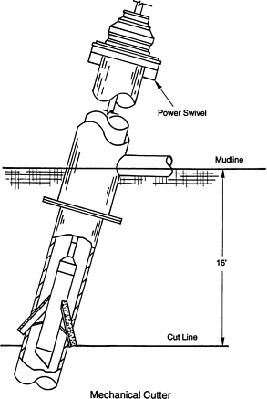
FIGURE 2-3 Sketch of a mechanical cutter on a pile. Source: Courtesy of Hydrodynamic Cutting Services.
because mechanical cuts can take several hours each and the rig-up and rig-down times may also be considerable (Herbst, 1986).
Abrasive Cutters
Mechanisms that inject cutting materials into a water jet and abrasively wear away steel are called abrasive cutters (also called sand cutters, abrasive jet cutters, or abrasive slurry cutters). There are two types presently in use: (1) cutters that use sand or slag mixed with water at relatively low pressure (4,000 to 10,000 psi) and high volume (80 to 100 gallons/minute); and (2) those that use garnet or other abrasive materials injected at the nozzle at relatively high water pressure (50,000 to 70,000 psi) with lower water volume.
The first type (commonly called a sand cutter) uses a turning mechanism, or power swivel, as a mechanical cutter. The power swivel rests on and is connected to the top of an open pile or conductor (figure 2-4). The entire drill string, or “work string,” turns the cutting head at about one revolution per minute, and the centralizing ring centers the cutting head. The cutting nozzle requires a stand-off distance of about 0.5 to 1.5 inches and delivers about 80 to 100 gallons of water per minute and sand from a 4,000-psi to 10,000-psi pump.
This type of cutter is used mostly for cutting shallow-water, open-pile, well-protector jackets; single-thickness, small vertical caissons; and wells with uncemented casing strings. Single strings of casing can be cut quickly (20 minutes cutting time each) and removed separately, but, like mechanical cutters, sand cutters require frequent trips in and out of the well. Cemented casing strings require longer cutting times, and reliability decreases with distance from the nozzle. Sand cutters have seldom been successful in cutting more than two cemented casing strings at a time. Casing string variations cause similar problems.
Sand cutters can be used on open piles after soil plugs or other obstructions have been removed. Rollers are required to move the cutter head past pile stabbing points when it is lowered and retrieved. If a mechanical failure occurs, such as a stabilizer failure or nozzle cut-out, and the tool must be
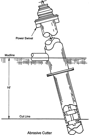
FIGURE 2-4 Sketch of a sand cutter on a pile. Source: Courtesy of Hydrodynamic
removed, a new cut may be required because returning to the same partial cut cannot be assured. The only visual evidence of a successful cut is fluid return, which is not always a clear indication of a complete cut. Determining when a cut is complete requires judgment and skill by the operator. Sand cutters require open pilings, and decks must be removed prior to deployment. The time required to cut piles varies with water depth, pile thickness, and mechanical problems.
The second type of abrasive cutter is commonly called an abrasive jet cutter. This cutter (figure 2-5) produces a cutting jet of water mixed with garnet under very high pressure (50,000 to 70,000 psi) directed through a diamond orifice. Abrasive jet cutters are relatively new and have been used for cutting wells and some pilings. There are two versions of abrasive jet cutters, external and internal. External cutters must be deployed and retrieved by divers. Internal cutters do not rely on top-drive power swivels. Instead a downhole motor turns the cutting head one revolution per cut at a speed dependent on the thickness of the cut. This allows the operator to monitor acoustically the sound level in the water outside the cut. Changes in the sound level indicate penetration of the cutting jet.
Wells with fully cemented casing strings are easier to cut with an abrasive jet cutter than wells without a cemented annulus. Fully cemented wells maintain the jet stream focus; but partially cemented wells may cause the cutting jet stream to be diffused, which slows or stops the cut. Multistring, fully cemented wells may take 1.5 to 2.5 hours of cutting time per well plus rig-up and rig-down time (Allen, 1995). Small-diameter piles (up to 42 inches) can be cut in approximately half the time it takes to cut wells.
The cost of abrasive jet cutting services is two to five times the cost of explosives; there may also be costs for additional derrick barge time if one is on location during the cuts. Additional limitations include the difficulty of returning to a cut after mechanical problems or nozzle replacement, the difficulty of maintaining a clean surface to ensure stand-off distance, and the noise level of the supersonic cutting jet.
Diver Cuts
Divers can use oxygen-fed hollow rods connected to a DC welding machine to burn through steel under water. They can also use exothermic rods, which are fed with oxygen and remain “lit” after the initial arc, to make underwater cuts. Underwater burning is generally limited to caissons, pilings, bracing, or other structural components, but not wells.
For underwater burning a general rule of thumb is that a diver can burn 1 linear inch of steel per inch of thickness per minute (Brown, 1995; Hall, 1995). A piling 1.5 inches thick would be cut at the rate of two-thirds of an inch per minute. Theoretically, a pile 48 inches in diameter with a 1.5-inch-thick wall should be cut in less than four hours. Table 2-3 compares the cost of such a cut in three different water depths. The figures are calculated for divers using surface air and
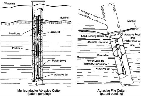
FIGURE 2-5 Sketches of an abrasive jet cutter on a well and pile. Source: Courtesy of Hydrodynamic Cutting Services.
TABLE 2-3 Cost of Diver Cuts in Increasing Water Depth
|
Depth (feet) |
Maximum Bottom Time per Dive (minutes) |
Maximum Diver Decompression Time per Dive (minutes) |
Number of Dives Required |
Total Time Required to Cut Pile (minutes) |
Total Cost of Cutting One Pile * |
|
50 |
200 |
45 |
2 |
271 |
$13,174 |
|
100 |
80 |
65 |
3 |
411 |
$19,979 |
|
150 |
50 |
90 |
5 |
652 |
$31,694 |
|
*Does not include the cost of excavating soil or maintaining the excavation. NOTE: Cost estimates provided by the Association of Diving Contractors. |
|||||
modified U.S. Navy dive tables, cutting from a derrick barge with a spread rate of $70,000 per day, including diver costs. An 8-pile jacket in 150 feet of water would thus cost approximately $250,000 using divers to cut the piling. The costs do not include the considerable expense of excavating soil outside the pile or maintaining the excavation. The same cut in 50 feet of water would cost approximately $105,000. Using explosives, the same cut would cost approximately $30,000 in any water depth.
Another consideration when using diver cuts is ability and skills vary considerably among divers, and time can be lost retracing partially cut pilings. A 2-inch-long uncut section (or hanger) of a 1.5-inch-thick pile takes 54 tons of force to yield. Under present regulations, cuts are required to be 15 feet below the mudline, so cuts made from the outside of a piling require excavation, which adds to the cost (figure 2-6). Safety is another consideration: it is dangerous to cut from the inside because of “blowback,” the explosion of oxygen and hydrogen that can build up around the periphery of the pile unless the area around the piling is adequately vented by jetting the soil away (figure 2-7). And it is always dangerous to put a diver in a pilewhere he may be suspended. It should be noted, however, that this is probably less dangerous for a diver than if he must work at the base of a deep excavation around a pile. Because of the risks, underwater diver cuts 15 feet below the mudline are controversial in the diving community. It is considered less dangerous for divers to cut from inside pilings in caissons that are 48 inches in diameter or larger where the diver is less constricted. However, excavation still poses cost and safety problems.
Future Nonexplosive Cutting Techniques
The successful field application of future nonexplosive techniques and the improvement of existing techniques will depend on the results of testing and development under way in the United States and Europe. Alternative cutting techniques have been developed in the field on actual contracts, sometimes at significant cost to the contractor or the operator. Based on the committee's investigations, most of the research in this area is being done in Europe, often funded by government and industry consortia. Research in the United States has been limited to a few studies. Techniques in the early stages of research and development are described below.
Hydraulic Shears
Hydraulic shears have jaws that close around a tubular element, like scissors. The upper jaw is driven by a hydraulic jack mounted on the lower jaw (figure 2-8). Thus the shears do not require a fixed position to operate but can be suspended from a crane with the proper rigging; the attitude is controlled by a counterweight. The position can be fixed with a hydraulic gripper. The goal of developers is to produce shears that can cut tubular elements up to 42 inches in diameter and 1.5 inches thick.
Diamond Wire Cutter
Diamond wire cutters use a steel wire with small beads embedded with diamond particles mounted on the wire at regular intervals. The wire can be made any length by joining the ends. Like the cutting mechanism of a chain saw, the wire runs over pulleys mounted on a frame. One of the pulleys is driven by an electro-hydraulic motor; another acts as a tensioner (figure 2-9).
Sometimes confirming cuts by diamond wire cutters is difficult. When the reliability of these cutters improves, confidence, and acceptance of the technique will increase. At present, diamond wire cutters are limited to cutting medium-to small-size tubular structures and standard steel shapes. The size of the equipment will probably limit the development and potential use of this technique. The prototype proved capable of cutting various shapes in test conditions simulating an offshore platform (the deck of a large semisubmersible derrick barge), although cutting structures under compression caused the mechanism to jam if the cutting was interrupted.
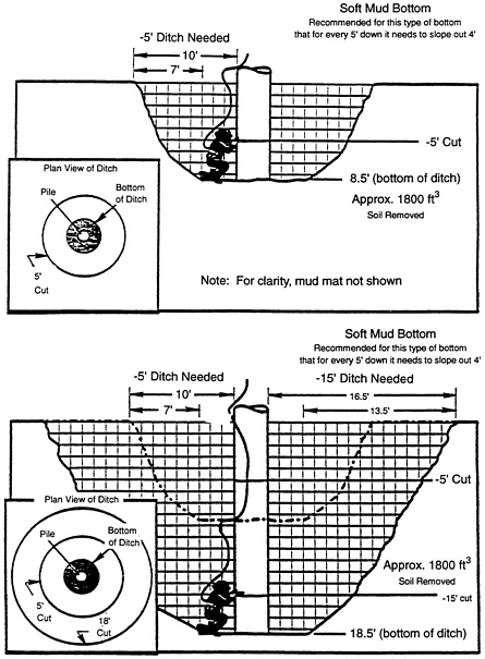
FIGURE 2-6 Excavation required for external diver cuts. Source: Courtesy of Association of Diving Contractors.
The cost, reliability, safety, and routine application of diamond wire cutters for removals in the Gulf of Mexico cannot yet be determined because, given the risks and high cost of failure, companies have been unwilling to test them in actual field operations.
TECHNIQUES BEING DEVELOPED
Laser Cutting
The laser cutting technique uses beams of coherent light focused onto the material to be cut, which creates high enough temperatures in a concentrated area to vaporize the material. Laser cutting requires considerable further development of both process and equipment to determine the feasibility and cost effectiveness of offshore use.
Pyrotechnic Cutting
Pyrotechnic cutting relies on an exothermic reaction that produces a high-velocity jet of molten iron that penetrates the target material. The equipment consists of a reusable torch and iron oxide reactants; an excess of aluminum that reacts with nickel to raise temperatures; and polytetrafluoroethylene, which helps expel the jet through the graphite focusing nozzle at high speed. The cutting action results from
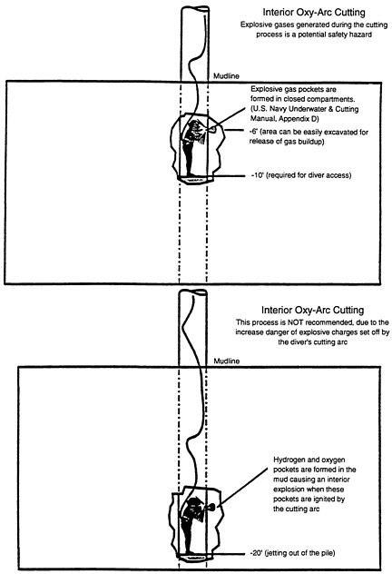
FIGURE 2-7 Sketches showing internal diver cut. Source: Courtesy of Association of Diving Contractors.
melting the target material, which produces a crater or hole. The charge is placed and detonated in the same way as an explosive charge and is self-sustaining once it is initiated (figure 2-10). This technique requires highly efficient thermite mixtures and automated systems to produce linear cuts.
Cryogenics
For the cryogenics technique the steel is cooled to a brittle stage with liquid nitrogen and then cut with a small charge or mechanical hammer. The amount of nitrogen necessary for reflective cooling has not been determined with any degee of certainty. There is also still some uncertainty about how long it takes to cool the steel and about the size of the ice plug. All of these appear to be issues that can be resolved. Further work is required on the practical aspects of applying the nitrogen and understanding how it affects the sarrounding soil.
Chemical Cutters
The chemical cutter technique uses highly corrosive liquids such as hydrofluoric compounds that are squirted from chemical flasks pressurized by a pyrotechnic mixture. Multiple jets are used to produce a series of closely packed perforations inside the casing. This technique is rarely used because of the hazardous nature of the compounds. New
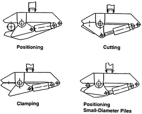
FIGURE 2-8 Hydraulic shears. Source: Courtesy of THC Handling Systems.
techniques have been developed using inert chemicals in separate containers, which are punctured in situ to allow the chemicals to combine. The reaction produces a corrosive liquid for perforating the structure.
Other projects are underway to adapt the electro-chemical machining process, which has been used successfully in the manufacturing industry, for subsea applications. This method requires an electrical current to be passed through the cutting jet to accelerate the erosion process. The pressure of salt water improves the efficiency of cutting.
Deployment of Remotely Operated Vehicles
Remotely operated vehicles (ROVs) are commonly used in underwater operations such as photography, visual observation, the manipulation of valves, and the delivery or recovery of lightweight materials in deeper water. ROVs are also used in deep-water dredging operations and for cutting steel beams (up to 2 inches by 12 inches). ROVs have been considered for use in platform removal for both economic and safety reasons. Tools mounted on ROVs can be configured to handle and deploy both explosives and some types of mechanical cutters. Although the technology to do this exists, the procedure is complicated and expensive, albeit less costly than using divers at depths requiring mixed gas and decompression. ROV tools must be configured for each application. For platform removals, many different ROV configurations would be required to carry out a variety of tasks and to accommodate various platform shapes and sizes. Because of their size, outside power source, tether requirements, and maneuverability, ROVs may be too unwieldy to work in confined spaces—for example under mud mats or inside conductor arrays. A great deal of planning and preliminary work would be required to use ROVs in removal operations. But there is little doubt that when ROVs can be configured to perform tasks that divers are unable to do because of water depth they will be widely used in platform removals.
Bubble Curtains
Bubble curtains have been used with some success in shallow, protected waters to attenuate the blast pressure of detonations (Regalbuto et al., 1977). Bubble curtains are created by pumping compressed air through perforated piles installed on the seafloor around the detonation site. The rising air expands to the water surface creating a “curtain” of water under low pressure. It is not known if a bubble curtain would work offshore to reduce fish kill around a platform. Certainly there are significant problems with using bubble curtains:
-
A substantial pipe network would be required.
-
A large surface vessel, probably a derrick barge, would be necessary to support the operation (to house compressors, for example).
-
The effectiveness of the curtain in open water more than 100 feet deep in the presence of currents is not known.
-
Fish inside the curtain would have to be removed somehow (or they will be killed).
Acoustic Devices
Acoustic devices have been successful in keeping fish 100 feet or more away from platforms in very shallow water; for example, acoustic devices have been used effectively to keep
FIGURE 2-9 Diamond wire cutter. Source: Courtesy of HeereMac.
fish away from water intakes for power plants. Their effectiveness offshore has not been demonstrated, although it appears to be promising from the limited data available. Much more work needs to be done on acoustic devices, such as establishing power requirements, determining frequencies for different species of fish, and so on.
Platform Design Considerations
Over the past few years, suggestions have been made for incorporating into the original platform design ways of making platform removal easier and possibly less damaging to marine life. This topic was considered by the committee but was not a focus of recommendations for the following reasons:
-
There is no way of knowing what types of marine removal equipment will be available in the future. It is likely that in the long interval between the time a platform is designed and when it is removed (20 to 30 years) new, efficient tools will be developed—tools the original designer did not foresee and which make current removal methods obsolete.
-
Even if a removal strategy is designed into an installation (using assumed criteria), there is no way of knowing what the condition of the structure will be 25 to 30 years later, given the rigors of the marine environment.
-
Legal considerations and regulations are constantly changing. A designer must necessarily base the design on current regulations and cannot predict which regulations are likely to be in effect in 20 to 30 years, when the structure is removed.
-
Incorporating removal techniques into the original design could have an adverse effect on the long-term integrity of the platform (i.e., the ability to withstand the rigors of weather and ocean conditions over the lifetime of the structure). Considerable engineering and technical research are needed to incorporate safe removal into the original design. This is the first step in designing platforms for more efficient and less environmentally damaging removal in the future.
The advantages and disadvantages of various nonexplosive cutting techniques are summarized in table 2-4.
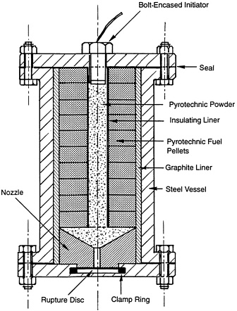
FIGURE 2-10 Pyrotechnic torch. Source: Courtesy of HeereMac.
TABLE 2-4 Assessment of Nonexplosive Cutting Techniques (present applications)
|
Positive Impacts |
Negative Impacts |
|
Environment
|
|
|
Safety
|
|
|
Reliability
|
|
|
Flexibility
|
|
|
Cost
|
|
|
Regulation
|
REFERENCES
Allen, J. 1995, Hydrodynamic Cutting Services. Presentation to the Committee on Techniques for Removing Fixed Offshore Structures, Marine Board, Houston, Texas, January 10.
Brown, M. 1995. Personal communication from Mike Brown, Diving Operations Manager, Global Divers and Contractors, February.
Hall, S. 1995. Personal communication from Steve Hall, Diving Operations Manager, Oceaneering International, Inc., Gulf Coast Division, February.
Herbst, L. 1986. Platform Removal Techniques. Technical Assessment and Operations Support Section, Field Operations . Minerals Management Service, Unpublished report, December,U.S. Department of the Interior, Washington, D.C.
Kenny, J. 1995. Kenny Enterprises, Inc. Presentation to the Committee on Techniques for Removing Fixed Offshore Structures, Marine Board, Houston, Texas, January 10.
Regalbuto, J.A., A.A. Allen, K.R. Critchlow, and C.I. Malme, eds. 1977. Underwater blast propagation and effects, George F. Ferris (drilling rig), Kachemak Bay, Alaska. Paper presented at the 9th Annual Offshore Technology Conference, OTC 3035, Houston, Texas, May 2–5.
Welch, B. 1995. The Ensign-Bickford Co. Presentation to the Committee on Techniques for Removing Fixed Offshore Structures, Marine Board, Houston, Texas, January 10.


