
Measurements of Surface Stability of Engineered Geodetic Control Points
Roger Bilham
CIRES Dept. of Geological Sciences, University of Colorado-Boulder
Athough tectonic deformation is driven by stresses deep within the Earth it can be measured only close to the Earth's surface, where signals are contaminated by displacements generated by variations in groundwater hydrology, atmospheric temperature and pressure, and solar radiation. By suitable control-point design it is possible to suppress some of these surface-signals, however, rarely are measurements undertaken to assess the stability of an improved control point. The horizontal stability of surface monuments can be measured with inclinometers and tiltmeters, and their vertical stability with simple extensometers. Although it is generally assumed that monument noise falls to insignificant levels below 10 m depth few experimental data are available to quantify this assumption. Data from several experimental monuments in clays are described that yield measured stabilities of ±0.5 mm/year despite significant variations in soil moisture content.
INTRODUCTION
The Earth's surface offers us a two dimensional view of subsurface tectonics, upon which are superimposed signals of non-tectonic origin. Non-tectonic signals are generated by temperature, pressure and moisture changes at the Earth's surface, and because they are usually not of interest and reduce the accuracy of observational geodesy, they are classed as noise. Recent improvements in GPS survey accuracy (Bevis et al., 1997) provide survey accuracies approaching 3 mm and further improvements are anticipated. Hence it is considered desirable to suppress surface noise to sub mm levels at all frequencies of interest.
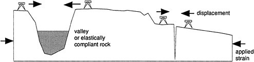
FIGURE 1 Elastic discontinuities (topography, fissures or variations in elastic modulus) on the Earth's surface result in local amplification of applied strain-fields.
A second form of noise arises from the distortion of the tectonic strain-fields by elastic heterogeneity of the Earth's surface. Mountains, open fissures, cliffs, or changes in rock strength will either interact with tectonic signals to distort their surface expression, or they will generate local signals with wavelengths similar to the scale of the feature. Examples are shown schematically in Figure 1, Figure 2 and Figure 3. Horizontal strain fields applied to a vertical fissure or a cliff, for example, are manifest as displacements of the edge of the fissure. This signal will add to, or subtract from, the observed deformation field depending on the placement of the monument. A common example of fissure enhancement is the concentration of tectonic strain across faults in the form of fault creep.
These “strain-coupled” signals are generally less than a few mm for features smaller than a few km (King and Bilham, 1973) unless the signal, or noise source, is itself very large. An example of a large noise source amplified by a surface discontinuity is the edge of south-facing cliff (Figure 2). In this case, both the Earth's upper surface and the edge of the cliff are free to expand. The thermal coefficient of most rocks is of the order of 1 ppm per degree Celsius, and if the rock is absorptive the surface may cycle by several tens of degrees daily and annually. The thermoelastic expansion of the surface layers of a 100 m high cliff may result in a daily displacement exceeding 1 mm for every 10°C. The conductivity of rock is sufficiently low for the layer undergoing these daily cycles to be small (e.g. Å20 cm), although seasonal cycles will penetrate much deeper, resulting in annual signals of several mm. If the surface rock is competent (free from cracks and weathered layers), strain changes can penetrate large distances, forcing the cliff to respond significantly to daily cycles. This, of course, is the primary forcing-function of rock exfoliation.
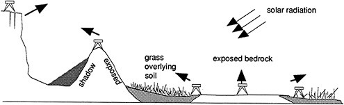
FIGURE 2 Schematic displacements caused by thermoelastic expansion of rock surfaces. Shadows, vegetation and insulating sediments perturb the insolation field causing lateral and vertical thermoelastic displacements of exposed surfaces.
Although the example given is extreme, many geodetic monuments are located on mountain sides and cliff edges where small diurnal and seasonal fluctuations in position are commonly encountered which may contaminate geodetic measurements seeking sub-cm precision. Less obvious sources of diurnal thermal instability can be found in urban settings where asphalt can attain very high temperatures. For example, a monument placed in a field at the edge of a large parking lot on a hot day will be displaced laterally by thermal expansion of underlying materials (c.f. Figure 2). This is caused by the differential absorption of the road-surface and by the insulating effect of the vegetation. Although the subsurface rock may be identical beneath both, the parking lot causes the materials beneath it to respond more rapidly to incoming radiation, and hence act as a local noise source.
Substantial lateral and vertical displacements can be generated by subsurface changes in water table (Figure 3). Consider a vertical crack 10 m by 10 m in area which is normally dry but filled with water during occasional rainfall events. The lateral force introduced by filling this crack with water exceeds 400 metric tons. Typically these hydraulic forces are balanced throughout the rock mass, but where asymmetry exists due to hydraulic gradients (time or space) large lateral surface motions can occur. In Iceland lateral motions exceeding 15 mm were observed in basalt blocks bounded by surface fissures during the filling of a dam. In the case of horizontal cracks a change in hydrostatic pressure will lift the free surface. This has been observed at Piñon Flat Observatory operations (Wyatt et al. 1984).
Phase changes and chemical alteration also generate local displacements. Ice wedging is a well known source of noise in temperate and arctic regions, and the growth of halite in marine cliffs can result in the movement of loose blocks. Tree roots can also shift surface blocks, but by far the most common source of surface noise is the hydration of clay minerals caused by changes in soil moisture. Clay minerals cause near-surface fault zones to act as hydraulic jacks in response to variations in moisture content.

FIGURE 3. Hydraulic forcing of horizontal and vertical fissures caused by variations in groundwater or soil moisture content in clays.
Soils are attractive locations to install monuments because they act as an insulating layer of loose materials preventing the transmission of thermoelastic strains into underlying layers. However, soils are known to be mobile, and geodesists have learned not to install a monument in soil unless alternative bedrock exposures are unavailable. Unfortunately, large parts of the Earth's surface are sedimentary basins covered with clays, and engineered monuments are necessary to suppress surface noise in these settings.
It is usually assumed that surface-induced noise attenuates with depth because atmospheric, thermal and hydraulic variations are a maximum at the Earth's surface. However, the rate at which surface noise decays with depth has rarely been measured, hence the guiding principle in monument design hitherto has been to go as deep as economically possible, or to “refusal”. If either of these techniques suppresses noise to acceptable levels then the monument is judged a success. What is an acceptable noise level? Typically any suppression in noise is typically regarded as acceptable, although the residual noise may still exceed the signal at some periods of interest. For example, the suppression of diurnal noise may be significant, but variations in soil moisture content over several years may displace the monument irreversibly.
Such an approach is thus inherently unsatisfactory because it does not satisfy a fundamental condition of scientific methodology, namely, that experimental results be testable. Frequently no measure of local noise level exists before or after the installation of an engineered monument, and typically, the only test that can be applied to a control point is its identification as an outlier if its measured signal fails to fit a deformation field constrained by nearby monument motions.
Those experiments that have been undertaken, illustrate that the decay of surface noise with depth is site dependent. Experiments at Piñon Flat Observatory which is located on a weathered granite show that substantial suppression of horizontal and vertical surface noise occurs at depths of Å10 m (Wyatt, 1982;1989). In this case the suppression of surface noise is evident in the reduced noise level of laser strainmeter data after the removal of displacements between the strainmeter end points and subsurface attachment points. A clear reduction in noise level is observed in engineered control points in surface clays (Langbein et al, 1995). Although such experiments imply that the wavelength of a significant fraction of surface noise in this environment is less than 10 m, they do not address the more interesting question of how much more noise would be suppressed by going to deeper depths, or whether shallower attachment points might be equally effective.
In principle this problem can be solved experimentally by measuring the spectral density of signals at successfully deeper depths and by determining their rate of decay. Then supposing that noise levels decay monotonically with depth one might then be able to design a monument for that site, with an acceptable noise level obtained by indexing the surface monument to the appropriate depth. Such experiments are tedious if they must be undertaken at every control point in a network.
Estimates of the attenuation of horizontal noise level can be obtained at a given site using an inclinometer (Bilham, 1993). An inclinometer is a commercially available tiltmeter designed to measure tilt at contiguous locations down a grooved lining cemented into a boreho1e. Typical applications are in the monitoring of dams and embankments, landslides and creeping hillsides. Each 0.5 mm increment of the
borehole can be re-occupied to mm accuracy and measured to a tilt accuracy corresponding to 0.01 horizontal-mm per vertical- m. Random errors in measuring the lateral deflection of a borehole increase as 0.6ÃL mm, where L is the depth in km (Bilham, 1993). The horizontal accuracy down-hole is thus comparable to the vertical accuracy obtained with first order spirit-leveling on the surface.
A study in Colorado (Figure 4) revealed that significant attenuation of lateral displacements below 8 m occurred in a vertically bedded shale overlain by boulder clay. A more recent study in a clay-sand environment in California, showed no such simple suppression of noise with depth (Figure 5). The data in Fig.5 are somewhat unusual in that they are obtained within 7 m of a creeping fault that slipped 24 mm during the 3 year time interval of the measurements. Noise in the east borehole (squares) falls in the first two meters but increases briefly at 23 m. Noise in the west borehole (filled circles) is low in the uppermost and lowermost 5 m but doubles between 5 and 7 m depth, decaying to low values where the vertical borehole pierces the 75° SW dipping fault.
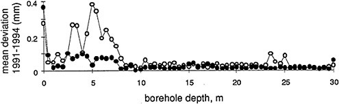
FIGURE 4 Attenuation of lateral noise in repeated measurements of a 30 m deep borehole at Table Mountain, Boulder, 1991-4. Below 8m the data appear relatively noise free.

FIGURE 5 Mean lateral deviations at subsurface increments in two 28-m-deep boreholes. The data represent ten-sample-averages of lateral offset in contiguous 0.5 m segments of each hole 1993-7. The two boreholes are vertical (±1°), 30 m apart, and 7 m from the surface expression of the Hayward fault in Fremont, California. The west borehole intersects the Hayward fault at 21±2 m depth.
The inclinometer borehole examples cited offer little guidance for general conclusions concerning the decay in noise with depth. However, the inclinometer method potentially provides a way to measure the lateral stability of geodetic control points. In principle, an inclinometer borehole can be incorporated into engineered monuments at little extra cost, and can be periodically measured to monitor long-term fluctuations relative to its base. Sub mm measurement accuracies can be obtained for boreholes less than 50 m deep.
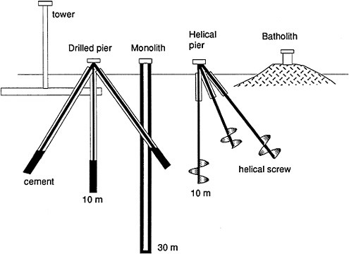
FIGURE 6 Schematic views of monuments discussed in text.
It has been known for many years that increased surface noise suppression is obtained by increasing the measurement length of a strainmeter or tiltmeter. Instruments with dimensions of the order of 1 km out-perform instruments <1m long largely because the signal is increased by a factor of 1000 relative to the random-walk noise-level of an attachment point. The same principle suggests that a 10 m wide attachment point will obtain a factor of 1000 improvement in position stability relative to a 1 cm diameter rod driven into the surface. Although this assumption is reasonable, it may be inappropriate if noise signals with wavelengths less than 10 m are absent.
Flawless crystalline rock can rarely be surpassed for control point stability (Figure 6) and a marker embedded in rock is typically subjected only to thermoelastic motions. In general, for soil installations, it is essential to increase the dimensions of a control-point to several meters at least. If a large slab of concrete is used as a monument in unconsolidated sediments its stability increases with area as long as it is rigid. However, a tower constructed on a concrete pad will amplify motions of the pad if the foundation is short compared to the height of the tower. Because thermoelastic and moisture-induced tilt variations in short platforms have been observed to exceed 100 microradians daily, diurnal movements at the top of a 10 m high tower would exceed 1 mm. To avoid amplifying surface noise, a rule-of-thumb is that the foundation must be rigid, and must be as wide as the tower is high. If a large horizontal foundation is impractical, and deep unconsolidated materials are present, the foundation should extend below ground as far as the tower extends above ground.
Three approaches to anchoring a control point at depth are shown in Figure 6 A summary of other methods can be found in Bell and Bryant (1992). In a popular method pioneered Wyatt (Langbein et al. 1995) four inclined rods are cemented into drilled holes radiating from a central rod to which they are welded approximately 2 m above ground. The monument is suitable for installation in rock or unconsolidated materials and is preceded by drilling open holes into the base of which cement is injected, and the steel rods inserted. Collars isolate near-surface layers from the completed monument.
Another promising method suitable for clay soils employs helical piers. Helical piers have been used for many decades to support bridges across rivers, and to
stabilize hill slopes. The helix consists of one or two 20-cm-diameter propellers welded to the base of a thick steel bar which is driven clockwise into the ground by a hydraulic torque converter attached to a backhoe. Additional 5-cm-square, 3-m-long steel bars are added as the pier pulls itself into the subsurface until the assembly refuses to go further, or until the required depth has been reached. The piers can be driven at any angle and can be withdrawn anticlockwise and repositioned if they encounter large boulders. The ends of three or more steel inclined piers are welded together to form a stable subsurface tripod. We have used this method to anchor creepmeters on each side of the Hayward fault in California using the geometry shown in Figure 5 but terminated 1 m below the surface. A symmetrical quadrapod or tetrapod is desirable for above ground attachment to avoid thermoelastically induced lateral displacement of the control-point.
The monolith shown in Figure 6 consists of a reinforced steel concrete monument poured in place within a 15-30 cm diameter borehole. The center of the monolith hosts a 7 cm diameter plastic inclinometer lining. Two orthogonal grooves permit biaxial tilts of the monolith to be monitored throughout the column (Bilham 1993). As discussed above, this form of monument permits the long term stability of the monument to be monitored to sub-mm precision, and also permits estimates of the effectiveness of noise suppression as a function of depth to be evaluated.
The stability of all of the monuments illustrated is no better than the stability of the deepest part of the monument, and in general the stability of the surface attachment point relative to the base of the monument is assumed to be adequate (sub mm). In principle several methods may be borrowed from strainmeter and tiltmeter technology for monitoring surface motions relative to the subsurface.
For example, the inclinometer monolith automatically provides a measure of lateral offset and can be included in both of the buried multiple anchors. An example, from the Hayward fault, is shown in Figure 7. At Point Pinole the central helical pier (7 m deep) was constructed from 8 cm diameter steel tube instead of 5 cm solid steel bar. An inclinometer tube was cemented within this hollow central pier, and two inclined solid helical piers provided short term lateral stability of the attachment point as shown in Figure 6. Despite operating in a thick clay deposit of variable moisture content, the biaxial inclinometer data reveal that the tops of the piers have moved less than 0.5 mm during their first 18 months of operation.
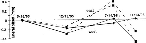
FIGURE 7 Biaxial lateral stability of two helical pile monuments at Point Pinole relative to points 7 m deep over a 18 month period. The installation material is clay.
Towers and buildings are sometimes utilized as GPS monuments because no alternative sites are available with a suitable combination of security and sky coverage, or because telemetry or recording facilities are more easily available from these locations.
The inclinometer method can be extended to control points that are currently installed on the tops of existing buildings. Concrete, or brick structures, even those that after centuries show no signs of collapse, undergo cyclic thermal and hydraulically induced deformation whose amplitudes are often difficult to assess. An inclinometer tube attached to the building can monitor seasonal and secular tilt of the building more accurately than most geodetic alternatives, and in some circumstances it may be possible to insert an inclinometer tube from the control point to levels tens of meters below the basement of the building (Figure 8). Sub mm monitoring accuracies can be anticipated from buildings in which high frequency tilt noise is absent. The method is
unsuitable for high rise buildings or compliant towers subject to vibration caused by wind stress, or the movement of elevators etc.
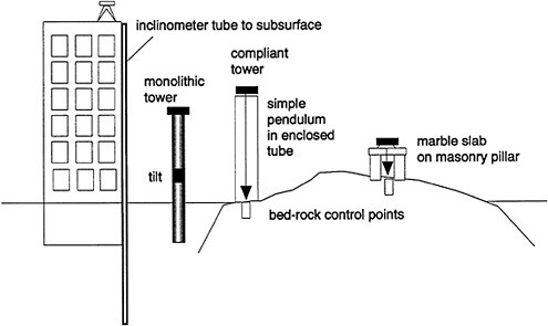
FIGURE 8 Building and tower GPS antenna installations showing schematic methods to monitor the stability of the upper point relative to subsurface, or bed-rock markers.
In installations of GPS antennae in Japan, tiltmeters are fixed to towers to monitor their secular stability (Tsuji et al. 1995). Tiltmeters are suited to tower monuments that are rigid, and that do not experience large short-period accelerations, or diurnal thermoelastic flexure. To monitor the stability of a 6 m steel tower in Cayaco, Mexico, a simple pendulum was arranged to monitor the position of the upper control point relative to a bedrock control point at its base. In this arrangement the flexibility of the tower is immaterial and the presence of short term noise is suppressed by immersing the plumb-bob in oil. The position of the plumb bob is monitored electronically.
A similar method is used to monitor the secular position of fixed GPS antennae relative to existing bed-rock control points in the Himalaya. A permanent antenna monument is constructed in the form of a three-sided brick pillar above the bedrock point. The 0.5-1.5 m high masonry is surmounted with a marble slab (polished and flat) in which a 2 cm diameter hole has been cut. The slab is set precisely horizontal and centered exactly over the fiducial mark and the GPS antenna bolted directly to the slab without additional alignment. A plumb bob is used to align the antenna precisely in position over the bedrock control point. The method provides good stability and permits long term misalignment to be detected and corrected to sub mm precision.
Thus far the discussion of monument stability has been confined to monitoring lateral motions of control points relative to points at depth, partly because GPS vertical accuracies are currently much worse than horizontal accuracies, and partly because horizontal displacements are significantly more of a challenge to suppress or monitor than vertical measurements. Theoretically, the engineered monuments shown in Figure 6 all provide sub-mm vertical stability. The vertical stability of bench marks driven to refusal is reasonably well understood (Floyd, 1998), although measurements of the resulting stability are rare. Where a vertical monument must emerge above the surface it is desirable to use invar (36% Ni alloy with a <1 ppm/°C thermal coefficient). Assuming temperature fluctuations of 50°C in a 2 m exposed tripod the maximum vertical variation is approximately 1 mm for steel and 0.1 mm for invar.
Measurements of vertical position relative to points at depth are fundamental components of long-baseline tiltmeters and strainmeters (Wyatt et al. 1984; Wyatt 1989) and measurements can be made to µm accuracy using laser strainmeters, or invar rods (Figure 9). Recently optic fibers have shown utility in measuring borehole strain (M. Zumberge, personal communication, 1996). Thick glass fiber rods are available commercially
in continuous lengths of several hundreds of meters for monitoring vertical compaction of dams and slopes. The fibers are maintained in tension and surface motions monitored using displacement transducer sensors. The sub-µm accuracy available for monitoring vertical motions is more than adequate for the Å1 cm noise level commonly available to GPS measurements.
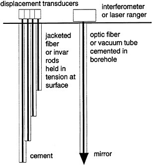
FIGURE 9 Common methods to monitor vertical motions of subsurface points. The probes are cemented into borehole that can be vertical or inclined and do not need to be perfectly straight. Measurement accuracies are typically 1 µm.
The heavy machinery needed for engineered monuments in soils and alluvium result in costly installations. Drilled monuments or helical piers to 10 m depth cost $2000-$6000 depending on drilling difficulties. The additional costs of adding vertical or horizontal monitoring facilities may add an additional 10%-20% to the total, depending on whether the monitored variables are continuously recorded or manually observed. However, given that several new GPS receivers include environmental monitoring channels, the costs of recording monument stability continuously need not be excessive. The benefit to the geodesist is that these measurements provide a measure of long term stability of the control point, enhancing the integrity of the experiment.
A future development that is clearly overdue given the limited precision of GPS geodesy, and the noisy surface environment to where these measurements are confined, is to consider future geodetic monuments that include not just measurements of surface noise, but measurements of crustal tilt and strain signals. These technologies currently yield measurement precisions that are approximately three orders of magnitude higher than the best available geodetic accuracy. For example, whereas a pair of GPS receivers 1 km apart can provide a strain precision of a few microstrain, a borehole dilatometer or a borehole tiltmeter can usually obtain a precision of a few nanostrain. Moreover, the measurement of displacement and its spatial derivatives provide powerful constraints on interpreting the nature of crustal deformation signals, constraints that are unavailable to monitoring these parameters in isolation. It is conceivable that future geodetic monuments may be equipped with tilt and strain monitoring capabilities, sampling these parameters at depths of 50-200 m, with secondary instrumentation monitoring the motion of the surface monument relative to these more stable and more precise measurements.
Despite recent improvements to geodetic monumentation in crustal deformation monitoring arrays seeking accuracies approaching or exceeding 3 mm/year, few experiments have been undertaken to assess the resulting noise level of these monuments. Geodetic tests comparing noise levels before and after monument improvement are rare, and monuments instrumented to monitor control point stability relative to points at depth are rarer. Inclinometer methods to monitor horizontal motions of monuments relative to points at Å30 m depth yield sub-mm accuracy, and vertical extensometers are easily installed to monitor vertical motions to several µm accuracy. Measurements obtained thus far confirm that atmospherically induced ground displacements are attenuated with depth, but suggest that the rate of attenuation is site dependent. In view of the widespread absence of numerical data to assess the effectiveness of horizontal and vertical noise suppression in engineered monuments, it would appear useful to include simple measurements of lateral and vertical stability in future monuments. The cost of these additional monitoring
programs might increase the initial cost of a drilled monument by 10%, but they would provide confidence in subsequent geodetic data.
Bell, L. and M. Bryant, An overview of existing permanent GPS monuments in the US and Canada, Space Geodetic Site Subcommission, IUGG Int. Coordination of Space Techniques for Geodesy and Geodynamics Newsletter, 3, 7-59, 1992
Bevis, M., Y. Both, P. Fang, R. Reilinger, T. Herring, J. Stowell and R. Smalley Jr., Blending old and new approaches to regional GPS Geodesy, Eos. Trans. Am. Geophys. Un. 61-66, 78, 6, 1997.
Bilham, R., Borehole Inclinometer Monument for Millimeter Horizontal Geodetic Control Accuracy, Geophys. Res. Lett. 20, 2159-2162, 1993.
King, G.C.P. and R.G. Bilham, Strain measurement instrumentation and technique, Phil.Trans. Roy. Soc. London, A 274, 209-217, 1973.
Langbein, J. O., F. Wyatt, H. Johnson D. Hamann and P. Zimmer. Improved stability of a deeply anchored geodetic monument fro deformation modeling, Geophys. Res. Lett. 22, 3522, 1995.
Tsuji, H., Y. Hatanaka, T. Sagiya and M. Hashimoto, Co-seismic crustal deformation from the 1994 Hokkaido-Toho-Oki earthquake monitored by a nationwide continuous GPS array in japan. Geophys. Res. Lett., 22, 1669, 1995.
Wyatt, F., Displacement of Surface Monuments: Horizontal Motion, J. Geophys. Res., 87, 979-989, 1982.
Wyatt, F., Displacement of Surface Monuments: Vertical Motion, J. Geophys. Res., 94, 1655-1669, 1989.
Wyatt, F., R. Bilham, J. Beavan, A.G. Sylvester, T. Owen, A. Harvey, C. MacDonald, D.D. Jackson and D.C: Agnew, Comparing tiltmeters for crustal deformation measurement: A preliminary report, Geophys. Res. Lett., 11, 963-966, 1984.
Charles Meertens, Christian Rocken, John Braun, Bruce Stephens, Christopher Alber, Randolph Ware
University NAVSTAR Consortium
Michael Exner
University Corporation for Atmospheric Research
Paul Kolesnikoff
Ball Aerospace
High-accuracy GPS observations can be affected by the GPS antenna type and mount. However, these effects can be corrected using anechoic chamber or field measurements. The corrections range from the 1 mm level to the 100 mm level for commonly used geodetic quality antennas and mounts, but the residual errors may be as large as 20 mm. In order to calibrate a variety of geodetic antennas and mounts, we conducted tests on short baselines in the field and in a state-of-the art anechoic antenna chamber.1 The results are summarized here and are described in detail in the UNAVCO Academic Research Infrastructure (ARI) Receiver and Antenna Test Report.2 Also examined here are the effects of high and low antenna heights, snow at the site and protective antenna radomes.
Antennas can be characterized by phase center offsets and by phase and amplitude patterns for L1, L2 and L3 (ionosphere free) tracking as a function of azimuth and angle. We define the offsets as the average phase center locations relative to a physical reference point (typically used in RINEX files) on the antennas, and the patterns as the azimuth and elevation dependence of the phase centers and amplitudes. We measured these antenna properties in the Ball Aerospace anechoic test range chamber located in Broomfield, Colorado.
We ran the chamber tests using the antenna and low-noise-amplifier (LNA) combinations provided by the manufacturers. The chamber source transmitted at 9 frequencies near L1 and L2 to simulate GPS spread spectrum modulation. We observed at 5 degree intervals over all azimuths and over ±120 degrees of elevation. Thus, more than 60,000 digital phase measurements were recorded for each antenna. The centers of rotation of the antennas with respect to the chamber mount were determined using a laser. The detail and high precision of the testing done in this state-of-the-art chamber may account for any disagreement between the results presented here and previous results (Schupler and Clark, 1991, 1994). The L1 phase patterns for various antenna-LNA combinations are shown in Figure 1.
We conducted two types of field tests on table mountain near Boulder, Colorado, to validate antenna calibration parameters determined by the chamber tests. First, antenna rotation tests were conducted using antennas of the same type aligned to north on one mount and to the south on another mount, and then each antenna was rotated by 180 degrees. With the exception of the snow effect results, the elevation cutoff for processing was 15 degrees. The observed difference in baseline length is equal to four times the average horizontal phase center offset from the rotation axis of the antenna. UNAVCO has conducted antenna rotation tests since 1989 on available antennas including the Trimble sd, sdt, sst and ssi, the Ashtech xiim, ti-4100, frpa, and the aoa dorne-margolin t with choke ring. The results are available in a series of UNAVCO technical reports.3 In the second field test, calibration corrections determined by the chamber tests were used in surveys between mixed antenna types on known baselines.
Chamber measurements showed horizontal phase center offsets are as large as 3 mm (L1) and 4 mm (L2)
|
1 |
Tests included the Allen Osborne Associates (AOA) choke ring and Rascal, Ashtech choke ring with cover installed, Leica External, Trimble SST and the identical Trimble SSE and SSI antennas. |
|
2 |
The full report is accessible via http://www.unavco.ucar.edu/community/ari/report. SST antenna testing results were not included in the test report because SST antennas were not offered as an ARI purchase option. |
|
3 |
Available via ftp in unavco/pub/rec_test. |
with an uncertainty of 0.5 mm, yielding as large as 8 mm horizontal offsets for L3 (Figure 2). These offsets agree within 1 mm for L1 and L2 with offsets determined by field rotation tests for the AOA choke ring and Trimble SSI antennas (Figure 3) as well as for the Trimble SST (not shown). The UNAVCO/Ball results offer for the first time a confirmation with chamber measurements of the horizontal offsets observed in the field antenna rotation tests.
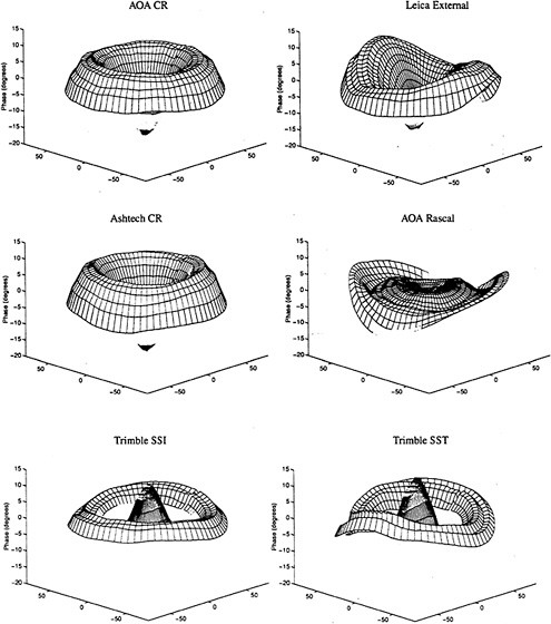
FIGURE 1 L1 phase center patterns are shown for several antennas (10 degrees of L1 phase is approximately 5 mm). Each of the sombrero plots shows zenith values in the center and 5 degree steps outward ending at 10 degrees above the horizon.
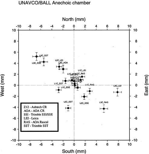
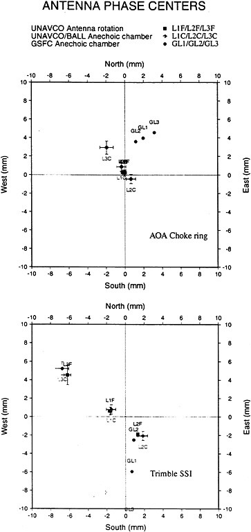
FIGURE 3 Horizontal phase center offsets derived from UNAVCO field antenna rotation tests (L1F, L2F, L3F), UNAVCO/Ball anechoic chamber tests (L1C...), and Goddard/Bendix anechoic chamber tests (GL1...).
The antenna rotation tests results shown here address only the phase center offset. However, it is possible to estimate phase patterns from field GPS data on short baselines (Mader and MacKay, 1995; Rothacher and others, 1995). This technique has the advantage that possible local site multipath and scattering effects can be accounted for. The results are, however, relative to a reference antenna for which a precise absolute calibration must exist (and the reference antenna must be setup to minimize multipath effects). We do not elaborate on these tests here since we have not compared them to chamber tests.
We found that L3 mixed-antenna, offset-corrected measurements with no tropospheric estimations were in error by 20 mm or less in the vertical (Figure 4, plus symbols on left panel) and by 1 mm or less in the horizontal. If hourly tropospheric estimations are included in the L3 solutions, the vertical error increases to as much as 87 mm for the Trimble SSI to Ashtech choke ring (Figure 4, plus symbols on right-hand panel).
Application of offset and pattern corrections reduces the vertical error for troposphere corrected Trimble SSI to AOA and Ashtech choke ring antenna mixes to 13 mm or less. The least successful application of the offset and phase center pattern corrections has been with the Trimble SST antenna where the residual error is as large as 50 mm.4
In general, mixed antenna baseline solutions show vertical errors of 12 mm or less without tropospheric estimation, and up to 50 mm with tropospheric estimation. This compares with 1 mm errors achieved with unmixed antennas on short baselines with no tropospheric estimations. The antenna mixing error has several possible sources. First, an anechoic chamber provides an ideal low multipath environment whereas observations in the field are influenced by local site conditions including multipath and monument effects.5 Second, differences in phase patterns between mixed antennas can be easily confused with tropospheric delay,
|
4 |
SST mixing results are available via ftp in unavco/pub/rec_test. |
|
5 |
We have shown, for example, that even with identical antennas, the use of low antenna mounts can seriously degrade vertical accuracy when tropospheric parameters are estimated. Nevertheless, it should be possible to map and correct for local multipath effects and any phase center pattern distortions resulting from the site antenna mount. This could be accomplished using a zero (or very low) multipath antenna with a well known antenna and mount phase center pattern. Variations in solutions between the zero and site antennas could be stacked for a number of days. Variations that persist in sidereal time could be used to correct for combined multipath and phase pattern effects. However, changes in local environment caused by snow, rain, plant growth, or modification of man-made structures could degrade the accuracy of this correction. |
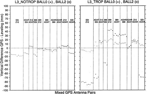
FIGURE 4 Summary of mixed-antenna vertical solution with offset corrections only (+ symbols) and offset plus phase center pattern corrections (o symbols). L3 solutions are shown with tropospheric estimation (right panel) and without tropospheric estimation (left panel). The columns, separated by vertical lines, show 10 different antenna mixes. Ground truth is indicated by the dotted line.
particularly at low elevation angles. These effects are described in the following section.
In order to investigate the effect of antennas heights on baseline accuracy, we conducted tests at Table Mountain where antennas could be easily mounted near to the ground over rod monuments set in concrete. Monuments were occupied with high (1.5 m) and low (less than 0.5 m) antenna tripod mounts with various GPS receivers and antennas. Baseline results using Trimble SSE GPS receivers and Trimble SST antennas with high and low antenna heights had vertical errors as large as 17 mm when tropospheric parameters were estimated. The horizontal components were not affected. The results of the antenna height tests are summarized in Table 1.6
|
6 |
Details of the high-low antenna tests are available via http://www.unavco.ucar.edu/docs/science/1995_ant_tests/tblmtn. |
TABLE 1 Vertical Solutions Using High (1.5 m) and Low (less than 0.5 m) Antenna Heights
|
Antenna heights |
No tropospheric estimation (rms in mm) |
With tropospheric estimation (rms in mm) |
|
low-low |
0.9 |
7.4 |
|
low-high |
1.3 |
5.6 |
|
high-high |
1.4 |
4.1 |
We found that multipath at the low antenna can be easily mismodeled as tropospheric delay. The multipath phase error generated by a low antenna can correlate to tropospheric delay for large intervals of elevation. Specifically, the L1 phase error for a low antenna is long period (more than 1 hour) and often correlates to tropospheric delay, particularly at low elevation angles (15 to 30 degrees) where multipath and tropospheric delays are strong. This can lead to vertical errors of several cm in daily solutions. Based on a simple multipath model and experimental results at Table Mountain, we conclude that: (1) GPS antennas should not be placed near the ground because the scattering from the ground causes low frequency multipath that can be mismodeled as tropospheric delay resulting in vertical errors as large as several cm, (2) measurements using GPS antennas mounted on tripods at 1.5 m height are generally more accurate because they are subject to high frequency multipath.7 It is important to note that for pillar monuments there is the possibility of an additional effect- scattering from the horizontal surface of the pillar immediately below the antenna (Elosegui and others, 1995). In this case the horizontal top of the monument is the main scatterer and the separation between the antenna and the top of the pillar is important, independent of the height of the monument above the ground. The scattering effect may be enhanced by the presence of a metal plate at the top of the pillar.
Multipath effects have been demonstrated to affect vertical accuracy in the high-low antenna setups described above. In addition, changes in multipath conditions, such as snow at the site, can affect vertical baseline solutions when tropospheric delays are estimated. Such an effect was found using two Trimble SSE antennas on a 55 m baseline with 1 m and 0.5 m antenna heights (Chris Alber, doctoral thesis in preparation). Vertical results for one day with snow cover and one without are given in Figure 5.
Each point represents the vertical baseline component solution from GIPSY processing using 24 hours of data and all satellites above the minimum elevation mask. The vertical baseline components for no-snow and snow are shown with and without stochastic tropospheric estimation. The results show a sensitivity at the 1 to 2 cm level to minimum elevation acceptance which is caused by multipath effects and is responsible for the errors and variability in vertical solutions from high-low antenna setups. Of note in this test, however, is the reversal in the sign of the effect when there is snow cover, indicating a large phase change in observed multipath. This effect is enhanced by the low height of one of the antennas. Similar effects were observed with 1-3 meter high monuments in the Swedish permanent network at least part of which was attributed to buildup of ice and snow on one side of the radomes over the antenna (Elosegui, and others, 1995).
For the highest accuracy applications such as vertical deformation studies or atmospheric sensing, multipath effects can be a limiting error source. Multipath effects can to some extent be minimized by careful site selection and installation, but can also be reduced by using an antenna with higher multipath suppression, and through software algorithms such as multipath stacking and prediction. One approach to improved antenna design is the addition of a 1 meter choke ring to the JPL/AOA choke ring antenna.8 This approach is attractive since it could be used to retrofit choke ring antennas currently installed in the IGS global network. Improvements in multipath reduction using a 1 meter ground plane with the AOA choke ring have also been demonstrated (Mader and Schenewerk, 1994).
|
7 |
High frequency multipath is not easily confused with tropospheric delay. |
|
8 |
Details of this design are available via http://www.unavco.ucar.edu/docs/science/geo_antenna. |
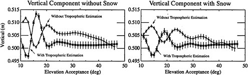
FIGURE 5 GIPSY processed vertical solutions are shown as a function of minimum satellite elevation acceptance for a day without snow and a day with snow, with and without tropospheric estimation. Each point represents a 24-hour solution using data from all satellites above the minimum elevation mask. Error bars show the formal solution error.
The anechoic chamber tests showed differences between the AOA choke ring and the Ashtech choke ring with radomes. Subsequent field tests have confirmed that antenna radomes significantly influence the vertical solutions. For example, using an Ashtech compressed styrofoam conical cover on only one end of a short baseline causes a 10 mm vertical error in the baseline vector when the tropospheric delay parameter is estimated. Preliminary results of an 1/8 inch thick acrylic dome cover shows a smaller, 2 mm vertical offset. UNAVCO is conducting further tests with a 1/4 inch acrylic cover used with AOA choke ring antennas at many IGS sites.
TABLE 2 Summary Of Antenna And Antenna Mounting Issues
|
Antenna Phase Center Variations |
||
|
PROBLEM |
STATIC POSITION ERROR LEVEL |
POSSIBLE SOLUTION |
|
Mixed Antenna Types |
up to 8 mm horizontal up to 90 mm vertical |
<3 mm horizontal chamber/insitu <10 mm to 30 mm anechoic chamber corrections <10 mm insitu GPS calibration (Mader and others, 1994) |
|
Like Antenna types with long baseline separation (“see” same satellite at different elevation) |
up to 0.015 ppm scale factor (Rothacher and others, 1995) |
Insitu GPS calibration, better anechoic chamber corrections |
|
Multipath and Scattering Effects |
||
|
PROBLEM |
ERROR LEVEL |
POSSIBLE SOLUTIONS |
|
Low antenna setup (<0.5 m) |
up to 20 mm vertical |
setup antenna >1.5 m from the ground, use lower multipath antenna |
|
Snow at site |
up to 20 mm vertical |
install higher or use lower multipath antenna; keep antenna clear of snow and ice |
|
Radomes |
2 mm to 15 mm vertical |
eliminate cover or use thinner, more microwave transparent cover (best to date is 1/8” acrylic give 2 mm vertical error) |
|
Pillar Signal Scattering |
up to 10 mm vertical |
microwave absorber under antenna;reduce cross-section of pillar; reduce metal plate under antenna; make pillar more microwave transparent (e.g. carbon fiber) |
Antenna mixing as well as site and antenna height dependent multipath effects may effect GPS accuracy at the level of a few mm to 10 cm (Table 2). Progress is being made by measuring and correcting for mixed antenna effects (using field and chamber data), by moving toward standard antennas,9 and by avoiding tropospheric estimation errors associated with low antennas.
Using antenna phase pattern and offset corrections derived from anechoic chamber tests, the accuracy for mixed Trimble SSI (patch antenna with removable ground-plane) and Ashtech and AOA choke ring antennas, with tropospheric estimation, is 12 mm or less in the vertical. Mixing results for other antennas are as high as 5 cm in the vertical. Additional work is needed to reduce antenna mixing errors down to the 1 mm level, to evaluate mixing of similar antennas made by different manufacturers (including different preamplifier designs), and to calibrate monument and cover effects.
Braun, J., C. Rocken, B. Stephens, W. Shiver, M. Exner, O. Rudd, C. Conquest, J. Johnson, and C. Meertens, Results of 1995 UNAVCO ARI Equipment tests, Trans, Amer. Geophys, Un., 76, November 7, 1995, p. F147.
Jaldehag, R. T. Kenneth, J. M. Johansson, J. L. Davis, and P. Elosegui, Geodesy using the Swedish permanent GPS Network: Effects of Snow Accumulation on Estiates of Site Positions, Geophys. Res. Let., accepted, 1996.
Elosegui, P., J.L. Davis, R.T.K. Jaldehag, J.M. Johansson, A.E. Niell and I.I. Shapiro, Geodesy using the Global Positioning System: The effects of signal scattering on estimates of site position, JGR preprint, 1995.
Mader, G.L. and J.R. MacKay, Calibration of GPS Antenna, draft publication, 1995.
Mader, G.L and M. S. Schenewerk, Groundplane Effects on Multipath and Phase Center Location and Calibration of GPS Antennas, Trans. Amer. Geophys. Un., 75, November, 1994, p. 171.
Rothacher, M. S. Schaer, L. Mervart, and G. Beutler, Determination of Antenna Phase Center Variations Using GPS Data, Paper presented at the 1995 IGS Workshop, Potsdam, Germany, May 15-17, 1995.
Schupler, B.R., and T.A. Clark, How different antennas affect the GPS Observable, GPS World, p. 32-36, Nov-Dec, 1991.
Schupler, B.R., R.L. Allshouse, T.A. Clark, 1994, Signal Characteristics of GPS User Antennas, Navigation, 41(3), 277-295, 1994.
Schupler, B.R., T.A. Clark, and R.L. Allshouse, Characterizations of GPS User Antennas: Reanalysis and New Results preprint, 1995.
|
9 |
JPL-designed choke rings with Dorne-Margolin antenna elements are now available form AOA and Ashtech and will soon be available from Trimble. |
Arthur Niell, Haystack Observatory
INTRODUCTION
Measurements made with GPS of site location, orbits, precipitable water vapor, and ionosphere total electron content should, within the uncertainties determined by the quantity and distribution of data used, have no systematic biases for changes in data selection or minimum elevation of accepted data. However, the dependence of estimates of the vertical position of the antenna and of the zenith delay of the atmosphere on minimum elevation angle, even when obtained using difference data to nearby identical antennas, are well documented and have been shown, at least for those cases studied, to be associated with near-field (within a few meters of the antenna) effects due to scattering off of the monument and/or snow (Elósegui et al, 1995, Jaldehag et al, 1996a,b). For widely separated but identical antennas the elevation dependence of the phase response of the antenna (Schupler, Clark, and Allshouse, 1994; Meertens et al 1996), if not taken into account, will produce a similar effect. The magnitude of these problems for the estimate of the height can be many centimeters.
Under controlled conditions the intrinsic phase response of the antennas (Meertens et al, 1996), or the differences of the responses of many antennas to one reference antenna (Mader and MacKay, 1995; Rothacher et al, 1995), can be measured and applied as corrections. However, even with ideal characterization of GPS antenna phase dependence by anechoic chamber measurements, the response of the antenna upon installation in the field will be altered by the electromagnetic environment. (The improvement in relative position on very short baselines that can be achieved using chamber measurements is discussed by Meertens et al (1996) in these proceedings.) Thus even over short baselines the estimates of the relative positions (primarily the vertical) of identical antennas can change by several centimeters for different observing geometries. While the effects of far-field (greater than a few meters) multipath can often be reduced by averaging over time, near-field (scattering) effects in general cannot. Furthermore, because of its low spatial frequency, scattering produces errors that vary systematically with elevation and is thus difficult to detect under standard single minimum-elevation-cutoff analysis. In this paper only the near-field problems will be addressed.
There are two reasons to reduce the elevation-dependent errors. Most obviously, better accuracy is desired. In addition, however, reduction of the elevation dependence serves also to decrease the sensitivity of the results both to changes in analysis procedures (such as raising the minimum elevation because of reduced SNR when AS was turned on) and to changes in the horizon mask, for example due to trees growing up or structures being erected. While elevation-independence does not imply accuracy, it hopefully reduces the character of the error to being simply a bias.
In this paper the extent of the elevation dependent height errors for both similar and dissimilar antennas will be illustrated; measurements of the effect of the Ashtech radome (itself a scatterer) on height estimates for a choke-ring antenna will be reported; and two potential solutions to the scattering problem for the specific geometry of the FLINN-type monument and antenna mount will be summarized.
The results reported in this section will illustrate the type of errors that may affect all geodetic results and measurements of precipitable water vapor, regardless of antenna separation.
Seven Allen Osborne Associates (AOA) TurboRogue receivers and four Ashtech Z-12 receivers were used for a two week campaign to measure precipitable water vapor in a region of diameter ~50 km centered on Haystack Observatory in Massachusetts in 1995 August, (A subset of these results was reported by Niell et al, 1995.) All of the TurboRogues and two of the Ashtechs had Dorne Margolin antennas with choke rings (hereafter called the choke-ring antenna). The Ashtech radome was used with the Ashtech choke-ring antennas. Two of the Ashtech receivers were connected to an older antenna model number 700718B. The ionosphere-free linear combination (LC) of the L1 and L2 phases were analyzed using GIPSY/OASIS-II version 4 (Webb and Zumberge 1995) in the point positioning mode. For the results reported here the position and zenith troposphere delay
|
1 |
© Massachusetts Institute of Technology, 1996. |
were estimated for each antenna in the frame of the satellite orbits and clocks determined for approximately thirty globally distributed sites.
The variation in estimated height, as the minimum elevation of included data was changed, of four of the antennas is shown in Figure 1. For correctly calibrated
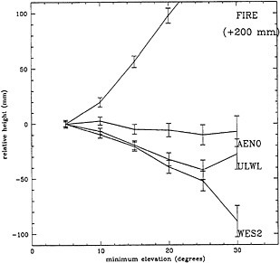
FIGURE 1 Apparent height relative to height at 5° as a function of minimum elevation of included data.
data the estimate would be independent of the minimum elevation. In this figure AEN0 is a AOA choke-ring mounted on a tripod on the peaked roof of a wooden house; WES2 is an AOA choke-ring mounted on a ~10 meter metal tower; ULWL is an Ashtech choke-ring antenna with radome mounted on a wooden tripod on a flat roof; and FIRE is the Ashtech navigation antenna (718B) mounted above the roof of a fire tower. (The sites were chosen for spatial distribution and not for geodetic appropriateness.) The error bars are one standard deviation in the height estimate based on one cm of phase noise; the uncertainties of the change in height with elevation for each site, which are obtained by differencing the covariances of the solutions, are smaller (Davis et al, 1985). It is clear that the two AOA choke-ring antennas could not use the same intrinsic phase corrections since the response of one (AEN0) is already independent of elevation. (If the anechoic chamber measurements are correct, this implies that the roof/tripod mount simply “undoes” the intrinsic elevation dependence of the phase.) Similarly, the Ashtech choke-ring/radome could not use the same corrections as either of the other choke-ring antennas. This is confirmed by Meertens et al (1996) who observed a difference in the phase response of the choke-ring antennas with and without the radome. The elevation dependence seems to be a characteristic of the combination of antenna type and mount since the same systems (e.g. choke-ring on tripod on peaked roof) at different locations have elevation dependencies that agree much better (within about one formal error in height) than with those of the different antenna/mount combinations. (The data supporting this conjecture are not shown.)
Although an elevation-dependent height estimate could also result from estimating the atmosphere delay with incorrect mapping functions, as shown by Davis et al (1985), these choke-ring sites are separated by less than 20 km and the mapping function errors are negligible for the comparisons being discussed.
From these data it can be seen that, while the repeatabilities of height measurements by GPS are ~1 cm, the accuracy can be no better than a few centimeters until the systematic errors are understood, even between the same model of antenna (compare AEN0 and WES2 in Figure 1; see also Elósegui et al., 1995). As a corollary, it should be clear that if measurements are made in separate occupations of a site, the same model of antenna should always be used, if possible, or else, if different types of antenna are unavoidable, both should be used on the same monument in one occupation to measure any change in position due to the difference in antenna type.
Short baseline measurements of the relative height of choke-ring antennas were made to evaluate the effect of using the Ashtech radome with the choke-ring antenna and to compare the geodetic equivalency of the Ashtech and AOA choke-ring antennas (Niell, King, McClusky, and Herring, 1996).
For a ten day period in 1996 January two Ashtech Z-12 and one AOA TurboRogue receivers were used with choke-ring antennas on wooden tripods separated by ~5 meters. The TurboRogue was connected to an AOA choke-ring antenna. One Z-12 was connected to an Ashtech choke-ring antenna for the period; on alternate days the Ashtech radome was installed. The other Z-12 was used with an Ashtech choke-ring for half of the time and with an AOA choke-ring for the remainder. The relative heights of the antennas were measured using a theodolite; two separate measurements agreed to ~1 mm.
The LC phases were analyzed using GAMIT (King and Bock, 1995) as they would be for a regional geodetic network. WES2, an AOA choke-ring antenna ~1 km
away, was used as the reference site. The position and a constant troposphere offset were estimated for each of the other three antennas.
The positive result is that interchanging the Ashtech choke-ring antenna (without radome) and the AOA choke-ring antenna gave differences in estimated position of less than 2 mm in all coordinates with uncertainties of ~1 mm. Less satisfactory were the effect of the radome and the comparison with the leveling.
The addition of the radome caused an apparent vertical displacement of the antenna by −15 ± 2 mm for data down to 15° elevation, and −5 ± 2 mm for data down to 5° elevation. Braun et al (1995) report a difference of −10 mm from the surveyed height difference for the same combination of antennas with a minimum elevation of 15°. Thus at the centimeter level the need to protect the antenna (from leaves, snow, seagulls, etc) may conflict with the accuracy requirements.
In the previous section the change in apparent height for different minimum elevations was shown to have different characteristics for the same antenna model in different environments. In this test we found, for the case of no radome on either antenna, a disturbing inconsistency between the GPS-measured height differences and the height differences measured with a theodolite (leveling). For the Ashtech-only site and the AOA-only site the GPS and theodolite measurements agree to 1 ± 2 mm. For the other site the GPS-measured heights of the AOA and Ashtech antennas agree to ~1 mm, but the difference of their height to both of the continuously-occupied choke-ring antennas disagrees with the leveling by 10 ± 2 mm. Thus within an area of 10 m height discrepancies of 10 mm exist for the same antenna types. Since the atmosphere is certainly not a factor over this distance, the problem is attributed to the near-field environment. (Although both the leveling and the analysis are also candidates for the 10 mm discrepancy, the leveling was repeated to 1 mm, and the files associated with the analysis have been carefully reviewed.)
The purpose of this illustration is to caution users that, although an antenna may be characterized by either or both anechoic chamber measurements and field measurements of their phase pattern (or phase pattern difference to another type of antenna), neither can be assumed to be applicable when the antenna is sited in the real world. Some possible procedures to reduce such effects are described in the next section.
One monument design, used at many IGS sites and often referred to as a FLINN-type monument, consists of a concrete pier of diameter 0.4 to 0.6 m with a metal plate imbedded in the top surface to provide the reference mark. The choke-ring antenna is supported ~10 cm above the plate. In short baseline (~2 meters) measurements relative to an identical antenna mounted on a wooden tripod the apparent height difference changed by 23 ± 3 mm from a 5° to a 40° elevation cutoff (Elósegui et al, 1995). Modeling the plate and mount as a simple reflector and using ray optics suggested that the systematic error of the phase residuals with elevation were consistent with a reflector approximately 10 cm below the antenna. To reduce the effect, microwave absorber was placed between the antenna and the plate. The apparent elevation change was reduced to less than 5 mm.
In a similar test MacMillan and Clark(1995) showed that filling the cavity between the antenna and the plate with balls of foil reduced the height change for minimum elevations of 10° to 40° from 32 mm to 13 mm.
The long term stability of such apparent improvements has not been tested. Microwave absorber may degrade when exposed to the sun and humidity for an extended period, thus producing an even less predictable error.
A better approach would be the design and production of an antenna and mount that did not have such problems. Some progress in this direction, obtained by increasing the diameter of the choke rings associated with the Dorne-Margolin antenna, has been reported by Meertens et al (1996). Since such extensions to the choke ring assembly might be achieved as an addition to existing antennas, this is a promising approach. However, the tests so far are limited.
Reducing the minimum-elevation-dependence of the estimated parameters to a negligible value does not guarantee that all bias has been removed. The absolute accuracy can only be obtained by comparison with a collocated perfect (or perfectly calibrated) system. Until such a system exists, sufficient tests should be conducted to ascertain the apparent level of sensitivity to changes in observation selection, especially the minimum elevation.
Based on the problems discussed above for the FLINN-type monuments and the Ashtech radomes, it is apparent that any new monument or antenna design should be evaluated before installation in the field. The following evaluation procedures are suggested for both proposed new monuments and existing sites.
-
-
Measure the height relative to 2 or more tripod-mounted antennas of the same type. Estimate the height and zenith troposphere delay differences using minimum elevations from 5° to 30°.
-
Compare with leveling among the antennas made with 1 mm accuracy.
-
-
Either by including the site in a global network or by using point positioning, estimate the height for minimum elevations from 5° to 30° (or perhaps for 7° and 23°) to assess any elevation dependence that may be common to all three antennas in part 1.
While these procedures do not solve the problem of antenna phases corrupted by local effects, their application may improve the quality of future mount designs as well as alert users to those sites which may be more susceptible to problems and which require greater consistency of use and analysis.
Acknowledgments. I thank Bob King for his constructive comments and suggestions.
Braun, J., C. Rocken, B. Stephens, W. Shiver, M. Exner, O. Ruud, C. Conquest, J. Johnson, and C. Meertens, Results of 1995 UNAVCO ARI Equipment Tests, Trans. Amer. Geophys. Un., 76, November 7, 1995, p. F147.
Davis, J. L., T. A. Herring, and I. I. Shapiro, A. E. E. Rogers, and G. Elgered, Geodesy by radio interferometry: Effects of atmospheric modeling errors on estimates of baseline length, Radio Science, 20, 1593-1607, 1985.
Elósequi, P., J. L. Davis, R. T. K. Jaldehag, J. M. Johansson, A. E. Niell, I. I. Shapiro, Geodesy using the global positioning system: The effects of signal scattering on estimates of site position, J. Geophys. Res., 100, 9921-9934, 1995.
Jaldehag, R.T.K., J.M. Johansson, J.L. Davis, P. Elósegui, “Geodesy Using the Swedish Permanent GPS Network: Effects of Snow Accumulation on Estimates of Site Positions”, submitted to GRL, 1996a.
Jaldehag, R.T.K., J.M. Johansson, B. O. Rönnäng, P. Elósegui, J.L. Davis, I.I. Shapiro, A.E. Niell, “Geodesy Using the Swedish Permanent GPS Network: Effects of Signal Scattering on Estimates of Relative Site Positions”, submitted to JGR - Solid Earth, 1996b.
King, R.W., and Y. Bock, “Documentation for the MIT GPS analysis software: GAMIT”, Mass. Inst. of Technol., Cambridge, 1995.
MacMillan, D. S., and T. A. Clark, Atmospheric Delays Estimated from an Array of GPS Receivers, Trans. Amer. Geophys. Un., 76, November 7, 1995, p. F145.
Maderand MacKay, Calibration of GPS Antennas, draft publication, 1995.
Meertens, C., C. Rocken, J. Braun, B. Stephens, C. Alber, R. Ware, M. Exner, and P. Kolesnikoff, Antenna Type, Mount, Height, Mixing, and Snow Effects in High-Accuracy GPS Observations, this volume.
Niell, A. E., A. J. Coster, F. S. Solheim, V. B. Mendes, P. C. P. Toor, and R. B. Langley, Comparison of the Measurements of Atmospheric Water Vapor by GPS, VLBI, WVR and Radiosondes During CONT95, Trans. Amer. Geophys. Un., 76, November 7, 1995, p. F145.
Niell, A. E., R. W. King, S. C. McClusky, and T. A. Herring, Radome effects on GPS height measurements with choke-ring antennas , Trans. Amer. Geophys. Un., May, 1996.
Schupler, B. R., T. A. Clark, and R. L. Allshouse, Signal Characteristics of GPS User Antennas, Navigation, 41(3), 277-295, 1994.
Rothacher, M.S., L. Schaer, Mervart, and G. Beutler, Determination of Antenna Phase Center Variations Using GPS Data, Paper presented at the 1995 IGS Workshop, Potsdam, Germany, May 15-17, 1995.
Webb, F. H., and J. F. Zumberge, An Introduction to GIPSY/OASIS-II, JPL D-11088, California Institute of Technology, Pasadena, California, July 17, 1995.
Frederick Solheim, Christopher Alber, Randolph Ware, Christian Rocken
University NAVSTAR Consortium
Two of the dominating errors in determination of the vertical coordinate in precise GPS geodesy are receiver antenna multipath and our inability to accurately model features in the wet troposphere. In an attempt to mitigate these error sources, we have implemented antennas with diminished gain at and below zero degrees elevation angle and pointed water vapor radiometers (WVRs). We have shown that applying these techniques improves repeatability on a 45 km baseline and for a short data set. It is thought that diminishing these error sources could likewise improve precise orbit determination.
To mitigate multipath signal from the antenna environment, we chose benign antenna sites. We further added choke rings to the existing Dorne Margolin choke ring antenna, bringing the overall diameter to 1 meter. These additional chokes were tapered downward at 10 degrees to retain gain at the horizon. This antenna is shown below mounted on the Table Mountain monument. An indication of the improvement due to these additional chokes is shown in the phase residuals below in Figure 2.
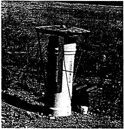
FIGURE 1 One meter choke enhancement, named “Mother,” to Dorne Margolin Choke ring antenna.
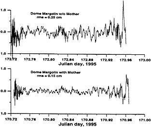
FIGURE 2 Short baseline (11 meter) carrier phase residuals for SV24, Trimble SSE with Dorne Margolin antennas. Upper data is with Dorne-Margolin antenna only, and lower panel is with 1 meter diameter Mother choke ring addition.
An example of the anisotropy of tropospheric water vapor is shown below in Figure 3. A water vapor radiometer was programmed to perform azimuth scans at a 30 degree elevation angle at Boulder Colorado. Skies were cloudless. A chronic 10 to 15% difference was observed from NW to SSE.
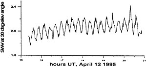
FIGURE 3 Azimuth scans of a WVR at 30 degree elevation under clear skies.
Such variations in the distribution of water vapor can induce error in the vertical dimension. WVRs were placed at each end of a 45 km baseline and programmed to measure the water vapor along the propagation path to each of the satellites in view.
Results of 9 days of baseline measurements with WVRs and enhanced antennas on this baseline are shown below in Figure 4 and are summarized in Table 1
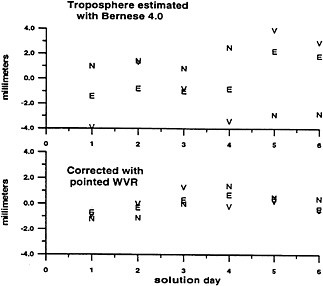
FIGURE 4 Coordinate scatter for 9 days of data, with and without pointed WVR corrections.
TABLE 1 Results on a 45 km Baseline
|
RMS repeatabilities (mm) |
north |
east |
vert |
|
Bernese 4.0 w/trop estimations (6 days) |
2.3 |
1.6 |
3.4 |
|
Corrected with pointed WVR (6 days) |
1.0 |
0.5 |
0.8 |
|
(9 days, some bad (incomplete) data) |
0.9 |
1.2 |
Estimation of the zenith water vapor burden above a GPS site has been demonstrated and is now becoming an operational tool. This estimation requires a surface barometric and temperature measurement, and its value to weather forecasts is enhanced by addition of a surface relative humidity measurement. The zenith vapor measurement represents some average of water vapor over the cone defined by the GPS elevation cutoff angle.
In a 1992 experiment to determine if commercial GPS receivers were sufficiently sensitive to perform occultation measurements from a low earth orbiter, a TurboRogue and Dorne Margolin antenna were placed at the 6000 level on Flagstaff Mountain above Boulder and were allowed to track descending satellites to signal loss. It was found that satellites could be tracked to about 1 degree below the physical horizon, but that ducting and multipath were significant problems. L1 and L2 p-code multipath, ionospheric delay and the time derivative of the ionospheric delay are shown relative to satellite elevation angle are shown in Figure 5. Note the severity of the multipath signature as the satellite descends below 1 degree.
This experiment also demonstrated that it might be possible to determine the water vapor burden along the propagation path from the carrier phase residuals, a local barometric pressure measurement, and an estimation or measurement of the zenith water vapor burden. This water vapor burden is called slant-path water vapor (SWV). In a primitive experiment we have compared multipath-corrected double differences in phase residuals as calculated with Bernese software with double differences measured by pointed WVRs. These results are shown in Figure 6.
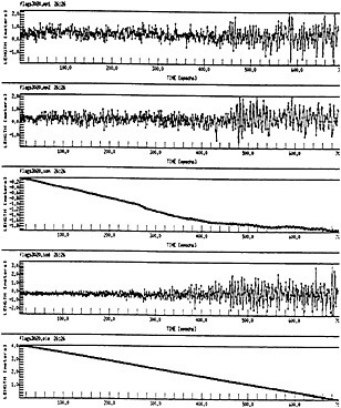
FIGURE 5 Results from low angle tracking experiment in 1992.
Although these preliminary results showed good agreement with WVRs, problems with ionospheric modeling at low angles due to ray bending and L1-L2 bifurcation, antenna multipath, and low signal to noise are anticipated for observations near the horizon. Good antenna sites and low multipath antennas will be required. Because ionospheric bending and bifurcation is aggravated at low angles, the proposed 3rd frequency (L5) could greatly improve ionospheric delay corrections.
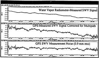
FIGURE 6 WVR double differences compared with Bernese double differences. Ordinate is in centimeters. Data are for SVs above 20 degrees elevation.
At any instant in time there are a number of GPS satellites in view. A typical snapshot of satellites in view is shown in Figure 7 (left). The satellite trajectories for a 24 hour period are shown in Figure 7, right.
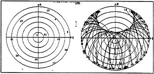
FIGURE 7 “Bull's-eye” plots of GPS satellite positions. Center is zenith, perimeter is horizon, 15 degree contour interval.
Forecast modelers estimate that the value of these SWV data as input to forecast models is high, even if we are not able to separate double differences into single path values. (cite McPherson and SV radiometer radiances here.....) The ability to give some definition to the spatial structure of water vapor, although integrated path values, is a strong constraint to forecast models. And if good measurements can be obtained at the horizon, sensing of tropospheric features to hundreds of miles beyond the horizon is possible. The magnitude of the value to meteorological forecasts is speculative, and simulations are needed.
As with the total zenith delay estimations currently being implemented, SWV could be implemented at numerous “targets of opportunity,” wherein adequate GPS receivers are installed for other purposes. Such implementations give multiple purpose to such existing and proposed GPS installations, and at relatively low cost. Some of the planned and existing FAA, Coast Guard, and other installations are shown in Figure 8.
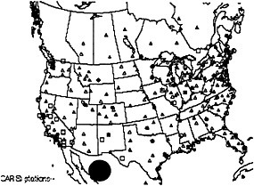
FIGURE 8 Existing and planned GPS receiver tracking sites in various networks. The circle over Chihuahua is 200km in radius, a distance at which a zero degree elevation angle observation would reach 2km above the surface of the Earth.
TABLE 2 Existing and Proposed GPS Installations.
|
NETWORKS |
CURRENT SITES |
PROPOSED SITES |
|
Regional |
100 |
400 |
|
National |
800 |
2400 |
|
International |
100 |
200 |
|
Totals |
1000 |
3000 |
Acknowledgments
Development of the low multipath antenna and the enhanced vertical accuracy experiment were supported under USAF AFGL Grant and peer reviewed NSF Grant.
The WVRs were loaned by Radiometrics Corporation.


