
1
Introduction
BRIEF DESCRIPTION OF THE GLOBAL POSITIONING SYSTEM1
The technical and operational characteristics of the GPS are organized into three distinct segments: the space segment, the operational control segment (OCS), and the user equipment segment. The GPS signals, which are broadcast by each satellite and carry data to both user equipment and the ground control facilities, link the segments into one system. Figure 1-1 briefly characterizes the signals and segments of the GPS.
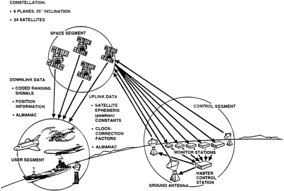
FIGURE 1-1 The three GPS segments. Source: The Aerospace Corporation
Space Segment
The GPS constellation consists of 24 satellites arranged in 6 orbital planes of 55- degree inclination, 20,051 kilometers (12,532 miles) above the Earth. Each satellite completes one orbit in one-half of a sidereal day and, therefore, passes over the same location on earth once every sidereal day, approximately 23 hours and 56 minutes. With this orbital configuration and number of satellites, a user at any location on Earth will have at least four satellites in view 24 hours per day
|
1 |
This description of the GPS is dervied from Appendix C of the National Research Council report, The Global Positioning System, A Shared National Asset — Recommendation for Technical Improvements and Enhancements. 1995. Washington, D.C.: National Academy Press. |
Operational Control Segment
The GPS OCS consists of the master control station (MCS), located at Falcon Air Force Base in Colorado Springs, Colorado; remote monitoring stations, located in Hawaii, Diego Garcia, Ascension Island, and Kwajalein; and uplink antennas, located at three of the four remote monitor stations and at the MCS._The four remote monitor stations contribute to satellite control by tracking each GPS satellite in orbit, monitoring its navigational signal, and relaying this information to the MCS. The four stations can track and monitor the whereabouts of each GPS satellite 20 to 21 hours per day. Land-based and space-based communications connect the remote monitoring stations with the MCS.
User Equipment
GPS user equipment varies widely in cost and complexity, depending on the receiver design and application. Receiver sets, which currently vary in price from approximately $135 or less to $30,000, can range from fairly simple devices that provide only basic positioning information to complex multichannel units that track all satellites in view and perform a variety of functions. Most GPS receivers consist of three basic components: (1) an antenna, which receives the signal and, in some cases, has anti-jamming capabilities; (2) a receiver-processor unit, which converts the radio signal to a useable navigation solution; and (3) a control/display unit, which displays the positioning information and provides an interface for receiver control.
Signal Characteristics and Operational Concepts
The GPS relies on the principle of “pseudoranging” to provide accurate positioning, velocity, and timing information. Each satellite in orbit transmits a continuous radio signal with a unique code that includes data about the satellite's position and the exact time the coded transmission was initiated, as kept by the on-board atomic clocks. A pseudorange measurement is created by measuring the distance between a user's receiver and a satellite by subtracting the time the signal was sent by the satellite from the time it was received by the user.
In general, a user's three-dimensional position can be determined by simultaneously measuring the ranges from a user's receiver to three satellites.. However, because the GPS satellites and receiver clocks are not perfectly synchronized, observations from a fourth satellite are needed to eliminate the receiver clock bias that is common to all the pseudorange measurements. Figure 1-2 illustrates the GPS pseudoranging concept.
Instead of transmitting one code on one radio signal (as described above), each satellite actually transmits two distinct spread spectrum signals that contain two different codes, the coarse acquisition (C/A) code and the precision (P) code. The C/A code is broadcast on the L-band carrier signal (known as L1), whose frequency is centered at 1575.42 MHz. The P-code is broadcast on the L1 carrier in phase quadrature with the C/A carrier and on a second carrier frequency (designated as L2), which is centered at 1227.60 MHz.
The L1 C/A-code provides free positioning capability to civilian and commercial users all over the world and is known as the Standard Positioning Service (SPS). The P-code is normally encrypted using National Security Agency cryptographic techniques, and decryption capability is available only to the military and other authorized users as determined by the U.S. Department of Defense. The encryption process, known as anti-spoofing (A-S), denies unauthorized access to the P-code and also significantly improves a receiver's ability to resist locking onto mimicked GPS signals, which could provide incorrect positioning information to a GPS user. P-code availability on both the L1 and L2 carrier signals through decryption capability provides authorized users with more accurate positioning and is known as the Precise Positioning Service (PPS).
Selective Availability and Other Positioning Errors
The accuracy of GPS is degraded for users of the SPS through a process known as selective availability (SA). SA is a deliberate degradation in GPS accuracy accomplished by intentionally varying the precise time of the clocks on board the satellites, which introduces errors into the GPS signal, and by providing incorrect orbital positioning data in the GPS navigation message. SA is normally set to a level that will provide 100-meter (2 drms) positioning accuracy to users of the SPS.2 The March 1996 Presidential Policy Directive on GPS states that it is the intention of the U.S. government to “discontinue the use of
|
2 |
SPS accuracy is normally represented using a horizontal 2 drms measurement, or twice the root mean square radial distance error. Normally, 2 drms can be graphically represented as a circle about the true position containing approximately 95 percent of the position determinations. |
GPS Selective Availability (SA) within a decade in a manner that allows adequate time and resources for our military forces to prepare fully for operations without SA.”3
In practice, there are several sources of error other than SA that can affect the accuracy of a GPS-derived position. These include unintentional clock and orbital errors, errors caused by atmospheric delays, multipath errors, errors caused by receiver noise, and errors due to poor satellite geometry. Many techniques and technical systems have been designed to improve the accuracy of the GPS SPS. These techniques range from the integration of GPS user equipment with other navigation/positioning systems, such as inertial navigation units, to the enhancement of GPS through differential and carrier tracking techniques.
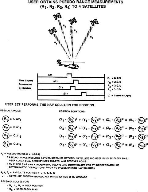
FIGURE 1-2 Pseudorange concept. Source: The Aerospace Corporation.
|
3 |
A fact sheet on this Presidential Policy Directive is included in Chapter 6 as an attachment to the paper titled “Civilian GPS Planning and Policy Making in the Federal Government. ” |
Differential GPS
The differential GPS (DGPS) method is based on knowledge of the highly accurate, geodetically surveyed location of a GPS reference station, which observes GPS signals in real time and compares their ranging information to the ranges expected to be observed at its fixed point. The differences between observed ranges and predicted ranges are used to compute corrections to GPS parameters, sources of error, and/or resultant positions. Differential corrections can be broadcast to GPS users, who can apply the corrections to their received GPS signals or computed positions. Corrections can also be stored for later analysis and dissemination. Differential techniques are used in many civilian applications to eliminate the effects of SA.
Carrier Phase Tracking
Instead of using C/A-code pseudoranging information to obtain a position solution, many GPS receivers also measure the L-band carrier signals. This technique, known as carrier phase tracking, works by determining which portion of the 19 centimeter L1 and 24 centimeter L2 carrier waves are striking the antenna at a given instant in time, thus revealing the phase of the received signals. With subsequent signal processing that includes squaring or cross-correlating the carrier waves, carrier phase tracking can produce very precise measurements, sometimes as good as 1 to 5 millimeters. Thus, the technique is valuable for high-performance applications. The difficulty with using carrier phase tracking is determining the exact number of carrier wave cycles along the path from the GPS satellites to the receiver's antenna, also known as ambiguity resolution. For static positioning, this can be accomplished by various techniques that include knowing the approximate location of the antenna and simultaneously tracking signals from all satellites in view of the antenna. The process is more difficult for real-time dynamic positioning but can still be used. Because GPS receivers using this technique give civilian users access to both the L1 and L2 frequencies without accessing the codes transmitted on L1 and L2, they are often referred to as “codeless” receivers.
GPS AS A TOOL FOR THE EARTH, OCEANIC, AND ATMOSPHERIC SCIENCES
A variety of federal, state, county, and public sector organizations and their counterparts in other countries are establishing or planning to use networks of GPS reference stations, utilizing both differential and carrier phase tracking techniques, for either real-time navigation or post-processed positioning. The use of GPS networks for research in the Earth and oceanic sciences has been well established for a number of years. For example, the National Aeronautics and Space Administration (NASA) and other organizations from various nations have established the International GPS Service for Geodynamics, a network of more than 140 continuously operating reference stations, data centers, and analysis centers that collectively support geophysical and geodetic research, such as the measurement of active tectonic processes, ice sheet movements, changes in sea level, and variations in the Earth's rotation.
Ground-based GPS networks and receivers on board low Earth orbiting (LEO) satellites are also being used to sense the atmosphere by measuring the delay encountered as GPS signals pass through the troposphere and the ionosphere. Water vapor measurements made with GPS-based remote sensing may be important for weather forecasting and research on global climate change.


