
5
Communications, Computers, Displays, and Sensors
The communications, computers, displays, and sensor systems for the dismounted soldier will provide the soldier with information about location and surroundings, evaluate tactical intelligence, assist in targeting, and permit voice and data communications with squad members and field operations centers. These systems will be introduced with modest capabilities in the fully developed Land Warrior equipment and will evolve to higher performance levels to meet increasing demands. Unfortunately, the Land Warrior systems will require a large amount of electric power. Table 5-1 lists estimated power requirements for the communications, computing, display, and sensor functions of the Land Warrior system.
The data in Table 5-1 clearly indicate that most of the energy dissipated in the Land Warrior system will be associated with the radios and computers to be carried by soldiers and, therefore, that the electronics associated with communications and computing functions afford the greatest opportunities for energy savings. The challenge for future Land Warrior systems and successor systems will be to reduce electrical energy consumption while increasing performance to meet projected increases in communications bandwidth, data file sizes, and computational performance.
It is important for the Army to recognize that the electronics industry faces similar challenges in commercial markets and is developing a wide range of low power technologies and design methodologies that are directly applicable to portable military equipment. These emerging technologies will have such a dramatic impact on the energy consumed in performing digital electronic functions—reductions anywhere from a factor of 10 to a factor of 50 are possible—that the Army must either use them or risk fielding equipment that is markedly inferior to commercially available equipment.
Specifically, industry is being driven to increase the performance and simultaneously improve the battery life of commercial products, including portable communications equipment, such as cellular phones and pagers; portable computing devices, such as laptops, palm-tops, and pocket organizers; and portable audio and video equipment, such as camcorders, audio tape and CD
TABLE 5-1 Power Requirements of the Land Warrior System by Function
|
Function |
Operating Power |
|
Communications |
|
|
Soldier radio |
7.4 W |
|
Squad radio |
14.0 W |
|
Computer |
14.8 W |
|
Displays |
|
|
Hand-held flat panel display |
6.4 W |
|
Helmet-mounted display |
4.9 W |
|
Integrated sight module display |
2.6 W |
|
Sensors |
7.9 W |
players, and portable television sets. Low power technologies and design methodologies are being developed in the following general categories:
-
low-voltage semiconductor processing technology
-
power optimizing hardware design methodologies
-
power optimizing software design methodologies
This chapter reviews commercial trends that are driving the development of low power technology. It describes how new low power technologies and design methodologies are being used to design commercial products, details the magnitude of improvements in performance, and projects improvements that may be possible in the future. Subsequent sections contain detailed studies of the communications, computing, sensors, and display equipment to be used by Land Warrior, along with descriptions and assessments of enabling technologies.
TRENDS IN DESIGNING COMMERCIAL PORTABLE EQUIPMENT
Suppliers of portable consumer electronics face conflicting demands of increasing performance while decreasing power drain1 in order to provide longer battery life. Two of the best examples are cellular telephones and laptop computers. Figure 5-1 plots the complexity of high performance microprocessors by the year each device was introduced. The graph shows that microcomputer complexity has increased by a factor of ten every seven years, following Moore's
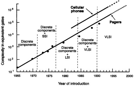
Law of integrated circuit complexity (see Chapter 4). Figure 5-2 plots the complexity of radio pagers and cellular phones by year of introduction. Predictably, it shows that the complexity of these products is driven by the complexity of integrated circuits; these slopes also follow Moore's Law. A frequently unrecognized implication of the data in Figures 5-1 and 5-2 is that, because power drain tends to track complexity, the power requirements of semiconductor products have also increased exponentially. The thousand fold increase in complexity over the past 25 years has driven circuit complexity to the point that power drain has become a major problem facing the electronics industry.
The power dissipation of a digital logic integrated circuit is determined by several factors, including the operating voltage of the circuit, the complexity of
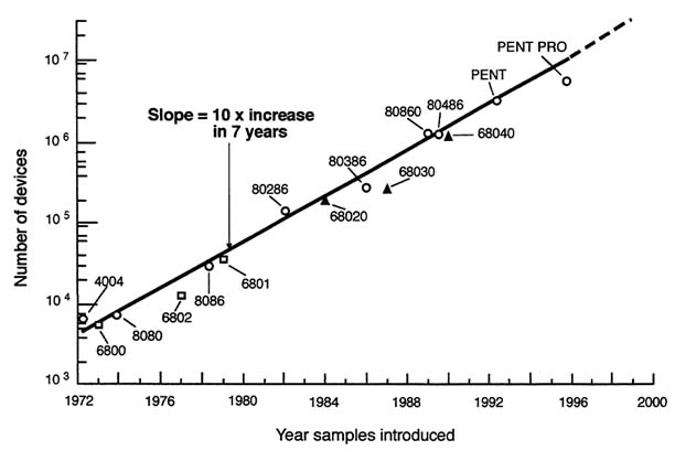
FIGURE 5-1 Complexity of microprocessors by year of introduction.
Notes
SSI = small scale integration
LSI = large scale integration
VLSI = very large scale integration
FIGURE 5-2 Complexity of cellular phones and pagers by year of introduction.
the circuit, the operating frequency of the elements of the circuit, and the speed-power product of the process used to fabricate the circuit. For a circuit in which all of the logic elements operate at the same frequency, the relation of these parameters can be expressed as:
Pd ~Kp·C·F·SP (1)
Pd = power dissipation of the circuit. Kp = a process and supply voltage dependent constant. C = the complexity of the circuit in equivalent gates. F = the operating frequency of the circuit. SP = the speed-power product of the semiconductor process.
Thus, two major factors besides complexity influence power drain: the operating frequency of the logic and the speed-power characteristics of the semiconductor process.
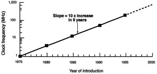
FIGURE 5-3 Operating frequency of high-end microprocessors used in desk-top computers by year of introduction.
Figure 5-3 plots the operating frequency of the high-end microprocessors used in desktop computers. Performance, measured by maximum operating frequency, has increased steadily, by a factor of ten every nine years. The performance of other digital logic functions, such as digital signal processors and numeric coprocessors, has followed a similar trend.
This performance trend is well known and has been one of the main reasons for the success of the personal computer and workstation industries, as well as most consumer electronics products. The frequently unrecognized implication of this trend has been an exponential increase in the inherent energy consumption of very-large-scale integrated (VLSI) circuits. Taken together, the data in Figures 5-1 and 5-3 indicate that two of the factors in Equation (1), complexity (C) and frequency (F), have been increasing at a combined exponential rate of a factor of 100 every eight years.
Figure 5-4 plots the speed-power efficiency of several bipolar and CMOS (complementary metal-oxide semiconductor) integrated circuit processes by the year they were first used for commercial production. Speed-power efficiency has improved by a factor of ten every eight years. Although this improvement closely tracks the increase in complexity of VLSI chips, it does not compensate for the combined rate of increase in complexity and performance. Indeed, the net combined rate of change in the three parameters in Equation (1) is a tenfold increase every eight years.
The semiconductor industry has been rapidly approaching a situation in which power will become a major barrier to further improvements in complexity and performance. The problems include: poor battery life for portable equipment;
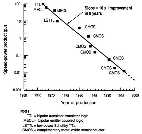
FIGURE 5-4 Improvement in the speed-power characteristic of integrated circuit processes by year of introduction.
heat dissipation and cooling problems for high-performance chips and systems; and reliability problems associated with elevated operating temperatures of semiconductors.
Until recently, the electronics industry has not paid much attention to power drain and its associated problems. This situation is highlighted in Figure 5-5, which shows the power drain per million instructions per second (MIPS) of the leading commercial microprocessors through the year 1993. The chart shows that there was essentially no reduction in the power drain of these products through 1993. The power efficiency on a mW/MIPS basis actually degraded over time. In fact, the first samples of the Pentium™ processor reportedly overheated because they exceeded the dissipation limit of their packages!
The products shown in Figure 5-5 are high-end microprocessors designed for desk-top applications, for which power drain was not considered an important design parameter. The only power consideration was that the devices should not exceed the heat dissipation of the planned packaging. In the early 1990s, however, cellular telephones, personal digital assistants, laptop computers, camcorders, and other portable products began to sell in significant numbers. Battery life became
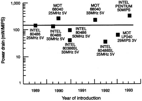
FIGURE 5-5 Power drain versus performance for microprocessors used in desk top computers from 1989 to 1993.
an important design issue for these products, and new microprocessor designs aimed at optimizing performance per unit of power drain appeared on the market.
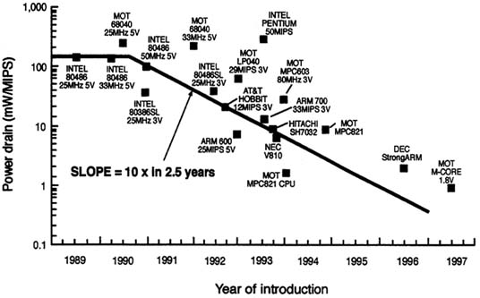
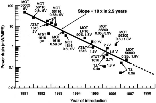
The improvement in the performance of several products is shown in Figure 5-6. Here, products such as the ARM™ central processor unit (CPU) from Advanced RISC (reduced instruction set computer) Machines and the Hobbit™ from AT&T, showed significantly better performance per unit of power (by a factor of 25 in the case of the ARM processor). Subsequent products from NEC and Hitachi, together with process improvements and design changes that allowed low-voltage operation, have pushed the power per MIPS figure down to 1 mW. One of the most startling aspects of the data in Figure 5-6 is that the power required by microprocessors designed for portable, battery-operated devices is decreasing at the astounding rate of a factor of ten in two-and-one-half years. To show that this is not an isolated case, Figure 5-7 plots the same performance for communications-oriented DSPs and shows that they are being improved at the same rate.
The recent improvements in microprocessors and general-purpose programmable DSPs are being driven by a number of design and implementation changes:
-
First and foremost, power drain is being treated as a key design parameter.
-
Architectures are being optimized for each application. In the case of microprocessors, small, power efficient RISC CPUs are being developed and used for portable applications over the larger complete instruction set computer (CISC) architectures, such as the Pentium™, that are used in desk-top computers. For example, the ARM™ RISC CPU contains 35,000 transistors, compared with 187,000 in the PowerPC™.
-
Low power design techniques are being developed and used with the same priority previously given to maximizing speed and other performance parameters. Examples of these techniques include removing clock signals from unused functions, selecting devices that are sized to optimize speed and power, and selecting the lowest function operating speeds necessary to complete tasks.
-
Operating voltage is being lowered to the lowest practical value.
Of all the system parameters affecting power drain, changes in operating voltage have the greatest impact. As illustrated in Figure 5-8, the power drain of the basic complementary logic gate structure is proportional to the square of the system operating voltage. This relationship yields the normalized power drain versus operating voltage slope shown in Figure 5-9, which indicates that a 30-fold reduction in logic power could ideally be achieved by lowering the supply voltage from 5.0 V to 0.9 V.
In practice, it is difficult to implement high-performance logic functions that operate at 1 V today, but substantial power drain reductions have been achieved by moving from 5.0 V to 3.3 V for portable computer systems and cellular phones (a factor of 2.3) and to 2.0 V for consumer audio products (a factor of 6.25). These voltage changes have been achieved by using fairly straightforward modifications of the basic CMOS fabrication processes used in the early 1990s. However, industry is working toward advanced low-voltage
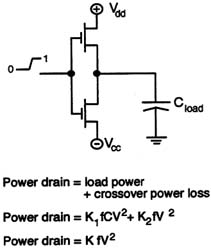
FIGURE 5-8 Basic complementary gate structure.
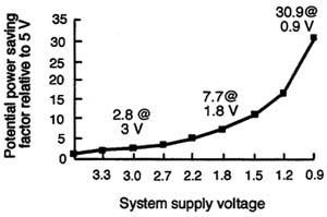
FIGURE 5-9 Power savings of low-voltage logic operation.
semiconductor processes that can implement high-speed logic at even lower voltages, and microprocessors and DSPs that provide more than 250 MIPS at 1.5 V should be commercially available by the year 2000.
Manufacturers of portable equipment, at the product level, are using many of the techniques used by component-level designers, as well as several system-oriented methodologies that significantly reduce power drain. These techniques include:
-
System supply voltages are being lowered, and the operating voltage of major subsystems is being selected to optimize both the energy efficiency and the performance of the element. DC-DC converters (Chandrakasan et al., 1994) are often used to provide different supply voltages for key subsystems as shown in Figure 5-10. In camcorders and cellular phones, for example, a ''high" voltage battery (typically 6 V) directly supplies analog functions, such as RF power amplifiers or auto-focusing motors that operate best at 5 V, while high-efficiency DC-DC converters are used to supply 2 or 3 V to digital elements. The overall effect is a significant reduction in power drain compared with schemes that operate all functions at the same supply voltage or use loss regulators to generate the lower voltages.
-
System architectures are being developed to lower power drain. Examples of this approach include: function-level designs that use parallel logic elements to reduce the operating frequency of each element and the total power drain of the function while maintaining overall performance; and, system and function designs based on new algorithms that reduce power drain.
-
The implications of implementing functions in hardware versus software are being studied carefully, and many functions that have been software-based are being implemented in hardware to reduce power drain. One example of this is the 50-fold reduction in power achieved when the trellis decoding function used in cellular telephones was switched from software to hardware.
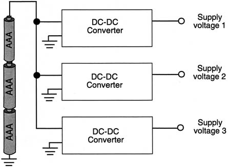
FIGURE 5-10 Power distribution used in portable products.
-
Commercial portable product designs are quickly adopting ASIC (application-specific integrated circuit) and system-on-a-chip design methodologies (explained in Chapter 4). These methodologies make many of the techniques described above practical by providing the means for implementing them. The reduction of supply voltages is facilitated, for example, because in the ASIC environment elements can be designed to operate at optimal voltages; the same low-voltage performance may not be duplicated using commercial components.
The single chip environment readily accommodates the implementation of architectural level changes with the greatest potential impact on power drain. The single chip environment eliminates the large interconnect capacitances associated with multichip systems. In high speed systems, driving signals across interchip connection paths requires significant power; in many computer systems this accounts for most of the system power. This point is highlighted in Figure 5-11, which plots the power drain associated with single-line and eight-bit bus
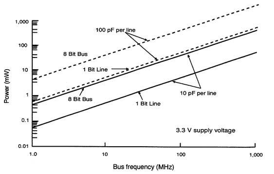
FIGURE 5-11 Power dissipation due to system interconnections.
interconnects as a function of frequency for line capacitances of 10 picofarads (pF) and 100 pF. The 10 pF load is typical of single-chip systems; the 100 pF load is typical of printed circuit board systems. The data show that, at high frequencies, power lost in the system interconnect can actually exceed power drain in the computer core. This has motivated commercial equipment designers to use highly integrated system chips to minimize losses associated with multichip system implementations. The Army will have to follow suit to reduce losses associated with printed circuit board interconnects in its high frequency systems.
Taken together, the net effect of the design and methodology changes discussed in this section has been to reduce substantially the power drain of key component-level functions, such as microprocessors and DSPs, and of system-level products, such as cellular telephones, camcorders, and portable computing devices. At the component level, the power drains of microprocessors and DSPs have been reduced by a factor of 100 over the past five years, and further improvements of at least a factor of five are anticipated as new low voltage semiconductor processes move into production. At the product level, improvements of a factor of ten have been achieved, and further improvements of at least a factor of ten are anticipated as the new low power components and processes are introduced commercially.
Examples of product improvements made possible by these advances abound. Talk time of cellular phones has improved from 20 minutes for very large
"brick" phones to more than 150 minutes for pocket-size phones. Battery life of popular WalkmanTM portable devices has improved from two hours when they were first introduced to more than 20 hours with recent designs. The Army will have to find a way to apply these technology improvements to the design of future equipment. Otherwise, a future enemy may be able to buy more energy-efficient equipment with better capabilities in a local electronics store.
The remaining sections of this chapter review power performance and energy characteristics of the Land Warrior systems communications, computers, displays, and sensors as they relate to the best commercial technologies. Like the electronics in commercial products, the electronics associated with Land Warrior systems have great potential for energy savings.
COMMUNICATIONS
The radio communications-electronics to be used by the dismounted soldier as part of the Land Warrior system consist of a soldier ratio that will be carried by every soldier in the squad and a separate squad ratio carried by the squad leader. The soldier radio will be used for intrasquad communication and is designed to have a communications radius of 1 km. The squad radio will be used for intersquad and squad-to-headquarters communications, with transmission ranges of from 1 to 5 km. Both radios will be linked to the Land Warrior computer.
The two radios will be compatible with each other to the extent that the squad radio must be able to route intersquad voice and data traffic from soldier radios to higher command levels. In part, this will be accomplished using existing combat net radios, but the vision of the digitized battlefield is to link the hierarchy of soldier and squad radios to high-speed, wide-bandwidth communications channels connected with higher levels of the command hierarchy. The resulting network would be able to collect and distribute tactical information and thereby increase situational awareness at all levels.
Power Objectives
The soldier radio will be a small, lightweight, low power voice and data radio that uses standard Army signaling protocol. It will be used to provide voice and data communications among members of the squad. Although the design is not final, power goals for the soldier radio in the Land Warrior system are to provide reliable voice and data communications using 1.4 W in the standby, or listen, mode and 6.0 W in the transmit mode.
The squad radio will be a voice and data radio compatible with the single channel ground airborne system (SINCGARS) combat net radios already in Army
service. To ensure compatibility with SINCGARS, it will be necessary for the squad radio to include the following features:
-
frequency modulation (FM) operation in the very high frequency (VHF) band from 30.000 to 87.975 MHz
-
single channel and frequency hopping modes of operation
-
25 kHz channel spacing for 2,320 operating frequencies
-
support for analog voice and data communications
-
digital data communications rates up to 16 kbps
-
support for encrypted secure communications
It is well known in the Army that the SINCGARS radio is unable to support the high data rates needed for the digitized battlefield. The peak SINCGARS data rate is only 16 kbps, but megabits per second of channel capacity are needed to transport real-time images, video, and other tactical data. For this reason alone, the squad radio will have to be much more than a scaled-down version of the SINCGARS man pack radio set.
Transmitter Energy Consumption
Transmitters account for most of the energy consumed by radios. For a radio to be energy-efficient, practically all of the energy consumption should occur in the final amplifier stage, and the antenna should be matched to the output to minimize energy losses at the antenna interface. In both soldier and squad radios, the transmitting power must be consistent with operation at high data rates. Figure 5-12 plots on a logarithmic sale the radiated power for a hand-held transmitter to communicate reliably at 75 MHz as a function of distance and data rate for a particular set of operating conditions. The data shows that, even though a radiated RF (radio frequency) power of 0.6 W will operate at 16 kbps at 1.5 km, the power must be raised to 6 W to communicate at 160 kbps, and to 60 W at 1.6 Mbps. Clearly, any data rate above a few hundred kbps is incompatible with the reduced size and weight goals of the Land Warrior radios.
The data on radio propagation path losses presented in this section indicate that significant power and energy are required to communicate over the required distances for the soldier and squad radios. These power and energy levels are set by the path losses associated with propagation across difficult terrain in adverse weather conditions and cannot be reduced without fundamentally altering the basic architecture of the radio communication network used in the battlefield. The significance of the network architecture for providing reliable transmission as well as for meeting energy goals is discussed in detail in Chapter 6.
Subsequent sections of this chapter will show that the energy consumption of the other functional elements of the Land Warrior system can be reduced

FIGURE 5-12 Radio frequency power required for reliable communications.
significantly; but radio systems are destined, by basic laws of physics, to use the most power.
COMPUTERS
The current design for the Land Warrior computer is based on commercial personal computer (PC) technology. Like the Army, commercial PC manufacturers have focused primarily on performance and been less concerned with reducing energy consumption. Only modest improvements in the power requirements of commercial PC-based systems have been made. Power drain has been reduced in some PC-based systems similar to the Land Warrior computer, however, and additional energy savings can be achieved without sacrificing performance.
Land Warrior Computer
The Land Warrior computer prototype is based on a commercial 50 MHz 486 processor and uses a variety of plug-in modules to add functions to the basic unit. These modules, linked via industry-standard PCMCIA (personal computer memory card international association) interfaces, include the global positioning system (GPS) receiver and the soldier (intrasquad) radio. The software runs on a standard general-purpose operating system defined by the defense information infrastructure common operating environment (DIICOE), and both the software and the operating system are stored on a hard disk.
TABLE 5-2 Power Requirements of the Land Warrior Computer
|
Function |
Cumulative Peak Power (W) |
Function Operating Power (W) |
Standby (Alert) Power (W) |
Operating Duty Cycle (%) |
Average Operating Power (W) |
|
Processor card |
4.3 |
3.6 |
0.5 |
90 |
3.88 |
|
Hard disk |
3.0 |
1.9 |
0.6 |
10 |
1.02 |
|
Flash memory |
1.1 |
0.9 |
0.0 |
1 |
0.01 |
|
RS232 #1 |
0.8 |
0.7 |
0.00 |
40 |
0.33 |
|
RS232 #2 |
0.8 |
0.7 |
0.00 |
10 |
0.08 |
|
Tactical communications interface module (TCIM) |
1.1 |
0.9 |
0.0 |
20 |
0.21 |
|
Video processor |
2.0 |
1.7 |
0.0 |
15 |
0.30 |
|
Audio ampere/processor |
3.0 |
2.5 |
0.20 |
40 |
1.33 |
|
Information security |
1.2 |
1.0 |
0.18 |
10 |
0.33 |
|
Power management |
0.5 |
0.4 |
0.00 |
100 |
0.48 |
|
Motherboard |
0.2 |
0.2 |
0.0 |
15 |
0.24 |
|
Keyboard |
0.1 |
0.1 |
0.0 |
5 |
0.01 |
|
Remote input pointing/positioning device (RIPD) |
0.1 |
0.05 |
0.0 |
90 |
0.05 |
|
Synchronous serial I/O |
0.2 |
0.15 |
0.0 |
0 |
0.00 |
|
TOTAL |
18.4 |
14.8 |
1.48 |
— |
8.27 |
Table 5-2 lists the estimated power requirement for the major computer subsystems. The data reflect a 90 percent duty cycle factor for the computer because the Land Warrior architecture uses the computer as a central processing hub for other elements of the system, including the radio—a configuration that precludes the use of conventional power management techniques because the computer must continually monitor the radio for incoming messages.
Because the soldier computer must meet the standardization requirements of the DIICOE, each soldier is technically obligated to carry 100 megabytes of operating system and application software. This use of a general-purpose operating system increases system complexity because more random access memory (RAM) and program memory and a higher system clock rate are needed to store and execute the operating systems and applications, thereby increasing energy consumption. The hard disk drive used to store operating system and programming files itself consumes considerable energy.
In addition to increased energy consumption, using complex software generates logistical problems associated with managing software updates and installing software. General-purpose operating systems are also prone to crashing and leaving other systems dependent on the computer inoperable until the computer is rebooted.
General-Purpose Computing Trends
Computer systems are typically compared using two classes of metrics: capacity and performance. Capacity is how large a component is or how much information it can store. Performance is measured in functions per unit time (often referred to as bandwidth or throughput) or, conversely, the time needed to complete a specific function (referred to as latency). Recently, ease of use has become a major differentiator between computer systems and, hence, represents a third class of metrics.
Metrics for measuring hardware capacity and performance directly reflect the state of technology and are associated with the attributes of common elements of a computer system. Six metrics are commonly used to measure computer performance—processor speed, the size of the RAM, the capacity of the disk memory, the size of the display, the bandwidth of the network communications link, and the distance the computer can roam from a network access point. Two other metrics, energy consumption and physical size, are also becoming important as computers become more mobile.
Table 5-3 summarizes the current range of values for these eight metrics for three classes of computer systems: high-performance workstations, laptop computers, and personal digital assistants (PDAs), also known as palm-top computers. In the table, processor performance is measured in MIPS (millions of instructions executed per second); capacity-related parameters are measured in information units, such as bytes or pixels; communications throughput is measured in bits per second; energy consumption is measured as the reciprocal of the power in kilowatts; and the physical size is presented as the reciprocal of the product of the weight times the volume of space occupied. Note that for all of these metrics, larger numbers are associated with higher performance.
The three columns in Table 5-3 include a contemporary workstation (an anchored, unmovable system), a contemporary laptop computer (a luggable system), and a palm-top computer (a portable, pocketable system). Siewiorek, Bell, and Newell (1982) considered the concept of computer class in attempting to integrate many details of computer systems into an overall evaluation, grouping similarly evaluated systems together. They observed that computer classes differ in physical dimensions and price by roughly 1.5 orders of magnitude (approximately a factor of 30). As each computer class evolves, new members of the class are expected to have increased capacity and functionality. Improvements in technology increase the capacity and functionality of a class. Thus the
TABLE 5-3 Capacity and Performance of Computer Systems
|
Components |
Units |
Workstation |
Laptop |
Palm-top/PDA |
|
Processor |
MIPS |
400 |
150 |
15 |
|
Random access memory (RAM) |
millions of bytes |
128 |
16 |
4 |
|
Disk memory |
millions of bytes |
4,000 |
400 |
— |
|
Display |
millions of pixels |
1 |
0.307 |
0.115 |
|
Network communications |
millions of bits/second |
100 |
10 |
0.0338 |
|
Distance |
meters |
— |
100 |
10,000 |
|
Energy consumption |
1/kW |
5 |
125 |
1,000 |
|
Physical size (1/weight x volume) |
1/kg x m3 |
3 |
200 |
6,000 |
boundaries of various attributes can be considered to be increasing with time as depicted in Figure 5-13, where each metric is plotted on a logarithmic scale.
Technological advances have created three successive computer classes with each succeeding class exhibiting functionalities identical to its predecessor. The three classes of computers have followed practically the same evolutionary path as capacity and functionality have increased. The newer computer classes have benefited from the evolutionary process of older classes, adapting to proven concepts quickly whereas the older classes required a trial and error process. Siewiorek, Bell, and Newell (1982) observed that computer classes tend to lag behind each other by approximately five years. Thus the palm-top computer of today could be considered to have approximately the functionality of a laptop of five years ago or a workstation of ten years ago. There is little doubt that the palm-top will have the attributes of today's high-performance workstation by the year 2007.
Customized and General-Purpose Architectures
A new class of "wearable computers" is emerging. Wearable computers weigh only a few ounces, operate for months or years on a single battery, and have esthetically pleasing shapes that can adorn various parts of the body. Pagers
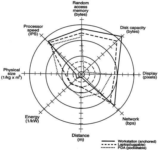
FIGURE 5-13 Computer system attributes. Each axis is a logarithmic scale with each mark representing a factor of 10 and each circle representing a factor of 1,000 (i.e., the value of the four circles are: one; one thousand; one million; and one billion from the inner most circle to the outer most circle).
and electronic watches (incorporating calculator and memory storage functions) are the first examples of the wearable class of computers. This new class can be expected to have at least the functionality of today's laptops by the year 2007.
General-purpose computing architectures achieve their general-purpose attributes at the expense of system complexity and energy consumption. Appendix E describes the evolution of wearable speech-operated computers from general-purpose laptop computers. The Navigator series of wearable computers, developed under DARPA sponsorship, demonstrates that it is possible today to implement software-driven systems with COTS (commercial-off-the-shelf) PC components, with one-half to one-fifth the energy consumption of a general-purpose computer.
Another DARPA project relevant to Land Warrior, a customized multimedia terminal using ''embedded" systems, is described later in this chapter and offers improvements in energy efficiency by a factor of 100. Both cases illustrate what can be achieved in energy efficiency when performance is optimized for target applications and general-purpose characteristics are restricted.
Embedded systems are computer-based systems designed to provide specific required functions. They can be significantly less complex than general-purpose computer systems, and, by not requiring adherence to a complex complement of operating and application software standards, they can take advantage of a wide range of energy conserving techniques.
Industry experience with high performance portable consumer electronics, such as cellular telephones and camcorders, has shown that embedded computer systems can operate at 10 to 100 times less power than systems based on conventional general-purpose computers. Figure 5-2 plots the complexity of pagers and cellular telephones. The complexities of these entire systems approaches those of the microprocessor alone in general-purpose systems (see Figure 5-1), and yet they have power drains that are 100 to 1,000 times lower than those of general-purpose microprocessors. In addition to this power advantage, they can also be sized to the application by restricting performance to whatever is required to perform specific tasks.
Embedded systems are composed of one or two chips upon which a processor core is integrated with memory and with special-purpose processing elements, such as digital signal processors. Although microprocessors targeted for PC applications show little improvement in energy consumption, processors designed for embedded systems, such as the ARM™ processor (see Figure 5-6), are continuing to reduce the power drain per MIPS. For example, the ARM™ processor provides 185 MIPS for 450 mW with a 1.65 V power supply, yielding about 2.5 mW per MIPS.
The computational elements carried by the dismounted soldier could be based on embedded systems technology that optimizes the performance and energy usage of the human-portable systems. Over and above the significant reduction in energy consumption, use of embedded systems will lead to simpler human-computer interfaces that are easier to understand and quicker to use, thereby reducing the duty cycle and saving energy. In addition, the time, energy, and dollar costs associated with maintaining and upgrading software will be eliminated. Industry experience has shown that the cost of upgrading and maintaining software for a desktop personal computer can equal or exceed the purchase price of the computer each year.
New circuit concepts, such as adiabatic circuits, are being considered that may drive energy consumption in computing even lower in the next decade. Depending on the level of performance, these concepts may be applicable to future Army systems.
Design of a Low Power Soldier Terminal Using Embedded Systems
A computer-radio terminal capable of supporting the multimedia data services required by the Army could be designed using an embedded processor in which the high-computation-rate functions are implemented as energy-efficient dedicated CMOS integrated circuits. This implementation would reduce energy use for a specific function by 3 to 4 orders of magnitude compared with general-purpose components.
A multimedia terminal designed under DARPA sponsorship draws only 5 mW at full power (Chandrakasan et al., 1994). The project, which has been under way for about five years, is intended to demonstrate the energy savings of using dedicated processing for a device (called Info Pad) that provides multimedia capabilities of the kind needed on the digital battlefield. The terminal provides portable voice communication to the user, access to a wide variety of information and computation services, and support for wireless communications. Figure 5-14 summarizes the functions of the terminal, which include the interface to a high speed wireless link, text with graphics output, simplified user interfaces (such as pen input and speech I/O), and support for video displays.
Minimizing energy consumption in the multimedia terminal required a design optimized for energy, not only at the technology and circuit levels, but also at the levels of architectures, algorithms, and computing system partitioning. The multimedia terminal project illustrates that enormous savings can result when energy consumption is the major system design consideration.
Computing System Partitioning for Low Power
The multimedia terminal will be connected through a wireless link to the squad leader. This arrangement minimizes power requirements at the system level by partitioning computational tasks among the portable soldier terminal and other remote computing resources on the network. In the battlefield environment, the soldier terminal will not always be connected, but the system architecture is designed to minimize energy consumption when connectivity is possible.
Clearly the highest level of system optimization, and the most effective strategy for reducing power in the terminal, is to remove the general-purpose computer from the portable device. Data compression and decompression functions would need to remain in the terminal to reduce transmission costs, but other non-I/O-related computation would probably be performed better by computation resources with greater energy supplies.
As designed, the multimedia terminal will transmit audio and pen input from the user to the network on a wireless uplink and will receive audio, text, graphics, and compressed video from the backbone on the downlink. General-purpose functions will be performed by servers on the backbone network so the
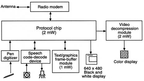
FIGURE 5-14 Functions of the multimedia terminal, including the interface to a high speed wireless link. Source: Chandrakasan and Brodersen, 1995b.
terminal electronics only have to provide the interface to I/O devices, as shown in Figure 5-15 (Chandrakasan et al., 1994). The increase in energy efficiency made possible by this system level partitioning of functions is enormous.
In the terminal design, six energy optimized special-purpose chips provide the interface between a high speed digital radio modem and a commercial speech codec, pen input circuitry, and LCD (liquid crystal display) panel displays. These chips also provide protocol conversion, synchronization, error correction, packetization, buffering, video decompression, and digital-to-analog conversion. The total power requirement for these electronic functions, when operating at a supply voltage of 1.5 V, is less than 5 mW, even while operating continuously.
The multimedia terminal project confirms that the power requirements of the Land Warrior system could be reduced by moving away from a design concept based on general-purpose computing and toward a concept based on customized embedded subsystems.
User Interfaces
The user's interface to the computer greatly affects energy consumption. The Land Warrior computer design should merge the users information space with the operational space. The system should offer seamless integration of information processing tools with the battlefield environment. To accomplish this, Land Warrior must offer natural and unobtrusive functionality, allowing the soldier to dedicate attention to the task at hand, with no distractions from the system itself. Conventional methods of interaction, including the keyboard, mouse, joystick, and monitor, all require some fixed physical relationship between user and device and are not conducive to efficient battlefield operations.
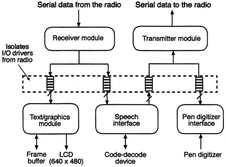
FIGURE 5-15 I/O device interfaces. Source: Chandrakasan and Brodersen, 1995b.
Human interface design is one of the most challenging problems facing Land Warrior designers. As computing devices move from the desktop to more mobile environments, many conventions of human interfacing developed primarily for office environments must be re-evaluated for effectiveness. How does the mobile system user best supply input while performing tasks that preclude the use of a keyboard? What layout of visual information most effectively describes system state or task-related data? To maximize the effectiveness of Land Warrior in mobile environments, the interface design must be carefully matched with user tasks. By constructing mental models of user actions, interface elements can be chosen and tuned to meet the software and hardware requirements of specific procedures.
The efficiency of the human-computer interface is determined by the simplicity and clarity of the mental model suggested by the system. By modeling the actual task as well as the human interface, a link can be established between user and machine that can then be examined to improve overall efficiency. The mental model of the interface design must closely parallel the model of the user task, and there must be minimal interference or obstruction by the computer to completing jobs.
Although few quantifiable metrics for evaluating interfaces are available, some basic observations can provide a means for comparison. One characteristic of an application interface is the number of user actions required to perform a given subtask. A subtask can be defined as an operation, possibly consisting of multiple inputs, that a user completes in the process of performing a larger coherent task. For example, in making an inspection, a user might wish to return
from the present location in an application to the main menu. This subtask may require a single input (perhaps a voice command or an on-screen button) or multiple inputs (backing out through a hierarchy of categories to reach the top or main level). An application that requires few inputs will allow a user to dedicate more attention to the job at hand; a larger number of inputs will require more concentration on the computing system. A comparison of equivalent subtasks in two mobile computers is shown in Table 5-4 (Smailagic and Siewiorek, 1996).
A speech recognition engine accepts complex commands and enables a series of manual inputs to be executed with a single phrase. However, the response time to a spoken input is longer, and the accuracy is lower. For these reasons, the quantitative aspect of system latency and accuracy must be considered. In evaluating computer output displays, a National Research Council report, Tactical Display for Soldiers: Human Factors Considerations, addressed the impact of information presentation on stress and workload and warned that the wrong presentation format may result in "shifting the infantry soldier's attention away from the battlefield toward a computer-generated display may compromise situation awareness and increase workload" (NRC, 1997).
Another way that the user interface can be evaluated is by its ease of use. This characteristic is difficult to quantify because it is so closely associated with human reaction, but there are at least three basic functions related to ease of use: input, output, and information representation. Table 5-5 summarizes several points for each of these basic functions. Note that, unlike the continuous variable metrics for capacity and performance, the ease of use metrics are discrete.
Like the metrics for capacity and performance in Table 5-2, the ease-of-use metrics in Table 5-5 are also moving out with time. For example, the keyboard with an alphanumeric display using textual information is representative of time-sharing systems of the early 1970s. The keyboard and mouse, graphical output, and iconic desktop are representative of personal computers of the early 1980s. The addition of handwriting recognition input, speech synthesis output,
TABLE 5-4 Comparison of the Number of Steps Required to Retrieve Information Using Selection Buttons and Speech
|
|
Buttons/Menu Selection |
Speech |
|
Get information |
4 |
1 |
|
Get photograph |
5 |
1 |
|
Navigate to location |
3 |
2 |
TABLE 5-5 Ease-of-Use Metrics
|
Input |
Information |
Output Representation |
|
Keyboard |
alphanumeric display |
textual |
|
Mouse |
graphical display |
iconic |
|
Handwriting recognition, speech recognition |
speech synthesis |
multimedia |
|
Gesturing, position sensing |
stereographic visual, audio |
3D, virtual reality |
and multimedia information emerged in the early 1990s. It takes about a decade to completely assimilate new input, output, and informational representations. By the early part of the next decade, speech recognition, position sensing, and eyetracking should be common inputs. Head-up projection displays, discussed later in this chapter, should allow superposition of information onto the user's environment.
Different interface types require different computational resources. Table 5-6 lists the approximate computer performance needed to support a given user interface when implemented in software on a general-purpose computer (Dahbura, 1996). It is clear from Table 5-6 that user interface technology influences energy consumption.
Although the size, weight, and volume of electronics will continue to shrink, mechanical interface devices have a minimum "footprint." These devices will have to be oversized for ease of use for soldiers wearing gloves or other
TABLE 5-6 Computational Requirements to Support Various User Interfaces
|
Interface Type |
Required Performance (MIPS) |
|
Textual |
1 |
|
Graphical user interface |
10 |
|
Handwriting recognition |
30 |
|
Speech recognition |
150 |
|
Natural language understanding |
1,000 |
|
Vision |
10,000 |
protective clothing. Dials and selection switches have been effectively used in such environments (Smailagic and Siewiorek, 1996). Even though there is a limit to the user interface footprint, the thickness and weight of the electronics can continue to decrease. At the limit, the "computer" could be a flexible "sheet" attached with Velcro or even woven into the outer layer of clothing.
The way that information is represented and manipulated can affect the amount of time the soldier must focus on computer tasks. During this time, the solider cannot concentrate on more urgent battlefield tasks.
DISPLAYS
This section discusses the power requirements for displays, applicable display technologies, and research and development (R&D) issues.
Requirements
The Land Warrior ensemble incorporates a helmet-mounted display in the integrated helmet assembly subsystem (IHAS), a weapon-mounted display in the integrated sight module (ISM), and a hand-held display tied to the vest.
Helmet-Mounted Display
The helmet-mounted display in the IHAS has the most stringent performance requirements of the three displays because its key functional requirement is to supply real-time imagery. Desired features include minimal energy consumption, high quality images for night operations, and situational awareness. Optimal situational awareness requires:
-
wide field of view from imager (e.g., 60 degree field of view, which requires a minimum resolution of 2,048 × 2,048 pixels for a 20 mm display [Crawford, 1996])
-
see-through viewing capability
-
peripheral vision wherever possible
In the initial Land Warrior concept, an image intensifier is planned to provide imagery on the IHAS. In the long term, however, the image intensifier will be replaced because it cannot be easily scaled up to the higher resolutions needed for a wide field of view.
Weapon-Mounted Display
The weapon-mounted displays have included cathode ray tubes (CRTs), active matrix liquid crystal displays (AMLCDs), and active matrix electroluminescent
(AMEL) displays. Peripheral vision is not as important for the weapon-mounted display, which is used in a monocular fashion for sighting targets, rangefinding, and pointing. The performance required is similar to that of the viewfinder in a commercial camcorder, except the resolution must be higher the 320×240 pixels typical of camcorders.
Hand-Held Display
The hand-held display is the most expensive of the three Land Warrior displays in terms of energy consumption. The key function of the hand-held display is to display maps, written communications, and other high resolution data. There is a basic physical limitation to the overall energy-efficiency that can be obtained by all displays designed to be radiated into 2p steradians. Only a small fraction ![]() is actually subtended by the eye of the viewer. Here a is the radius of the pupil of the eye (approximately 0.1 cm for daylight and 0.5 cm for nighttime background illumination), and R is the distance separating the center of the display screen from the center of the pupil (about 3 cm for a helmet-mounted display and 30 cm for a hand-held display screen). As a consequence, the best one can achieve is for the viewer to capture 3 percent of the radiated image energy in nighttime conditions with a helmet-mounted display. When a hand-held flat panel display is used at a 30 cm separation, the energy capture efficiency degrades to 0.03 percent.
is actually subtended by the eye of the viewer. Here a is the radius of the pupil of the eye (approximately 0.1 cm for daylight and 0.5 cm for nighttime background illumination), and R is the distance separating the center of the display screen from the center of the pupil (about 3 cm for a helmet-mounted display and 30 cm for a hand-held display screen). As a consequence, the best one can achieve is for the viewer to capture 3 percent of the radiated image energy in nighttime conditions with a helmet-mounted display. When a hand-held flat panel display is used at a 30 cm separation, the energy capture efficiency degrades to 0.03 percent.
Current and Future Technology
The principal function of a display is to convey information. Energy expended to display information that is not conveyed is wasted energy. Human factors research shows that, in optimizing situational awareness, the format of messages is just as important as the content or visual quality. In particular, studies have found that text tends to distract the viewer from awareness of the surrounding environment. Analog content, such as imagery and display symbols are not as distracting. Compared to a binocular system, the proposed monocular viewer for the IHAS is not energy efficient (NRC, 1997).
Displays will have to be in both the flat panel format for mission planning in the field and in the eyepiece configuration for the ISM and the IHAS modules. The power requirement for the flat panel displays, the more difficult of the two to reduce, can be relaxed in the near term if the duty cycle for use in the field is kept below 5 percent. The head-up display and the weapon-mounted display, on the other hand, are expected to be in use at least 50 percent of the mission duration in many scenarios. Therefore, the need to reduce energy consumption in the near term is more urgent.
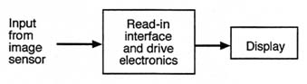
FIGURE 5-16 Block diagram of a display and associated electronics interface.
The display modules are important interfaces for the IHAS, the ISM, and the Land Warrior computer. Figure 5-16 is a generic block diagram showing the normal display configuration, consisting of a read-in interface, associated drive electronics, and the display itself.
Helmet-Mounted Display
Several trends are helping to reduce the power required by displays in portable systems. Initially, display technology was highly inefficient, especially in backlit displays, in which less than 0.5 percent of the fluorescent backlighting was used as part of the display luminescence and the rest was wasted. Through a series of refinements, the AMCLD, AMEL display, field emission display, and alternating current plasma display technologies have improved the efficiency of backlighting by almost two orders of magnitude.
Currently, the AMEL display incorporated in the helmet-mounted display on the IHAS requires that a fairly high voltage be applied across the display (65 to 200 V). Conversion losses are inevitably associated with the step up to the higher display voltage from the standard output voltage of the battery. Until recently, this would have been a major problem, but the losses associated with DC-DC power conversion can be minimized through clever circuit designs (Chandrakasan et al., 1994). Thus, the combination of AMEL display technology and high-efficiency DC-DC converters have reduced the energy consumption from 1.4 Wh to a respectable 0.32 Wh of energy dissipation in the nighttime display and 0.20 Wh in the daytime display.
Weapon-Mounted Display
Because of cost considerations, the current ISM display is a CRT requiring 1.3 W of power, 400 mW for the display, and 900 mW for the drive electronics. In investigating the conversion from a CRT technology to photolithographically produced electroluminescent displays, a redundancy was noted in having both a display and a frame buffer, when the AMEL itself can function as a frame buffer.
Therefore, some of the recent display subsystem concepts under consideration by the Army eliminate both the frame buffer and the analog-to-digital conversion step from the imaging camera, so that the analog output of the camera is read directly into the display. These two modifications would drop the power requirements from 1.3 W to 0.25 W. In the long run, AMLCD displays similar to those needed for the weapon-mounted display are being developed in the commercial arena for use as video camcorder viewfinders with typical drive powers of 0.5 W. Commercial investment in this technology is likely to drive down the cost and energy consumption of these devices.
Hand-Held Display
Hand-held displays should also benefit from developments in commercial technology, especially those aimed at the pager, cellular telephone, and electronic organizer markets. With an anticipated duty cycle of 5 percent or less, the hand-held display can readily achieve reductions in energy consumption through the addition of power management circuitry. Careful design of the interface and drive electronics should also significantly reduce the drain on the batteries. Finally, there is a move towards a cholestric liquid crystal display (ChLCD) technology, which does not require constant refreshing at a 60 Hz frame rate, only consumes energy when changing the display image, utilizes reflected light to give the optical appearance of paper, and can hold an image for months at a time using negligible power (Crawford, 1996). Although this technology is not very useful for the IHAS display or the ISM display, where full color or full motion video speed are desired, it is ideal for the display of digitally formatted data, text, maps, and other high resolution graphics. In its current form, the ChLCD is not backlit, thereby circumventing the heavy losses associated with the eye not capturing all of the display radiation. However, military requirements tend to demand both day and night capability, so some form of lighting must be conveniently available to illuminate the display. Recent advances in the use of electroluminescent light (such as the illumination in INDIGLO™ watches) may have to be incorporated into the ChLCD display.
Future Research and Development
The state of the art in the read-in interface can clearly be improved through the introduction of carefully designed ultra-low power electronics (ULPE) and power management techniques. However, physical limitations will restrict how much the energy consumption in flat panel displays can be reduced, especially the backlit architecture.
TABLE 5-7 Radiated Energy Captured by the Viewer
|
Display Type |
Daytime (worst case) 0.1 cm Diameter Pupil (%) |
Nighttime (best case) 0.5 cm Diameter Pupil (%) |
|
Helmet-mounted display |
0.1 |
3 |
|
Hand-held display |
0.001 |
0.03 |
|
Virtual retinal display |
~100 |
~100 |
Because ''see-through" displays improve situational awareness, the virtual retinal display is a highly energy-efficient, long-term candidate for insertion in the Land Warrior system (Inside the Army, 1996). The high efficiency is due to the fact that nearly 100 percent of the light emitted by the display is captured by the eye, unlike flat panel displays, which by design emanate into 2p steradians so that they can be viewed from any angle. In addition, proper design of the mechanical mounting fixture can minimize obstruction of the field of view. Because the laser diodes can be operated at the standard CMOS operating voltages, and the operating currents can be designed to work at tens or hundreds of µA, the power required to operate the lasers is very low, less than 500 µW.
In fact, one would expect the power requirements for a virtual retinal display to be dominated by its drive electronics and the scanning mechanism. The former could be minimized through the application of standard ULPE design and power management techniques, and the latter could be accomplished either by acousto-optic deflection of the optical output or by using microelectromechanical parts, whichever proves to be more reliable and efficient. Table 5-7 summarizes the anticipated energy capture efficiency by the viewer using each of the three display technologies.
In summary, three development trends are helping to bring down the energy consumption characteristics associated with displays:
-
improvements in backlighting efficiencies
-
improvements in DC-DC voltage converter efficiencies
-
system-level redesigns of the display subassembly to achieve optimal energy conservation within the context of the function
Future technology requirements unique to the Army include low power, high-pixel-density, video-quality displays to support improved situational awareness with wide field of view on the helmet-mounted display and with resolution sufficient for positive target identification on the weapons sight. Commercial technology trends should support Army requirements for higher resolution and lower refresh rate on hand-held displays. However, the 320 × 240 resolution typical of commercial imagers will not be adequate for the Army's
target recognition requirements. Consequently, even though commercial investment in this technology is likely to drive down the cost and energy consumption of these devices, the military will still have to invest to achieve higher resolution.
SENSORS
The combined purpose of the sensor suite is to improve the situational awareness of each soldier to enhance his or her lethality and survivability. In addition, Land Warrior will extend the command and control capability by supporting real-time target location and call-for-fire and by supplying sensor information up the chain of command to improve decision making. For example, data from signals intelligence, chemical detectors, and laser sensors may paint a more accurate picture of a threat as it develops. The sensor suite deployed with the dismounted soldier must also be optimized in design and performance to minimize the drain on energy resources thereby extending battery life and reducing the number of backup batteries required to complete a mission.
A range of sensors is thought to be useful for deployment in support of the dismounted soldier. Currently, many of these modules require excessive amounts of power, as can be seen in Table 5-8. One of the by-products of the campaign to
TABLE 5-8 Land Warrior Sensor Suite Power Requirements
|
Function |
Cumulative Peak Power (W) |
Function Operating Power (W) |
Standby (Alert) Power (W) |
Operating Duty Cycle (%) |
Average Operating Power (W) |
Projected (2015) Goals for Average Operating Power (W) |
Projected (2015) Two-Week Mission Goals for Energy Use (Wh) |
|
GPS |
1.80 |
1.50 |
0.60 |
45 |
1.00 |
0.168 |
|
|
Video camera |
1.20 |
1.00 |
0.00 |
15 |
0.20 |
1.340 |
|
|
ISMd |
7.80 |
6.00 |
0.00 |
Table 5-9 |
2.80 |
0.094 |
15.800 |
|
IHASe |
5.80 (night) |
5.60 (day) |
0.25 |
Table 5-10 |
2.80 |
0.075f |
4.200f |
|
a Numbers obtained from Stanford models on GPS design; assumes 5 percent duty cycle b Power required before accounting for duty cycle c Assumes color and high resolution upgrades d See Table 5-9 e See Table 5-10 f Assumes development of virtual retinal (VRD) color display Source: Efkeman, 1996. |
|||||||
minimize the power requirements of these sensors and other electronic aids is a reduction of the soldier's electronic signature, which will improve survivability. Other by-products are a reduction in battery weight and lighter, more compact sensors. This is important because every pound saved in battery weight or in the accompanying sensor suite translates directly into ammunition or food the soldier can carry.
Only the sensors appropriate for a particular mission should be carried. This will require a modular system, one that would also facilitate later upgrades of sensor technologies. As the technology advances, one is likely to be able to improve energy efficiency by including different sensors within an integrated assembly, as has been done with the IHAS and the ISM.
Table 5-8 lists power requirements for the current Land Warrior suite of sensors. Detailed breakdowns for the integrated IHAS and ISM are shown in Tables 5-9 and 5-10. Except where noted, the projections of future performance for these electronics assume that current power levels are obtained by using 5V commercial CMOS technology and standardizing to a common voltage wherever possible. Note that improvements projected for the IHAS in Figure 5-10 are achieved by scaling to decreasing drive voltages. This implies a need to be alert for and to develop technologies that are voltage-compatible with commercial CMOS whenever possible.
Additional reductions in energy consumption are possible by introducing power optimizing hardware and software design methodologies. However, it should be emphasized that these design trade-offs should be made in the context of a top-down evaluation of the overall system. Although the tables and the discussion in this chapter focus on ways to minimize energy consumption in the
TABLE 5-9 Integrated Sight Module (ISM) Power Requirements
|
Function |
Function Operating Power (W) |
Operating Duty Cycle (%) |
Average Operating Power (W) |
|
Controller |
1.265 |
50 |
0.633 |
|
Direct view optic (DVO) |
0.075 |
10 |
0.008 |
|
IR sensor processor |
2.425 |
50 |
1.213 |
|
Thermoelectric cooler (TEC) |
0.100a |
50 |
0.050 |
|
Display |
1.300 |
50 |
0.650 |
|
Regulator |
0.360 |
50 |
0.180 |
|
Compass |
0.350 |
10 |
0.035 |
|
Laser rangefinder |
~0.05 |
10 |
0.005 |
|
IR pointer |
0.075 |
10 |
0.008 |
|
TOTAL |
6.00 |
— |
2.78 |
|
a Assumes operating temperature extremes of -32°C to +49°C. Source: Marshall, 1996. |
|||
TABLE 5-10 Integrated Helmet Assembly Subsystem (IHAS) Power Requirements
|
Function |
Function Operating Power (W) |
Operating Duty Cycle (%) |
Average Operating Power (W) |
|
Day display |
0.200a |
50 |
0.100 |
|
Night display |
0.320a |
50 |
0.160 |
|
Display electronics module |
|||
|
Video board (including AC power converter) |
4.000 |
50 |
2.000 |
|
Miscellaneous electronics board |
0.120 |
50 |
0.060 |
|
DC power conversion module |
0.610 |
50 |
0.305 |
|
Laser detector |
0.600 |
50 |
0.300 |
|
Imager |
0.100 |
50 |
0.050 |
|
Total |
|||
|
Day |
5.63 |
— |
2.82 |
|
Night |
5.75 |
— |
2.88 |
|
a Assumes AMEL display. Source: Doney, 1996. |
|||
individual subassemblies deployed with Land Warrior, effective optimization of the system must involve a top-down evaluation.
In general, one can predict the drop in power requirements (assuming everything else remains fixed) by scaling the drive voltage. The ISM, IHAS subsystem, and the GPS module incorporate analog technologies that do not scale with the square of the voltage and are exceptions to this scaling rule. Other ways to reduce power are discussed in the following sections.
Because all of the functional requirements have not been defined for the laser detector, a conservative estimate of its initial power requirement was assumed to be one-tenth that of a full imaging array. In fact, this number will probably be much lower because the laser detector should not require an analog-to-digital converter.
Microelectromechanical Systems
Microelectromechanical systems (MEMS) are used in photolithographic technology for the fabrication of high-aspect-ratio (100:1) microscopic structures. MEMS technology may also apply to the micromechanical turboalternators discussed in Chapter 3. The addition of MEMS structures in the sensor modules
would enhance functionality, lower cost by achieving economies of scale, and reduce energy consumption. In particular, the fabrication of microbolometers with MEMS technology is expected to improve the image resolution of infrared sensor arrays by eliminating cross talk among the adjacent sensor pixels.
MEMS could also be used to implement sensor mechanisms with moving parts, such as microshutters; microchoppers for the infrared sensors; chemical sensors, such as miniature mass spectrometers ("electronic noses"); and micromechanical beam writing scanners for the virtual retinal display. MEMS technology may also apply to micro-machined oscillators, filters, diplexers, and switches used in radio communications.
Currently, there is no MEMS technology road map like the NTRS (discussed in Chapter 4). However, the list of potential mass market commercial applications for MEMS is growing rapidly. By the year 2,000, it is estimated that the MEMS worldwide market will be nearly $14 billion and will enable almost $100 billion in new or improved systems (SPC, 1994). The biggest markets will be in the automotive and medical fields. This compares with a projected market for high-definition television (HDTV) of $7.1 billion in the year 2000. Thus, it is very likely that by 2001, the MEMS application base will have grown large enough to warrant an industry road map. This will significantly lower the cost for many of the MEMS technologies the Army will need.
Infrared Sensor Arrays
Several infrared wavelength bands are important to military imaging applications. They have different strengths for imaging in terms of sensing the surrounding environment. The bands are 1 to 2 µm; 3 to 5 µm; and 8 to 12 µm.
The 1 to 2 µm band is used for laser detectors to sense and warn soldiers when lasers or other infrared targeting optics are being used. The other two bands are more likely to be used in imaging applications because they can provide imaging capability for both day and night missions. However, many complex issues must be considered in selecting one or the other, including the fact that the 8 to 12 µm band detects a higher radiance from the scene, while the 3 to 5 µm band offers higher contrast. Some of these sensors require cooling or temperature control; others are uncooled but still require ±0.05°C temperature stabilization at the operating temperature to ensure noise equivalent temperature differential (NETD) values of 0.1°C.
Figure 5-17 is a block diagram of a generic imaging array and associated electronics. In both the cooled and uncooled sensors, very little energy is consumed by the imaging detector array itself. Traditionally, the temperature controller circuitry, the readout interface, drive electronics, and analog-to-digital converters dissipate most of the energy. In addition, the earliest version of the cooled sensors required a significant amount of power to maintain cryogenic temperatures.
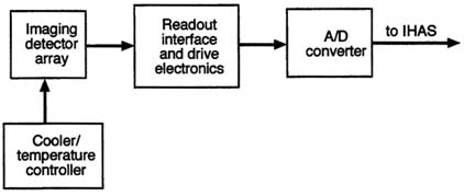
FIGURE 5-17 Block diagram of a generic imaging array.
Temperature Stabilization
The physical limits of minimizing power requirements with cooling technology is driven by the temperature differential that must be maintained between the ambient environmental temperature and the sensor's operating temperature, according to the expression:
where q is the heat to be dissipated at the cold face of the thermoelectric cooler, κ is the thermal conductivity, A is the area, dt is the temperature difference between the hot face of the TEC and the cold face of the TEC, and dx is the thickness of the heat sink (i.e., the TEC thickness). Although both heating and cooling capabilities are required by military specification to stabilize a sensor over a given temperature range, this discussion will focus on cooling because it is less efficient than heating.
Optimal cooling efficiencies are obtained when TEC modules are run at a small percent of their operating maximum and when the thermal temperature differences across the cold and hot faces of the module are small. This is accomplished by:
-
lowering the heat load of the electronics by reducing energy dissipation
-
keeping the difference between the temperature of the sensor head and the ambient temperature small
By overdesigning so that the TEC cooling capacity is a small fraction of the heat loads, cooling efficiencies of 75 percent or better are achievable (MacLannon, 1997). This realization led to a significant shift away from cryogenically cooled detector arrays to temperature controlled bolometers that operate near room temperature. This means that sensor cooling power will only be
required to maintain control over small temperature shifts from room temperature (5°C≤Δ≤10°C offset from the ambient temperature) instead of the 223°C temperature differential required for cryogenically cooled systems. The power requirement is expected to be reduced from the 1,000 mW peak value associated with temperature extremes in the MILSPEC range for cryogenically-cooled systems to the nominal 100 mW of power indicated in Table 5-9.
Two candidates are under extensive development by the Army (Flannery and Miller, 1992):
-
capacitive bolometers made of barium strontium titanate (BST) in the 3 to 5 µm band
-
resistive bolometers made of vanadium oxide in the 8 to 12 µm band
The resistive bolometer sensors employ a bridge technology that thermally isolates the resistive film on a thin mechanical bridge so that large NETDs can be sensed for thermal differentials as small as 0.1°C. The capacitive or ferroelectric bolometer technology operates on a similar principle, except that it is continuously chopped (resistive bolometers need to be periodically shuttered every 15 minutes or so to recalibrate the system). Capacitive bolometers are also moving towards microbridge technology in an effort to minimize cross talk caused by thermal diffusion among adjacent pixels; this would reduce the extent to which the image resolution is limited by optical components.
Future Research and Development
The fundamental technology common to both resistive and capacitive bolometers is the MEMS high-aspect-ratio fabrication technology. Currently, process yields in MEMS are not very high, yet high yields are vital to keeping costs of high-density imaging arrays down. The Army will have to give a high priority to supporting the development of these sensor arrays, at least until MEMS acquire a large enough commercial base to justify the definition of a MEMS technology road map. Coupling this progress with improvements in thin-film deposition may pave the way for long-wavelength detector arrays that do not require active temperature stabilization to a fixed temperature but can be stabilized against an ambient background. If the fabrication problems can be solved, thermocouple junction thin films have the added advantage of generating an internal voltage, which eliminates the need for an external power source.
Ultra Low-Power Electronics for the Sensor Interface
The active pixel sensor (APS) is a second-generation, monolithic sensor with one or more active transistors per pixel, which enables development of low-power, low cost, highly miniaturized instruments for use in space missions.
Unlike the widely used charge coupled device (CCD) imagers, APS sensors do not require repetitive charge transfers and therefore do not require special fabrication technology. APS, as developed at the Jet Propulsion Laboratory (of the National Aeronautics and Space Administration), is fabricated by commercially available CMOS technology, enabling implementation of highly integrated "camera-on-a-chip" imaging systems (Dickinson et al., 1995; Nixon et al., 1996) Unlike CCD, a CMOS APS is a random access, low capacitance device. Furthermore, use of CMOS technology allows integration of on-chip timing and controls with the APS. The resultant imager system-on-a-chip exhibits ultra-low power requirements (more than a 100-fold reduction compared to the state of the art) and extensive miniaturization (more than tenfold reductions in mass and size). Integration of on-chip electronics for camera timing and control, signal conditioning and noise shaping, analog-to-digital conversion, and interface definition leads to imaging systems with extremely high performance (low noise, high functionality, high speed, high reliability, and ultra-low power requirements.)
A CMOS APS operates from a single 5 V (or 3.3 V) supply and features large format (1024×1024), high resolution (< 12 µm pitch), wide dynamic range (more than 75 dB), digital I/O, random access readout, low smear, antiblooming control, and electronic shuttering, with excellent imaging performance (quantum efficiency similar to interline CCD, and noise < 12 e- r.m.s.). It enables visible imaging in many different formats. The total system power requirement is far lower than the requirement of the analog-to-digital converter alone in a conventional imaging system because there is no need to drive the analog signal off the chip before the converter.
Because APS arrays are completely silicon-based, including the detectors, they respond in the visible and near-infrared (0.4 µm to 1.0 µm) wavelengths and fall outside the wavelength bands of key interest to the Army. Nevertheless, the lessons of this commercial technology have led to lower power consumption and lower costs in interface electronics, which can be translated to improvements in similar interfaces on infrared detector arrays. The challenge will be to find ways to achieve single-chip integration of the detector materials that can sense the longer wavelength radiation bands (3 µm to 5 µm; and 8 µm to 12 µm) by developing thin-film deposition techniques for both BST and vanadium oxide, the materials used for uncooled detectors.
Indeed, a long wavelength vanadium oxide microbolometer focal plane array based on commercial CMOS technology is available for both commercial and military use (Butler et al., 1996). The developers have integrated onto a single focal plane array features such as nonuniformity correction, auto gain and level correction, television video, and analog-to-digital converter output. The array is a 327×245 pixel array with a 10-bit analog-to-digital converter at a 6.1 MHz output data rate and a 60 Hz frame rate. It requires less than 500 mW of power, 250 mW of which is attributed to the analog-to-digital converter. Much of the energy savings in this display comes from standardizing to 5 V with commercial
CMOS and using an on-chip analog-to-digital converter. These numbers will improve with the push towards lower chip voltages.
Research and Development
Future R&D should focus on further reducing dependence on the TEC. In addition to ongoing work to improve the yield of capacitive and resistive bolometers, thermocouple bolometers for reducing the thermal offset energy consumption at the TEC should be investigated. Once MEMS fabrication techniques have advanced, microbolometer structures could be integrated onto chips with CMOS circuits without degrading CMOS performance. Ultimately, merging MEMS and CMOS should bring down the cost of these sensor systems. A commercial industry guideline similar to the NTRS should improve technology development.
Laser Detectors
Currently, a single laser detector mounted in a frontal position on the helmet is used for Land Warrior. This positioning does not optimize situational awareness because when lasers come into play on the battlefield, they will be used largely as a means of acquiring targets, whether tanks, trucks, or foot soldiers. Laser detection would be enhanced with sensor coverage in all four directions of the helmet and a sensor net on the soldier's vest. This would improve the soldier's chances of being forewarned when he or she has been targeted. Cloaking the soldier in a large number of surface-mounted detectors at various points on the vest and helmet, however, would be costly in terms of energy; the duty cycle for the laser detector will probably be 50 percent or more over the course of a mission. Furthermore, it is difficult to make sensors rugged enough to prevent damage in the combat environment.
One way to solve this problem would be to weave 100 or more lensed light collectors in the form of multimode fibers into the vest and helmet. By fusing the output ends of the fibers, their integrated output could be used to illuminate a common detector. Two common detectors, one located in the helmet and one in the vest, are illustrated in Figure 5-18. The embedded collectors could capture laser radiation from different locations and directions and feed it to a combination detector-amplifier. A network of optical collectors might also double as the backbone for an infrared wireless link between the helmet, vest, and weapon to handle data. Power requirements for the wireless communications interfaces needed to link the soldier subsystems are discussed in a later section in this chapter.
The heart of the laser detector technology is similar to the technology of infrared imaging arrays, i.e., a single detector with an adjacent preamplifier and ASIC (application-specific integrated circuit). One might locate three or four
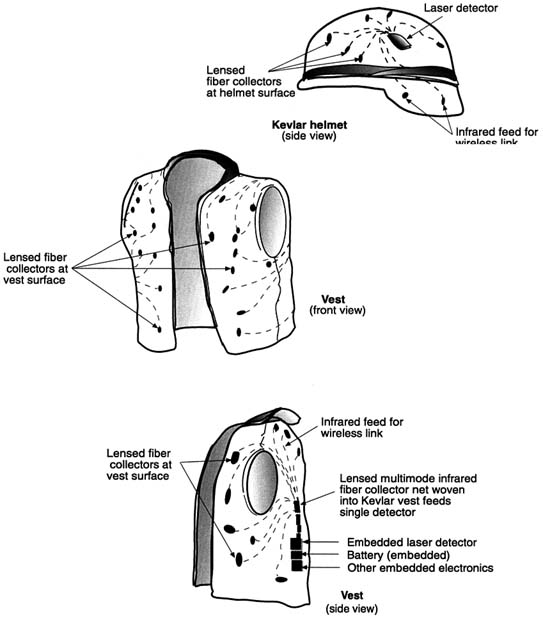
FIGURE 5-18 Soldier's vest and helmet with laser detectors.
detector-amplifier combinations on the same chip, each fed from a fiber bundle that recovers signals from a different direction (enabling the user to distinguish the general direction of the source). Other functions might be included on the chip to permit the user to measure wavelength and other signature information, such as pulse length. If the large infrared sensor arrays and their associated control and analog-to-digital converter electronics can be deployed requiring 50 mW of power using 5 V CMOS technology, the same technology applied to a single system would enable power requirements of less than 5 mW.
Research and Development
Weaving multimode fibers to serve as light collectors into the soldier's Kevlar vest and helmet material will require supporting technology development.
Laser Rangefinders and Infrared Pointer Technology
The minimum average optical output of the laser rangefinder is 1 mJ. This level is currently achieved with a diode-pumped solid state neodymium: yttrium lithium fluoride (Nd:YLF) laser with difference frequency shifted to an eye-safe wavelength of 1.5 mm. The rangefinder has a nominal operating power of 50 mW and peak power requirements of 750 mW in the Q-switching mode. Because the range to a target can usually be established with a single pulse, the duty cycle during peak power mode of operation is expected to be very low (< 3 × 10⁻⁵ percent). Consequently, energy consumption is dominated by the nominal operating condition. For the 50 mW quoted, the 5 percent duty cycle implies that the average power requirement over a 12-hour mission will be 2.5 mW.
In contrast, the infrared pointer is a light emitting diode operated in continuous-wave mode and has an output power of 1 mW. Its peak power requirement is 75 mW, and its 5 percent duty cycle implies that the average power required over a mission will be about 4 mW.
Laser Rangefinder
With diode lasers, it is possible to achieve 65 percent power conversion efficiencies from edge-emitting lasers, although 25 percent is typical of commercial lasers. Under the best of circumstances, one might also obtain 80 percent power conversion efficiencies in pumping the Nd:YLF laser with the diode laser and another 71 percent when converting from 1.06 µm to 1.5 µm. Naturally, the actual wavelength conversion efficiencies are considerably worse than this, so that most of the power requirement in the laser rangefinder is accounted for by converting the optical energy to the 1.5 µm wavelength. This rather complicated process for obtaining the 1.5 µm was used in the early stages of the Land Warrior because there were no direct diode sources of 1.5 µm that could supply energy pulses as large as 1 mJ. However, if the current trends in diode laser technology development continue, a 1.5 µm wavelength diode laser could be switched to achieve the 1 mJ per pulse requirement. Because p-n diode technology is one of the most efficient means of converting from electrical to optical energy, a direct diode replacement for the current arrangement would optimize the design in terms of power consumption. Given the current trends, an adequate R&D strategy would be to track this particular technology and convert to a direct diode laser source when it becomes available.
Infrared Pointer
For the infrared pointer, although the power requirement is dominated by the electrical-to-optical conversion efficiency, 10 mW of the total 75 mW of operating power is nonetheless attributable to the electronics interface with the computer. By using ultra-low power design strategies, the power required at this interface can be reduced below 1 mW. With respect to the electrical-to-optical conversion, the typical power conversion efficiencies of light emitting diodes (LED) are similar to diode lasers, but because of the radiation pattern, only a small percentage of the emitted light is subtended by the collection optics (6 percent with an optimized design for the collection optics). Thus, the optical conversion efficiency could be further improved by replacing the diode laser with an LED, which would reduce the power required to generate 1 mW of infrared radiation to approximately 4 mW and would result in a net total drive power of 5 mW for the infrared pointer.
Cost has been the major reason for selecting an LED over a laser diode in many applications, but costs are expected to fall as multimedia communications using high bandwidth fiber optics reach the mass consumer market.
Research and Development
High optical losses in the current prototypes will be offset to some degree by expected low duty cycles. Low average power requirements make R&D to reduce energy loss in the infrared pointers a low priority compared to losses due to other sensors. The optical conversion efficiencies are expected to continue to rise as a result of heavy investment in R&D by telecommunications companies and other companies concerned with users of multimedia and the internet. Commercial R&D will focus heavily on lowering the cost of the optical subcomponents. The Army stands to benefit from this commercial investment, although commercial interests will not be concerned with packaging these devices compactly to withstand the rugged environment of military operations.
Global Positioning System
The most common use of the GPS (global positioning system) by the dismounted soldier is for land navigation. GPS is also used in search and rescue operations, and there are plans to adopt it for precision delivery of cargo by parachute or paraglider. A major concern to the Army is the potential for primary interference from deliberate jamming or spoofing by an adversary or by friendly forces. Therefore, all GPS-based navigation systems must have one of the following features: sufficient jamming-to-signal ratio strength to navigate through the jamming environment; the ability to null out the jamming signal; or an alternative to GPS for navigating through the jamming environment. Full GPS
accuracy would thus be denied to the enemy by selective availability and by antispoofing security procedures. The GPS receiver in the soldier's sensor suite must be capable of meeting all of these requirements.
The GPS receiver in the Land Warrior ensemble has two power management modes, continuous mode and fixed mode. In the continuous mode, the receiver is in continuous operation, and the battery is good for about 10 hours. In fixed mode, the unit is powered on once every 15 minutes, increasing the battery life to about 40 hours. Another power management option would be to activate the GPS only on demand because the average mobility of a foot soldier does not require continuous updates. The Army is also investing in a longer term program to develop an ULPE GPS module. Currently, GPS research is focused on three topics: integrated CMOS technology; low voltage front-end receiver circuits; and fast synchronization and reacquisition algorithms.
The operation of a GPS receiver involves three data acquisition phases: acquisition of the almanac information; acquisition of the ephemera information; and acquisition of phase synchronization. The almanac data takes at least 12.5 minutes to acquire and must be updated every few days. Ephemera information takes about one minute to acquire and must be updated about every four hours. Even though these two kinds of data take a long time to acquire—the low data rate of 50 bits per second still results in a duty cycle of less than one percent—the impact on energy consumption is not as important as the problem of phase synchronization. Therefore, attempts to reduce the power requirement for GPS have been focused on reducing the active power and the time required in phase synchronization (Meng, 1997).
To reduce the active power of a GPS receiver, the design of both analog and digital circuits must be optimized for low power. With recent developments in CMOS technology, highly integrated circuits can operate in the GHz range, which provides a low cost, low power solution to the problem. Based on a 0.35 µm CMOS design, a combined low noise amplifier and mixer operating at 1.6 GHz requires less than 7.5 mW with reasonable gain of 20 dB and less than 3 dB of noise figure (Shahani et al., 1997). The GPS front-end circuits can be implemented in less than 10 mW, using standard CMOS technology (Meng, 1997).
After the GPS signal has been converted to a low intermediate frequency on the order of a few megahertz (MHz) in the receiver, an analog-to-digital converter can be used to digitize the analog data to binary bits. A 2-bit converter operating at 20 Mhz requires less than 1 mW of power, which does not impose a power concern on the overall design (Meng, 1997).
A composite correlator architecture has been developed for GPS data acquisition to implement multiple-channel demodulation without incurring much overhead in power. As a result, the GPS receiver can perform 6-channel or 12-channel acquisition at a fairly low clock rate without the usual power penalty. The active power for data acquisition is estimated to be around 10 mW, assuming continuous operation (Meng, 1997).
The base-band signal processing for the calculation of positions and timing will employ dedicated low power digital circuits operating at 1 V supply voltage. Using dedicated hardware, flexibility is traded off for a reduction in power. Simulation shows that the power required for calculating positions and timing is negligible (less than 1 mW) because updated information is only needed once every few seconds (Meng, 1997).
Current GPS systems take at least 1 second to reacquire phase synchronization, to demodulate the received signal accurately, and to estimate the pseudo-range. Instead of using the standard early-delay loop for this purpose, a phase-error interpolation scheme was developed that requires only a fraction of a second for accurate phase synchronization. By employing this new phase-lock algorithm, the overall average power, or the duty cycle, is reduced. For example, to monitor a position continuously, the GPS may have to be turned on every 2 seconds without losing bit synchronization. If it takes only 100 milliseconds, instead of 1 second, for phase synchronization, the total energy dissipation will be reduced by a factor of 10, regardless of the actual active power (Meng, 1997).
A single-chip GPS receiver fabricated in the standard 0.35 CMOS technology that requires less than 20 mW of active power is now feasible. When factoring in the duty cycle, a GPS receiver estimating a position every 2 seconds will require an average power of 1 mW, which allows a much longer battery life than any of the current designs (Meng, 1997). Table 5-11 shows the Army's progress in reducing the power requirement of GPS receivers.
Research and Development
According to projections by Booz-Allen Hamilton, Inc., there are five major commercial arenas that can be expected to drive the GPS technology base between 1994 and 2003 (NRC, 1995):
-
land vehicles (223 million units fielded)
-
marine vessels (21 million units fielded)
-
aircraft (312,000 units fielded)
-
surveying/mapping (690,000 units fielded)
-
personal use
GPS market forces are dominated by land vehicles, marine vessels, surveying and mapping, and aircraft. Personal use, including self-surveys, golfing, emergency location, fishing, sailing, and hiking, is expected to be negligible. However, products for personal use are expected to have the same low power consumption and portability characteristics that are needed for the military. The only other commercial market that might potentially need low power would be surveying and mapping. Neither market is large enough to stimulate a major commercial technology push toward Army goals; therefore, low power GPS for
TABLE 5-11 GPS Power Requirements
|
Nomenclature |
Year |
Battery |
Power (W) |
|
AN/PSN-8 |
1985 |
BA 5590/U |
46.5 |
|
AN/PSN-9 |
1987 |
BA 6598/U |
9.8 |
|
AN/PSN-10 |
1988 |
BA 5800/U 2 each BA 3058/U 8 each |
5.0 |
|
AN/PSN-11 |
1993 |
BA 5800/U 2 each BA 3058/U 8 each |
5.0 |
|
Land Warrior |
2000 |
— |
1.5 |
the dismounted soldier and other military applications will require R&D investment by the Army.
Wireless Communication Interfaces
Communications among the weapon, vest, and helmet in the objective Land Warrior system will be accomplished with two RS-232 cable data links connecting the vest computer with the ISM. The ISM can support two displays. One is an actual display in the eyepiece on the ISM located on the weapon. The other is a video output, RS170/RS422, from the ISM either to the vest computer or directly to a display in the IHAS. Normally the ISM feeds the computer, which feeds the IHAS.
Replacing the cables with a wireless interface would have advantages of lower weight and more flexibility. Adopting a wireless interface, however, means using separate batteries for each of the three sensor suite subsystems in the vest, the weapon, and the helmet. Of the three subsystems, the helmet will require the smallest, lightest battery in order to minimize torque on the head from the weight of sensor electronics. This also means that the size and shape of the electronics package must be ergonomically sound. The vest-mounted electronics, because they hang directly from the torso close to the body's center of gravity, have the fewest restrictions on size and weight.
Current and Future Technology
There are two possible approaches to using wireless connectors. One is to rely on radio frequency transmission between the three separate subsystems. The other is to develop infrared frequency transmission (using either LEDs or diode lasers) that use fiber collector nets to complete the link through a variety of different orientations of the subsystems with respect to each other. The latter
approach could take advantage of the light collection technology developed to enhance the laser detector (described earlier).
Radio Frequency Wireless Interface The Land Warrior system uses an RS-232 bus for a hard-wire interface. In the RS-232 protocols, all nodes are in a continuous listen/transmit mode, whether data is being transmitted or not. An alternative, more energy-efficient protocol would help to reduce the load on the battery. For example, a DARPA supported program for a wireless interface called a BodyLAN (local area network) uses a time division multiple access (TDMA) protocol at a 900 MHz carrier frequency to reduce power. Other features of the BodyLAN are as follows:
-
wireless nodes that can be clipped anywhere on the body
-
reliable network range of 1.5 meter, i.e., limited to the immediate proximity of the body
-
TDMA timing structure with nodes powered on to receive control information and/or data
-
nodes that are provided regular transmission opportunities by the controlling hub and otherwise power-down the transmitters
-
varying levels of communications reliability layered on top of the basic structure, ranging from unchecked datagrams to a highly reliable forward-error-correction scheme coupled with packet retries
The anticipated performance characteristics of a BodyLAN system following this set of protocol rules are shown in Table 5-12.
Optical Wireless Interface Once optical wireless links are available at comparable energy consumption levels to those achievable with BodyLAN, one can begin to trade off the advantages of optical and radio frequency links. The chief reason for considering optical interfaces is that they are intrinsically wideband and can thus easily accommodate a more complex sensor suite. Optical links are also highly resistant to jamming.
Trade-offs between low signature, reliability, ease of maintenance, and other criteria, will have to be carefully considered when weighing the merits of designs employing these two wireless technologies, but it will not be necessary to choose one or the other. Optimal performance can probably be achieved by including both a radio frequency and an optical wireless link in the sensor suite. This dual-string design would permit operation in either a normal mode or a clandestine antijam mode, as needed.
The power requirement for a wireless configuration will never be as good as what can be achieved with a well designed hard-wire link. Still, a wireless link should be more reliable because hard-wire connector joints are subject to severe stress in the field.
TABLE 5-12 Performance Characteristics of the BodyLAN
|
Specification |
Near Term |
Future |
|
Size |
= 1.6 in3 |
= 0.56 in3 |
|
Weight |
= 15 g |
= 5 g |
|
Aggregate raw data rate |
70 kbps |
70 kbps |
|
Power required (full rate) |
7.6 mW |
5 mW |
|
Power required (sleep) |
1.3 mW |
0.03 mW |
|
Peak transmit power |
375 µm |
375 µm |
|
Number of nodes |
128 |
128 |
FINDINGS
Advancing microelectronics technologies hold great promise for reducing the power requirements of systems for the dismounted soldier. Processing capability and device complexity are growing according to Moore's law, i.e., doubling every 18 months. Processor clock frequency has also risen at a rate of about a factor of ten every nine years. These improvements have brought into focus the importance of energy considerations, especially for portable devices. The performance of portable devices is subject to the limitations of battery technology, which is improving comparatively slowly, despite many years of generous spending on R&D. Both the Army and commercial industry are seeking more energy-efficient systems. Fortunately, they are achievable in most of the relevant technologies.
Communications
The energy efficiency of radio frequency wireless transmission is not likely to improve substantially in the future. However, network architectures and communications protocols can be optimized for energy efficiency. Careful attention to circuit design and operation, system architecture, and system integration have reduced the power requirements of some specialized commercial microprocessors (such as those in cellular telephones) by about an order of magnitude in the past few years. Continued improvement can be expected.
The energy needed to support transmission of high speed data will increase in relation to other Land Warrior energy demands. A tenet of communications systems for the dismounted soldier should be to deploy the computational components of the system in a manner that minimizes wireless communication. In general, computational components should be placed so that data collection and reduction are performed as close as possible to the site of the data collector.
Computing
The Land Warrior computer, basically a general-purpose laptop PC, is connected to all subsystems and is expected to consume about 180 Wh for a 12-hour mission. This demand could be reduced by 50 to 80 percent through system-level power management techniques using general-purpose components and energy-efficient software (compilers that explicitly consider energy per operation). Replacing the general-purpose computer with distributed dedicated processors optimized for low energy consumption could yield reductions of two orders of magnitude. Critical chips within a multimedia terminal combining both computing and radio functions have already been designed to draw 5 mW—three orders of magnitude less than existing commercial counterparts.
Displays and Sensors
Improvements in the drive electronics for both displays and imaging sensors will account for most of the reductions in power requirements for the sensors, the ISM, the IHAS, and the hand-held displays. Digital control electronics of the sensors can be expected to follow the same trends as other computing devices through the use of lower voltage CMOS technology. The exceptions that will not benefit from this steep falloff are the analog subassemblies in the sensor system (i.e., displays, temperature controllers, pulsed lasers, infrared pointers, etc.). R&D already under way can be expected to reduce the power requirements of the combined display and sensor suite to less than 390 mW, more than an order of magnitude better than estimates in the Land Warrior system design.


