
1
Introduction
Automatic identification systems (AIS) technology has been under development for well over a decade and has had at least two major driving forces behind it. First, mariners are interested in effective, reliable, and automatic vessel identification for a number of practical reasons:
-
To eliminate the need to blindly call a vessel on VHF with a message seeking to identify another vessel (e.g., “northbound ship on my port bow”),
-
To eliminate or reduce the hazard of making collision avoidance arrangements with the wrong vessel, and
-
To identify a rogue ship holding on in contravention of the rules of the road.
Second, governmental agencies of coastal states that are responsible for the prevention of and response to marine pollution incidents, conservation of natural resources, vessel traffic management, maritime security, and law enforcement are interested in vessel identification as well as in monitoring certain vessel activities and movements. Until AIS and similar technologies came into use, such monitoring required physical sighting and identification of the vessels of concern, voluntary reporting by such vessels, or, in the proximity of a coast, use of radar or other active surveillance. All of these methods have significant drawbacks, not the least of which is cost.1
In addition to these two principal driving forces, commercial interests have motivated AIS development. Commercial interests include port authorities, vessel operators, and pilots, all of whom seek to improve safety and facilitate commerce through improvements in the availability and timeliness of the information available to mariners. AIS can contribute to such improvements unobtrusively without reliance on voice communications. Of these
forces, however, governments for the most part have led in shaping the technology and its applications.
The mariners’ requirement for vessel identification could have been met by shipboard installation of transponders similar to those in common use in aircraft. When triggered by the receipt of radar impulses, such transponders respond in a manner that “paints” the name and call sign of the carrying ship next to the target as shown on the querying radar. However, there are limits to the amount of information that can be provided by such transponders—positional information provided by such transponders is relative to that of the querying ship, and its accuracy is determined by the radar used. Therefore, early marine transponder developments (i.e., before 1990) led to a second type of transponder system termed automatic dependent surveillance (ADS), which consists of a radionavigation receiver utilizing systems such as the Global Positioning System (GPS), Differential GPS (DGPS), or Loran-C coupled to a communications device capable of transmitting position and other predetermined information to a suitably equipped receiver. The advantages of this approach over a radar-based system, which is used in aircraft, include greater positional accuracy, longer ranges (depending on the communications medium used), and an ability to transmit a greater volume of data.2
Over the last 10 years transponder-based systems have been used in a variety of applications. For example, one system is used to identify fishing vessels as a tool in fisheries management (Zamora 1999). In the United States, other applications include a vessel traffic management system developed for the Tampa Bay waterways (see Chapter 3), ferry systems that use it to monitor ferry movements, and rescue tugs that are coordinated for marine emergency response in Puget Sound using AIS.
Standardization of these AIS developments is critical because shipping is an international business and it is essential that mariners find the same information environment wherever they sail. Over the past few years, the International Maritime Organization (IMO), working through the International Telecommunication Union (ITU) and other organizations, has published technical and operational standards that must be met for equipment to
be called “AIS.” All other applications are usually designated merely as “transponder-based systems.” However, international efforts to develop standards for AIS took place after many systems were already in use throughout the world, which has led to difficulties for those who have developed such systems as well as for those who have already purchased them.
The “universal” AIS as defined by IMO standards is based on the so-called “ship-ship, ship-shore” transponder developed by a Swedish–Finnish team (IALA 2001), a broadcast system operating in the VHF maritime mobile band. The shipboard component is capable of sending information such as a vessel’s identification, position, course, and speed to other ships and shore stations. Shore stations can also transmit a variety of “safety-related” messages, the scope of which is discussed elsewhere in this report.
OVERVIEW OF AIS CAPABILITIES AND APPLICATIONS
The IMO Performance Standards for AIS [IMO Resolution MSC.74(69)] (IMO 2002b) require that the systems be capable of functioning
-
In the ship-to-ship mode, to assist in collision avoidance;
-
In the ship-to-shore mode, as a means for littoral states to obtain information about a ship and its cargo; and
-
In the ship-to-shore mode, as a vessel traffic service (VTS) tool.3
While the introduction of AIS for commercial ships and many other types of vessels has been under way for several years, the primary focus of most initiatives has been to provide improved ship-to-shore identification mainly for enhanced traffic management. VTS in many major ports and waterways has relied on radar surveillance, when available, for identifying and locating vessels, but AIS technology holds the promise of providing more accuracy and reliability while reducing the need for radio communications among ships and shore stations.
AIS is intended to enhance: safety of life at sea; the safety and efficiency of navigation; and the protection of the marine environment. SOLAS4 regulation V/19 requires that AIS exchange data ship-to-ship and with shore-based facilities. Therefore, the purpose of AIS is to help identify vessels; assist in target tracking; simplify information exchange (e.g., reduce verbal mandatory ship reporting); and provide additional information to assist situation awareness. In general, data received via AIS will improve the quality of the information available to the OOW [Officer of the Watch], whether at a shore surveillance station or on board a ship. AIS should become a useful source of supplementary information to that derived from navigational systems (including radar) and therefore an important “tool” in enhancing situation awareness of traffic confronting users. (IMO 2001a)
The three identified functions set the boundaries for AIS functionality. In general, AIS provides a means of exchanging a precisely defined range of data between ships, and between ships and shore facilities under the oversight of “competent authorities.”5 It is not, for example, a precision navigation device itself but a tool for exchanging navigation and other data. Nor is it a general correspondence messaging system. AIS not only suffers from limitations imposed by current standards, but it is also subject to the shortfalls common to all transponder-based tracking technology:
-
The systems are not fail-safe. If the equipment is not operating, the carrying vessel simply disappears from the surveillance picture without notice.
-
The systems require the cooperation of the vessels being tracked. A decision not to carry the required equipment, or to disable or otherwise turn it off, removes the vessel from those tracked.
-
The integrity of the static data is not assured. Static data, including data showing the identity of the carrying vessel, are manually entered by an operator. The entries can therefore be changed at will or can have errors.
-
Within VTS areas of responsibility, transponder-based tracking must be supported by an active surveillance capability and a “sorting” process, which can correlate vessels identified by transponder with those detected by other means.
-
Not all vessels will be equipped with AIS.
-
AIS information may be subject to misinterpretation.
There is concern in the maritime community that anyone with an appropriate receiver could obtain transponder-transmitted data, which might allow competitors to gain business-related advantages from the information available or criminals to use such information in their crimes. In addition, some are concerned that businesses such as marine exchanges could be adversely affected by the general availability of vessel movement information or that the increasing visibility of ship operations and movement will lead to more regulatory action.
Since the focus of this report is AIS shipboard displays, a full description of the underlying AIS technology is beyond its scope. Many sources provide such a description, and they may be consulted to obtain a detailed understanding. However, a basic sense of the AIS communications scheme is essential to an appreciation of the factors affecting displays. Such a description is provided below.
Each AIS-equipped station (either a ship or shore facility) broadcasts and receives AIS messages to and from all stations within VHF radio range. To prevent transmissions from AIS-equipped ships and stations from interfering with each other, AIS uses a self-organizing time-division multiple access (SOTDMA) protocol to synchronize multiple data transmissions from many users on a single narrowband channel. The SOTDMA protocol divides each minute of time into 2,250 time slots. An AIS report fits into one or several of the 2,250 time slots, which are selected automatically on the basis of current and projected data traffic on the network. Time slots and time-out periods6 are selected randomly. When a station changes its slot assignment, it announces its new location and time-out for that location to all other stations within range. This allows each station to continually update its internal “slot map” to reflect changes in occupied slots and time-outs. Provisions are made for automatic conflict resolution in the event that two stations occupy the same time slot. The key to SOTDMA is the availability of a highly
accurate standard time reference, which is supplied by the precise timing signal used by the radionavigation system. The radionavigation system thus not only performs the position component of shipboard messaging but also provides the universal time reference.
The area within which its AIS messages can be received is called the station’s “cell,” the size of which varies. For example, in areas of high traffic density a small cell might be preferable. If the number of AIS messages begins to overload the network, the system can automatically shrink its cell size by ignoring weaker stations further away in favor of those nearby. The size of AIS cells can be varied to reflect the volume of vessel traffic and the types and extent of “safety-related” messages transmitted by shore stations. Also, in areas of high traffic density and high volume of messaging, consideration of cell size may affect the configuration of the shore-based AIS infrastructure—the number and locations of shore-based AIS sites serve to determine cell size. The more stations and the less distance between them, the greater the volume of traffic that can be accommodated.
In general, the range of AIS coverage is similar to other VHF applications: it depends on the height of the antenna. AIS propagation is slightly better than radar because of its longer wavelength, so it is possible to see around bends and behind islands if the land masses are not too high. This is a major advantage in some waterways. At sea, a typical range for coverage is expected to be about 20 nautical miles. With the use of shore-based repeater stations, the coverage range can be increased (USCG 2001a).
AIS data transmissions use a robust 9.6-kbps FM/GMSK (Gaussian minimum shift keying) modulation technique.7 ITU has designated two dedicated frequencies for AIS: 161.975 MHz (marine band Channel 87B) and 162.025 MHz (Channel 88B). In the United States those frequencies are not available, and alternative frequencies have been designated. Each ship station is equipped with two independent VHF receivers, which are normally tuned to the two AIS frequencies. The ship station is also equipped with a single VHF transmitter, which alternates its transmissions back and forth between the two frequencies. The shipboard system can also be retuned
to other frequencies when, for example, it operates within the area of responsibility of a VTS. The retuning can be accomplished either manually or remotely by an AIS shore station.
The shipboard component of AIS consists of three elements: a communications medium, an assembly “black box” that takes the various inputs and organizes them into AIS message format, and a display that presents incoming data to the shipboard user. The elements are shown graphically in Figure 1-1.
Within the current IMO standards for AIS, the only display that is specified is known as the “minimum keyboard and display” (MKD) (IMO 2001b). Although it is not shown in Figure 1-1, the MKD is used for monitoring the performance of the AIS unit and inputting required data elements. The limitations of the MKD are discussed in Chapter 4.
IMO and other bodies have also established a series of AIS international standards governing system performance, technical characteristics of the system, frequency allocation for the VHF communications medium, and
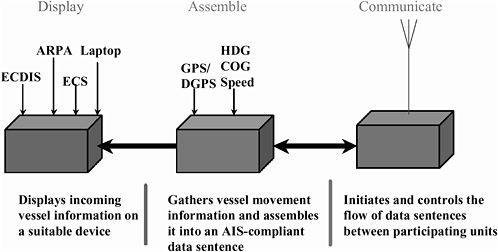
FIGURE 1-1 Elements of shipboard AIS. ARPA = automatic radar plotting aid; COG = course over ground; GPS = Global Positioning System; DGPS = Differential GPS; ECDIS = electronic charting and display information systems; ECS = electronic charting systems; HDG = heading. (Source: USCG 2001b.)
TABLE 1-1 Applicable International AIS Standards
|
Standard |
Organization That Issued the Standard |
Issue Date |
|
Functionality |
International Maritime Organization, MSC 74(69) |
May 1996 |
|
Technical |
International Telecommunication Union, ITU-R M.1371 |
November 1998 |
|
Certification |
International Electrotechnical Commission, IEC 61933-2 |
February 2002 |
|
Applicability |
International Maritime Organization, SOLAS Chapter V |
December 2000 |
|
Compliancea |
International Maritime Organization, SOLAS Chapter V |
July 2002 to July 2006 |
|
Communications |
Channel 87B / 88B—World Radio Conference, ITU-A S18 |
May 1997 |
|
a“Compliance” may be interpreted as the “requirement to carry and use.” Sources: USCG 2001a; IMO 2001a; IMO 2001b. |
||
equipment test standards. They are summarized in Table 1-1. The three key standards are identified below:
-
IMO Resolution MSC.74(69), Annex 3, Recommendation on Performance Standards for a Universal Shipborne Automatic Identification System (AIS) (IMO 2002b): This standard defines the basic performance requirements for AIS equipment and was used by ITU and the International Electrotechnical Commission (IEC)8 in developing technical and test standards.
-
ITU-R Recommendation M.1371-1, Technical Characteristics for a Universal Shipborne Automatic Identification System Using Time Division Multiple Access in the Maritime Mobile Band (ITU 2001): This standard defines in detail how the AIS works and is the primary AIS standard. The ITU Sector for Radiocommunications formally adopted this standard in August 2001 and gave to the International Association of Aids to Navigation and Lighthouse Authorities (IALA) the responsibility of maintaining technical guidelines for AIS design.
-
IEC 61993-2 Ed.1, Maritime Navigation and Radiocommunication Requirements—Automatic Identification Systems (AIS)—Part 2: Class A Shipborne Equipment of the Universal Automatic Identification System (AIS)—
-
Operational and Performance Requirements, Methods of Test and Required Test Results (IEC 2001): This standard defines the certification test requirements for Class A shipborne AIS equipment. IEC formally adopted this standard in November 2001.
In addition to the international performance and technical requirements shown in Table 1-1, the United States has established certain specific standards of its own. They are shown in Table 1-2. These standards are still evolving and, to date, do not cover any shipboard display issues.
Ship-Originated AIS Messages
AIS messages need to be updated and retransmitted every few seconds because the usefulness of some data, particularly data applying to the position and movement of vessels, decays rapidly as a function of time. For vessel position and movement data to be useful, the update rate must be sufficient to develop a cohesive representation of the transmitting vessel’s position and track. In the case of vessels operating at higher speeds or maneuvering, the data must be refreshed more often. In consideration of this, the standards provide for updates that vary with the transmitting vessel’s movements. Typical vessel movement conditions and the corresponding reporting intervals are shown in Table 1-3.
TABLE 1-2 Applicable U.S. AIS Standards
|
Standard |
Organization That Issued the Standard |
Issue Date |
|
Certification |
U.S. Coast Guard, 46 CFR 159 |
December 2001 |
|
Applicability |
U.S. Coast Guard, 33 CFR 164.43 |
July 2001 |
|
Compliance |
U.S. Coast Guard, 33 CFR 161 |
July 2001 |
|
Communications |
Channel 228—Federal Communications Commission, 47 CFR 80.371(3) |
July 1996 |
|
|
Channel 87—U.S. Coast Guard, Memorandum of Understanding |
March 2001 |
|
|
Channel 288—National Telecommunications Information Agency |
July 2001 |
|
Source: USCG 2001a. |
||
TABLE 1-3 Vessel-Transmitted AIS Update Rates
|
Ship’s Maneuvering Condition |
Nominal Reporting Interval |
|
At anchor or moored and not moving at more than 3 knots |
3 minutes |
|
At anchor or moored and moving at more than 3 knots |
10 seconds |
|
Under way, moving at 0–14 knots |
10 seconds |
|
Under way, moving at 0–14 knots and changing course |
3.3 seconds |
|
Under way, moving at 14–23 knots |
6 seconds |
|
Under way, moving at 14–23 knots and changing course |
2 seconds |
|
Under way, moving at more than 23 knots |
2 seconds |
|
Under way, moving at more than 23 knots and changing course |
2 seconds |
|
Sources: IMO 2001a; IALA 2001, Table 2-1. |
|
Table 1-4 identifies vessel-originated AIS data and their source under three general headings: static, dynamic, and voyage-related. For oceangoing vessels, static data are pertinent to the particular vessel and typically would not change from voyage to voyage. However, static data for inland tows would change frequently. Voyage-related data change each time the vessel prepares to depart for another port. Dynamic data change from second to second as the vessel makes its way to its destination. In addition to these required data, discretionary data may be transmitted as desired by the vessel master, and optional data may be transmitted if appropriate sensor equipment is installed and properly connected to the AIS unit for compilation into the AIS message format and timely transmission.
From the perspective of the mariner, the data conveyed by ship-to-ship AIS can provide a heightened level of awareness of other vessels and their movements in a waterway. While there is an ongoing debate about the propriety of relying on AIS for collision avoidance, it holds the promise of serving this purpose when it is fully developed. Rule 7 of the International Regulations for the Prevention of Collisions at Sea states: “Every vessel shall use all available means appropriate to the prevailing circumstances and conditions to determine if risk of collision exists. If there is any doubt such risk shall be deemed to exist.” Thus, it seems logical that AIS will, with the impo-
TABLE 1-4 Vessel-Originated AIS Data (Required, Discretionary, and Optional)
|
Data |
Data Source |
|
Static information: Every 6 minutes and on request of competent authority |
|
|
Vessel name |
Set on installation |
|
Call sign/mobile maritime service identity (for VHF DSC–equipped vessels only) |
Set on installation |
|
Length and beam |
Set on installation |
|
Type of ship |
Set on installation from preinstalled list |
|
IMO number |
Set on installation |
|
GPS antenna location |
Set on installation |
|
Height over keel |
Set on installation |
|
Dynamic information: Dependent on speed (see IALA 2001, Table 1-1) |
|
|
Ship position with accuracy indication and integrity |
Automatic update from position course sensor Accuracy indication better or worse than 10 meters |
|
Position time stamp |
Automatically updated from main position sensor |
|
Course over ground |
Automatically updated from main position sensor |
|
Speed over ground |
Automatically updated from main position sensor |
|
Heading |
Automatically updated from main position sensor |
|
Navigational status |
Manually entered by the officer of the watch Under way by engine At anchor Not under command Restricted in ability to maneuver Moored Constrained by draft Aground Engaged in fishing Under way by sail |
|
Rate of turn (ROT) |
Automatically updated from ship’s ROT sensor or derived from gyrocompass |
|
Note: Provisions are made for input from external sensors of additional information where available (angle of heel, pitch, roll, etc.). |
|
|
Data |
Data Source |
|
Voyage-related information: Every 6 seconds, when data amended or on request |
|
|
Ship’s draft |
Entered at start of voyage, updated as required |
|
Hazardous cargo (type) |
Entered at start of voyage |
|
Destination and estimated time of arrival |
Entered at start of voyage, updated as required |
|
Route plan |
Entered at start of voyage, updated as required |
|
Number of persons on board |
Includes crew; entered at start of voyage |
|
Short safety-related messages: As required |
|
|
Free format short text messages manually entered as required |
|
|
Note: DSC = digital selective calling. Sources: IMO 2001a; IALA 2001, Table 3-1. |
|
sition of carriage requirements, be one of the “available means.” In fact, AIS overcomes two important limitations of radar when that sensor is used for collision avoidance: (a) the raw radar echo targets do not normally represent the real dimensions of a target, and (b) significant delays occur in providing a true representation of a turning target.9 The data must be properly displayed if AIS is to adequately support navigation.
When AIS is called on to serve a function such as collision avoidance, shipboard display becomes critical. The display of ship-to-ship data, specifically the dynamic data that deal with vessel movement, has developed faster than the display of other types of data. For example, IMO Resolution MSC.74(69), Annex 3 (AIS) (IMO 2002b), Paragraph 6 specifies that the minimum information to be displayed will consist of
-
Position,
-
Course over ground,
|
9 |
For a detailed discussion of these radar limitations, see Chapter 4 of the IALA Guidelines (IALA 2001). |
-
Speed over ground,
-
Heading, and
-
Rate of turn or direction of turn as available.
IMO (2001b) has published recommended standards for the display of ship-to-ship data, including the symbology that should be used to display vessel targets.10 The display of shipboard AIS information is the subject of this report.
Shore-Originated AIS Messages
Shore-originated AIS messages can encompass a broad range of subjects:
-
Information about aids to navigation, including such details as whether they are working properly and environmental conditions at an aid’s station;
-
Meteorological or hydrological data;
-
Information about pseudoaids to navigation, providing the location and identification of specific geographic reference points;
-
The identity, position, and dimensions of offshore structures;
-
VTS waypoints or route plans used by a VTS to advise ships of the waypoints or route to be used. Such plans may consist of up to 12 waypoints or a route specified by a textual description. If waypoints are transmitted, a recommended turning radius can be included for each one; and
-
Shore-based radar target information from a vessel traffic center. The radar images would be converted and retransmitted to AIS-equipped vessels, where they could be displayed as pseudo-AIS targets.
In addition to the above, IALA (2001, Section 7.4) has suggested that AIS use in pilot waters can ultimately be broadened to “provide a bird’s eye view of a docking operation with tugboats connected or pushing including information such as bollard pull, direction of pull and even issuing the commands to tugboats.”
The sheer volume of the information messaging possible suggests that displays may be used for a wide variety of purposes. Displays, for example, may be considered as the means by which AIS data are converted into informa-
|
10 |
See Chapter 4, IALA Guidelines (IALA 2001). |
tion that the mariner can readily assimilate and use in decision making. For example, if the VTS waypoints/route plan are conveyed from VTS to the mariner as a series of latitude–longitude coordinates, the data must be plotted on a chart in order to be useful. If, however, the route is displayed graphically on an electronic charting system that also displays own ship and other vessel positions, it is immediately available without adding to bridge management workload. The requirements for a display are thus also dependent on what data are provided from shore. The volume of data that will be transmitted from shore affects the extent of the shore-based infrastructure. Close coordination is therefore needed between the carriage requirements for displays and the development of shore infrastructure. Standardization of what data are transmitted from shore is also critical to ensure a common operating environment between ports and regions.
IALA (2001) is considering a three-tiered structure that would provide
-
International applications controlled by IMO;
-
Regional applications controlled by organizations such as the European Union; and
-
Local applications controlled ether by national competent authorities or local groups—ports, pilot organizations, and so forth.
Such an approach, however, could significantly complicate display requirements.
CURRENT DISPLAY DESIGNS AND THEIR CAPABILITIES
Shipboard AIS displays can take many forms. Several design concepts are available and have been used in a number of applications. Portable units in the form of laptop computers employing AIS or similar transponder-based technology are now in common use by ship pilots in the St. Lawrence Seaway and in several U.S. ports such as New Orleans, Tampa, and Delaware Bay. For existing vessels, AIS displays could be either portable or fixed units and could be either separate or integrated with other displays such as electronic charts. For new vessels, the opportunity exists to design and install any number of stand-alone or integrated systems that may be part of a modern integrated bridge navigation complex.
Shipboard AIS display technologies span a significant range of sophistication, complexity, functionality, and cost. While the technologies and their application and marketing are constantly evolving, it is still worthwhile to consider the basic types of AIS display devices available and being put into service aboard ships. These devices range from the simple minimum three-line alphanumeric displays to robust integration of AIS information into electronic chart displays and radar systems. Depending on a particular vessel’s need or ability to accommodate varying levels of AIS display sophistication, the most appropriate installation can be implemented. Because the display is the primary interface between the AIS and the human operator (i.e., master, pilot, etc.), it is important to maximize the effectiveness of this information exchange. The following four general types of AIS displays are currently available:
-
MKD. This is the most elementary AIS display concept, incorporating a three-line alphanumeric display screen, typically a backlit monochrome liquid crystal display (LCD) device. Alphanumeric text conveying the basic AIS information scrolls across the display, allowing the operator to read the information. A simple keyboard or keypad is provided to allow limited operator input and control of the display device. Because it is limited to three scrolling lines of alphanumerics, this device does not lend itself to conveying the graphical images that are so often considered to possess much greater information density.
-
Iconic display. This is a relatively simple AIS display concept incorporating a display screen on which simple icons representing AIS targets are plotted. Along with the graphical representation of the vessel traffic environment, AIS information such as bearing, target angle, speed, and so forth are displayed for each icon. Although this type of display provides more information quickly to the operator than does a minimum three-line display, iconic displays are still typically monochrome, low-resolution devices. The information displayed is also a very simplified and limited representation of the actual traffic situation. Iconic displays are only capable of displaying dedicated AIS information and thereby serve only a single bridge function.
-
Computer display. A more sophisticated AIS display concept uses a full-color, high-resolution computer display screen. These screens provide the benefits of bright vibrant color, excellent resolution, large size,
-
and good contrast and can be traditional cathode ray tubes, plasma screens, or LCD flat panels. They can even be projection devices, in theory. Desktop personal computers, laptops, or notebook computers typically included in carry-aboard AIS pilot packs use these display devices and include full keyboards for data entry. A possible variation on this concept includes use of handheld computing devices with built-in display screens. Computer devices are typically adjustable for color, brightness, contrast, and other attributes and can easily be adapted to service in various ambient conditions, from bright sunlight to fluorescent work light to night darkness.
-
Electronic charting systems (ECS)/electronic charting and display information systems/radar/automatic radar plotting aid integration. Arguably the most sophisticated AIS display technology today involves the integration of AIS information with other bridge navigation and information systems, such as ECS and radar. Through the use of dedicated display devices intended for ECS, radar, or other established purposes, AIS information can be provided to the operator in the form of complex iconic plots representing each AIS target and associated details of the target, such as bearing, heading, and speed. Successful integration with an accurate electronic chart could allow for increases in the value of AIS information for navigation and safety purposes. However, many technical, logistical, political, and psychological issues related to such integration of bridge equipment remain to be resolved.
STATUS OF U.S. AND INTERNATIONAL IMPLEMENTATION OF AIS
Carriage Requirements
The 2000 Amendment to Chapter 5 of SOLAS, as amended at IMO’s Diplomatic Conference of December 2002, requires that AIS be fitted aboard all ships subject to the convention and of 300 gross tons (GT) and upwards engaged on international voyages, cargo ships of 500 GT and upwards not engaged on international voyages, and passenger ships irrespective of size built on or after July 1, 2002. Cargo ships of 500 GT and upwards not engaged on international voyages must fit AIS not later than July 1, 2008. The implementation schedule is as follows:
-
Passenger ships: not later than July 1, 2003;
-
Tankers: not later than the first survey for safety equipment on or after July 1, 2003; and
-
Ships, other than passenger ships and tankers, of 300 GT and upwards but less than 50,000 GT: not later than the first safety equipment survey after July 1, 2004, or by December 31, 2004.
U.S. rulemaking to implement the SOLAS requirements and perhaps extend carriage requirements to other vessels not affected by SOLAS is under development. The specific form and implementation schedule may reflect requirements of the Department of Homeland Security, particularly the provisions of the Maritime Security Act of 2002. In general, however, it appears that certain vessels not covered by SOLAS will be among those required to carry some form of AIS in the future and will be those subject to the Bridge-to-Bridge Radiotelephone Act.
In December 2002, the U.S. St. Lawrence Seaway Development Corporation and the Canadian St. Lawrence Seaway Management Corporation, in cooperation with the U.S. Coast Guard (USCG) and the Canadian Coast Guard, issued a mandatory AIS carriage requirement for all oceangoing and lake vessels transiting the seaway beginning March 25, 2003. The seaway authorities are arranging for vendors to rent or lease AIS units to vessels without permanent AIS equipment that transit the seaway after March 25, 2003.
Long-Range AIS
In January 2002 the United States proposed to IMO that the implementation of AIS be accelerated and that means be developed to extend its range to 200 miles (IMO 2002a). In February 2002 the Maritime Safety Committee (MSC) Intersessional Working Group on Maritime Security agreed to recommend acceptance of the proposed revision to the May 2002 meeting of the committee (MSC 75) (IMO 2002a). The final decision was made by a Diplomatic Conference on Maritime Security in December 2002.11 It is by no means certain that technical and schedule changes will be adopted, and the changes necessary to extend AIS range may take significantly more time than now envisioned. International acceptance of such an application, while by
no means assured, is supported by many coastal states with related interests.12 In its submission to IMO, the United States suggested that other long-range communication systems such as International Maritime Satellite might be better used for this purpose than AIS (IMO 2002a).
There is no IMO requirement that addresses communications systems for long-range applications for AIS Class A mobile systems (IALA 2001, Chapter 20). In principle, any long-range communications system can be used if it is suitable for data transmission. Using existing onboard high-frequency and satellite-based communications systems may prove difficult because of the problems associated with connecting the AIS unit to alternate communication systems. The physical connection, testing, and fail-safe changeover from the AIS’s VHF connection to another (or parallel) system on entering the United States exclusive economic zone (EEZ)13 may not prove reliable. As newer systems are deployed (e.g., low-earth-orbit satellite transceivers), planning may enable AIS-compatible preinstalled connectors and appropriate software applications to manage the interface and transmission of AIS data over long-range systems. Except as it may affect the overall AIS implementation schedule, the long-range application of AIS for security purposes should not affect shipboard display issues.
Long-range AIS communications are based on an interrogation–response system that effectively limits the ship-related data transmitted to one or more of three “long-range data formats” shown in Table 1-5. It should be noted that the long-range queries and responses are designed for automatic handling involving no additional workload for shipboard personnel.
Development of AIS for Non-SOLAS Vessels
Several nations, including the United States, are planning to extend AIS implementation to vessels not covered by the current SOLAS requirements discussed above. Vessels affected would range from those used in a harbor
TABLE 1-5 Long-Range Data Formats
environment (tugs, pilot vessels, service vessels, etc.) to those used on the high seas, such as small commercial vessels, fishing vessels, and pleasure craft. All inland navigation vessels are also potential users of AIS. Within ITU, two classes of AIS have received the most attention and discussion: Class A systems designated for vessels under the SOLAS regulations, and Class B systems to be designated for non-SOLAS vessels.14 These two classes are described by ITU (2001) as follows:
Class A Shipborne Mobile Equipment will comply with relevant IMO AIS carriage requirements.
Class B Shipborne Mobile Equipment will provide facilities not necessarily in full accordance with IMO AIS carriage requirements.
In general, the Class B AIS designated for non-SOLAS vessels differs from the Class A system in the following ways:
-
It has a reporting rate less than a Class A (e.g., every 30 seconds at speeds under 14 knots, as opposed to every 10 seconds for Class A).
-
It does not transmit the vessel’s IMO number or call sign.
-
It does not transmit estimated time of arrival or destination.
-
It does not transmit navigational status.
-
It is only required to receive, not transmit, text safety messages.
-
It is only required to receive, not transmit, application identifiers (binary messages).
-
It does not transmit rate-of-turn information.
-
It does not transmit maximum present static draft.
In addition to the above, a third class of units, referred to as “Class A derivatives,” is not presently dealt with in detail by any of the AIS-related documentation (IMO, ITU, IEC, IALA) but is discussed in a general way in the IALA Guidelines (IALA 2001). Class A derivatives are intended to serve particular groups of users (IALA 2001, Section 12.6). The examples described are systems of inland and coastal navigation, personal pilot units15 (PPUs), and the use of AIS in harbors for service vessels such as tugs and pilot boats. Class A derivatives are intended to have the same functionality and reporting rate as Class A stations on the VHF data link message level, but all of the mandatory components of Class A stations will not be required.
The IALA Guidelines (IALA 2001, Section 1.6) identify European plans for a Class A derivative for use on inland waterways, with particular focus on areas where there is a mix of seagoing and inland vessels. This equipment would be based on and behave like the Class A shipborne mobile equipment but fall outside the purview of SOLAS. A digital selective calling component would not be included, and there may be other as yet unspecified differences.
The use of a Class A derivative as a PPU has been discussed with two variations. In one, the unit is essentially self-contained, with its own portable AIS combined with a laptop computer as a pilot workstation. In the other, the unit is a portable laptop workstation, which connects to the pilot port connector of an onboard AIS.
In general, PPUs are self-contained and are used primarily to provide pilots with their own capability in boarding vessels not fitted with AIS. According to the IALA Guidelines (IALA 2001), it is essential that such units be fitted with a heading sensor if the pilot pack is to be used in waters requiring frequent course alterations. IALA (2001) has concluded that without a heading sensor the PPU will not provide sufficient information to other vessels in the vicinity.
The standard shipboard AIS will be fitted with a pilot/auxiliary input/output port, which will allow the pilot to plug in his or her own workstation and receive more frequent “own ship” navigational information. In this way the pilot will also receive all other AIS information at the standard AIS rate and be able to forward information to other vessels in the vicinity or to a VTS.
A PPU may also be equipped with a display capability different from that installed on the ship. This would facilitate providing pilots with waterway-specific information beyond that which might be manageable with a typical shipboard display. Such use appears to be recognized by the IALA Guidelines (IALA 2001, Section 12.6.2).
Security Issues
Security issues associated with shipboard display of AIS information were considered by the committee. One question was how security concerns might affect display requirements; another was how additional display parameters for security purposes might add to the mariners’ workload. Other security issues and the overall need to improve security in the nation’s ports and waterways are not covered in this report.
The use of AIS to provide information about vessels within national waters is an extension of AIS’s basic function to provide information to coastal states. No additional shipboard requirements will be imposed providing the data transmitted are limited to those already incorporated in the IMO requirements.
A number of past efforts have defined the need to prevent waterborne terrorism under the term maritime domain awareness (MDA). In simple terms, MDA is defined as having “effective knowledge of all activities and elements in the maritime domain that could represent threats to the safety, security or environment of the United States or its citizens” (Loy and Ross 2002). The term was used in USCG’s 1999 Strategic Plan (USCG 1999).16 The area encompassed by the “maritime domain” is considerable, consisting of the United States EEZ and, judging by recent actions [e.g., Brosnan (2002)], the nation’s inland waterways. The maritime domain thus consists of the 3.4 million square miles of the nation’s EEZ and an estimated 25,000 miles of inland waterways. There is no exact definition of MDA’s appropriate level of “effective knowledge,” but some tools include “real-time cargo, people, vessel tracking systems” (Loy 2001). The vessel-tracking requirements might encompass many types of vessels within a variety of waterway situations—most likely those regions where AIS will be used in the future. Conceptually, MDA can include surveillance, reporting of voyage/cargo/passenger/crew–related data, enforcement, data collection, and decision support.
AIS clearly supports the surveillance component, and the United States has made clear its intention to use AIS in that capacity. It is attractive for this purpose because it can piggyback on a carriage requirement that will be imposed for other reasons and because it provides a solution to U.S. inability to unilaterally require reporting of position and movement by all foreign-flag vessels operating within one of the areas of major interest, the EEZ outside U.S. territorial waters. As a surveillance tool, the basic automatic messaging will probably provide the necessary data without the requirement for additional input and without affecting the shipboard display of AIS information. The second component, reporting of voyage/ cargo/passenger/crew–related data, may fit technically within the capability of ships to transmit short safety-related messages via AIS, depending on the data requirements imposed. Until those requirements have been established with respect to both data content and frequency, the effect on mariner workload and shipboard display requirements remains a matter of
conjecture. The remaining MDA components do not appear to affect shipboard operations or displays.
In November 2002, the Maritime Transportation Security Act of 2002 was signed into law, with the following provisions dealing with AIS:
|
§ 70114. |
Automatic identification systems |
|||
|
|
(a) |
SYSTEM REQUIREMENTS.— |
||
|
|
|
(1) |
Subject to paragraph (2), the following vessels, while operating on the navigable waters of the United States, shall be equipped with and operate an automatic identification system under regulations prescribed by the Secretary:17 |
|
|
|
|
|
(A) |
A self-propelled commercial vessel of at least 65 feet overall in length. |
|
|
|
|
(B) |
A vessel carrying more than a number of passengers for hire determined by the Secretary. |
|
|
|
|
(C) |
A towing vessel of more than 26 feet overall in length and 600 horsepower. |
|
|
|
|
(D) |
Any other vessel for which the Secretary decides that an automatic identification system is necessary for the safe navigation of the vessel. |
|
|
|
(2) |
The Secretary may— |
|
|
|
|
|
(A) |
exempt a vessel from paragraph (1) if the Secretary finds that an automatic identification system is not necessary for the safe navigation of the vessel on the waters on which the vessel operates; and |
|
|
|
|
(B) |
waive the application of paragraph (1) with respect to operation of vessels on navigable waters of the United States specified by the Secretary if the Secretary finds that automatic identification systems are not needed for safe navigation on those waters. |
|
|
(b) |
REGULATIONS.—The Secretary shall prescribe regulations implementing subsection (a), including requirements for the |
||
|
|
|
operation and maintenance of the automatic identification systems required under subsection (a). |
|||
|
§ 70115. |
Long-range vessel tracking system The Secretary may develop and implement a long-range automated vessel tracking system for all vessels in United States waters that are equipped with the Global Maritime Distress and Safety System or equivalent satellite technology. The system shall be designed to provide the Secretary the capability of receiving information on vessel positions at interval positions appropriate to deter transportation security incidents. The Secretary may use existing maritime organizations to collect and monitor tracking information under the system. |
||||
|
|
(e) |
PHASE-IN OF AUTOMATIC IDENTIFICATION SYSTEM.— |
|||
|
|
|
(1) |
SCHEDULE.—Section 70114 of title 46, United States Code, as enacted by this Act, shall apply as follows: |
||
|
|
|
|
(A) |
On and after January 1, 2003, to any vessel built after that date. |
|
|
|
|
|
(B) |
On and after July 1, 2003, to any vessel built before the date referred to in subparagraph (A) that is— |
|
|
|
|
|
|
(i) |
a passenger vessel required to carry a certificate under the International Convention for the Safety of Life at Sea, 1974 (SOLAS); |
|
|
|
|
|
(ii) |
a tanker; or |
|
|
|
|
|
(iii) |
a towing vessel engaged in moving a tank vessel. |
|
|
|
|
(C) |
On and after December 31, 2004, to all other vessels built before the date referred to in subparagraph (A). |
|
The committee briefly considered the potential for use of AIS “safety-related” messaging to provide emergency notification of security-related events or instructions. Such use might require incorporating the capacity for alerting mariners to the receipt or transmission of urgent messages into shipboard AIS displays. Such an alerting capability may have wider application than just security.
APPROACH
This report provides a critical examination of the technical and human factors aspects of shipboard display of AIS information. This examination has resulted in recommendations that USCG can use in the development of domestic requirements and in its participation in international rulemaking and standards development.
In conducting its examination, the committee considered the following factors and prepared analyses or evaluations of each:
-
Evolving technology, security, economics, operational considerations, and human factors design principles will all affect the display of shipboard AIS. The technologies that have been used in early stages of AIS development aboard vessels as well as related systems in use in other fields, such as aviation, were reviewed; and data about vessel operational situations were obtained from numerous presentations, field visits, and vessel transits. This information is presented in Chapter 2 on operational environments and in Chapter 5, where the application of human factors principles to display design is described.
-
The impact of differing operational environments is presented in Chapter 2, and skill requirements of operators who will use the AIS shipboard displays are described in Chapter 5. These factors should be taken into consideration early in the requirements process in order to meet operating and operator needs. Chapter 2 presents an assessment of the types of vessels that will use AIS and their operating parameters (including a description of integration with other bridge information systems), and alternative methods that might be considered when data must be collected, transmitted, and transformed are suggested.
-
How the range of tasks to be supported by AIS will drive display requirements is reviewed in Chapter 4. AIS functions and shipboard tasks should be matched to the requirements that may be established for displays, and preliminary task analyses on board vessels that might carry AIS displays were conducted to illustrate a systematic approach for setting display requirements. The requirements analysis process
-
that should be used to develop AIS display requirements is described fully in Chapter 4.
-
How changes in existing and evolving technology, equipment/technical integration, international standards harmonization requirements, manufacturers’ and standards bodies’ requirements, and economics may affect shipboard display of AIS information is also described in Chapters 2 and 5. These factors were taken into consideration by reviewing relevant U.S. and international literature; convening an AIS display workshop where designers and other technical experts, manufacturers, operators, and human factors experts were invited to make presentations and engage in discussions of key issues; visiting officials and operational sites in key foreign countries where important AIS development work has been under way; examining recent experiences from relevant domestic and international AIS programs; and reviewing reports of test and evaluation programs. A summary of the workshop can be found in Appendix A, and a summary of the site visits can be found in Appendix B.
-
Human factors considerations for AIS display systems, including the mariners themselves and their capabilities and training, are discussed in Chapter 5. The operating environments within which these systems will be used and the matching of technology with human factors requirements are included in the discussion.
As a result of its reviews, examinations, and analyses, the committee prepared findings and recommendations that address the types and organization of information important for shipboard display of AIS information. The recommendations also address the application of human factors design principles to the development of shipboard AIS displays and consider the impact of such displays on future systems and programs.
This report addresses the challenges associated with shipboard display of AIS information but does not cover the full spectrum of AIS challenges. For example, AIS is a complement to traditional navigational aids; it does not replace them, nor does it substitute for good judgment or replace the need to use all available means appropriate to the prevailing circumstances and conditions to establish vessel position. This principle is a basic tenet of this report.
REFERENCES
Abbreviations
HMSO Her Majesty’s Stationery Office
IALA International Association of Aids to Navigation and Lighthouse Authorities
IEC International Electrotechnical Commission
IMO International Maritime Organization
ITU International Telecommunication Union
NRC National Research Council
USCG U.S. Coast Guard
Brosnan, J. W. 2002. Tracking the Nation’s Barges and Towboats. Corpus Christi Caller-Times, Feb. 2.
HMSO. 1994. Safer Ships, Cleaner Seas—Report of Lord Donaldson’s Inquiry into the Prevention of Pollution from Merchant Shipping. London.
IALA. 2001. IALA Guidelines on Universal Shipborne Automatic Identification System (AIS), Version 1.0. Dec.
IEC. 2001. IEC 61993 Part 2: Universal Shipborne Automatic Identification System (AIS). Operational and Performance Requirements, Methods of Testing and Required Test Results. IEC/TC80/WG8. Geneva, Switzerland, June.
IMO. 2001a. Guidelines for the Onboard Operational Use of Shipborne Automatic Identification Systems (AIS), as amended by ITU-1371. Resolution A.917(22). London.
IMO. 2001b. Interim Guidelines for the Presentation and Displays of AIS Target Information. SN Circular 217. London.
IMO. 2002a. Maritime Safety Committee, 75th Session, Item 17. MSC 75/ISWG/5/7. London, Jan. 15.
IMO. 2002b. Resolution MSC.74(69), Annex 3 (AIS). London.
ITU. 2001. Recommendation M.1371-1: Technical Characteristics for a Universal Shipborne Automatic Identification System Using Time Division Multiple Access in the VHF Maritime Mobile Band. Aug. www.itu.int/rec/recommendation.asp?type=items&lang=e&parent=R-REC-M.1371-1-200108-I.
Loy, J. M. 2001. The AFCEA and U.S. Naval Institute Western Conference and Exposition. San Diego, Calif., Jan. 23.
Loy, J. M., and R. G. Ross. 2002. Global Trade: America’s Achilles Heel. Defense Horizons, Feb. http://www.homelandsecurity.org/journal/articles/displayarticle.asp?article+33.
NRC. 1994. Minding the Helm—Marine Navigation and Piloting. National Academy Press, Washington, D.C.
NRC. 1996. Vessel Navigation and Traffic Services for Safe and Efficient Ports and Waterways—Interim Report. National Academy Press, Washington, D.C.
NRC. 1999. Applying Advanced Information Systems to Ports and Waterways Management. National Academy Press, Washington, D.C.
United Nations. 1982. United Nations Convention on the Law of the Sea (UNLOS). Geneva, Switzerland, Dec. 10.
USCG. 1999. U.S. Coast Guard Strategic Plan 1999. Washington, D.C.
USCG. 2001a. Commercial Maritime Communication in the 21st Century. Briefing, Seattle, Wash., Oct. 10.
USCG. 2001b. www.uscg.mil/vtm.
Volpe National Transportation Systems Center. 1990. Vessel Traffic Services (VTS) Technology Survey. Contract DTRS-57-88-C-00089. Mass., June 28.
Zamora, J. M. M. 1999. Fleet Tracking and Monitoring Systems for Fishing Vessels. EEZ Technology, 4th ed. ICG Publishing, Ltd., London, pp. 191–194.


