
3
THE SPACE SHUTTLE FLIGHT SOFTWARE DEVELOPMENT PROCESS
INTRODUCTION
The Space Shuttle avionics system controls, or assists in controlling, most of the Shuttle systems including: automatic determination of the vehicle's status and operational readiness; implementation sequencing and control for the solid rocket boosters and external tank during launch and ascent; performance monitoring; digital data processing; communications and tracking; payload and system management; guidance navigation and control; and electrical power distribution for the orbiter, external tank, and solid rocket boosters.
This chapter describes the numerous parts of the complete flight software development and upgrade process. Chapter 4, Chapter 5, Chapter 6 and Chapter 7 discuss the Committee's findings and recommendations that resulted from the investigation of the complete process.
THE SOFTWARE
The software programs are written in High-order Assembly Language (HAL/S), which was developed especially for the Shuttle, and are executed on the General Purpose Computers (hereafter simply referred to as the computers or GPCs).
Two essentially independent software systems have been developed to operate the orbiter avionics system:
-
The Primary Avionics System Software (PASS) consists of application software, which performs the actual functions that are required to fly and operate the vehicle, and operating system software, which controls the computer operations and provides the facilities to ensure that the application software can execute. The operating system software is always resident. On the other hand, since the applications software is too large to fit into a computer at one time, it is divided up into separate functional overlays. The overlays are stored on Mass Memory Units and are loaded into the on-board computers as they are needed for each phase of flight (descent, orbit, and entry).
-
The Backup Flight Software (BFS) provides backup capability for the critical phases of a mission and therefore contains only the software necessary to complete ascent or entry safely, maintain vehicle control on orbit, and perform the systems management function during ascent and entry (when there is no PASS systems management). Because its functions are limited, all the BFS software can fit into a computer at the same time and need never access mass memory (although a copy of the BFS software is loaded into the mass memory unit so that another computer could take over the functions of the backup computer in case of a backup computer failure). The BFS is designed to monitor everything that PASS does during ascent and entry.
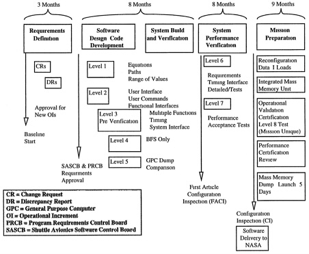
The application flight software (and occasionally system software) has to be changed as a result of changes in Shuttle hardware (including an upgrade in the computers used), detected errors, and decisions to add functionality. As stated earlier, these major updates to the software are called Operational Increments (OIs) and occur approximately once a year. As can be seen in Figure 3-1, each operational increment takes up to 28 months to develop, so the development of different operational increments proceeds in parallel.
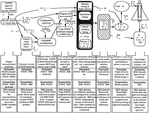
In addition to the basic software, each mission has specific requirements that relate to the activities to be carried out on that flight. The software development contractors deliver the OI base to the Space Transportation System Operations Contractor (STSOC), who configures it for the mission by adding mission-specific (payload) data, initialization data, telemetry format data, and flight software patches (corrections in response to late change requests and discrepancy reports) to produce a final integrated mass memory load.
THE PROCESS
The process for Shuttle software development and V&V is more complex than is practical to present completely here. In addition, a number of the internal processes used by the development contractors are deemed proprietary. Although the Committee was given access to much of this proprietary information, it is not appropriate for publication in this report. Instead, the Committee has included documents in Appendix D and Appendix E that provide detailed but non-proprietary information. The Committee feels it is helpful in understanding the findings and recommendations, however, to have an overall view of the process.
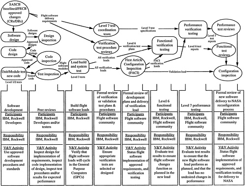
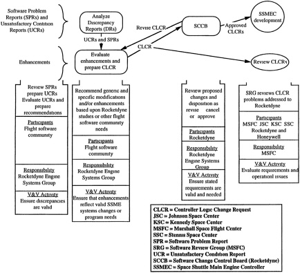
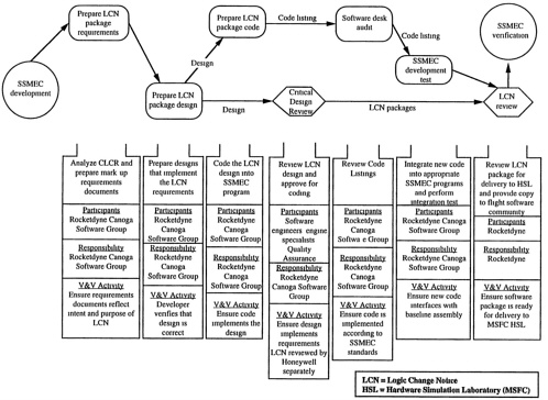
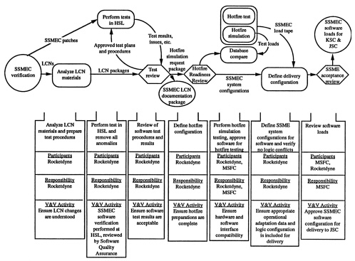
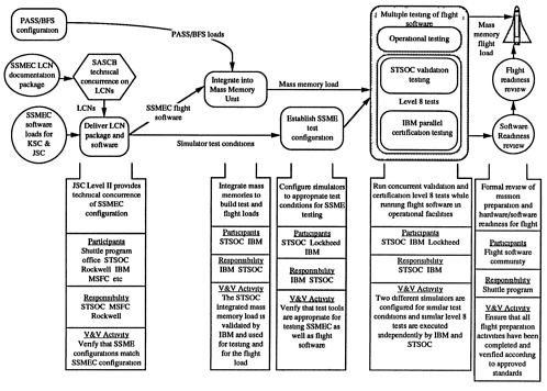
Figure 3-2a, Figure 3-2b through Figure 3-2c (Figure 5-1, Figure 5-2 through Figure 5-3 of the roadmap document included in Appendix E) show the development-process steps, and the V&V activities associated with each step, for the PASS and BFS software developed at JSC. Figure 3-3a, Figure 3-3b, Figure 3-3c, through Figure 3-3d are similar descriptions of the process steps and V&V activities for the Block 1 Space Shuttle Main Engine Controller (SSMEC) developed by the Marshall Space Flight Center (MSFC). The Block 1 SSMEC roadmap differs from the roadmap used at JSC for the PASS and BFS. In addition, there has recently been a major upgrade to the SSMEC (again developed by Rocketdyne for MSFC), called Block 2, which uses a third roadmap that is similar, but not identical, to the Block 1 roadmap. Also, each of the software development contractors (IBM, Rockwell/Downey, and Rocketdyne) have their own internal software development and V&V processes that are not shown on any of the roadmaps.

Many groups are involved in the development and V&V efforts (NASA calls this the flight software community):
-
The Space Shuttle Engineering Integration Office (by assignment to the Space Shuttle Avionics Office) has primary responsibility for the entire process of software verification and validation.
-
The Shuttle Program Office has the final authority for all flight software requirements. Within this office, the Shuttle Avionics Software Control Board (SASCB) prioritizes and evaluates all Change Requests (CRs) and Discrepancy Reports (DRs). Change packages are approved by the Program Requirements Control Board with the SASCB recommendation and then their implementation is managed by the SASCB.
-
The Mission Operations Directorate (MOD) at JSC develops the operational requirements for a Shuttle mission and uses the Shuttle Mission Simulator located at JSC for validating mission plans and procedures and to train the flight and ground crews.
-
The JSC Engineering Directorate (ED) has systems engineering responsibility for the total Shuttle hardware and software systems and evaluates the capability of each system to accomplish planned mission objectives. The JSC Flight Data Systems Division (FDSD) reviews each change in the flight software using the Software Development Facility (SDF) at JSC to perform verification tests prior to an OI release and uses the Software Production Facility (SPF) to generate and verify all patches to OIs after delivery. Engineering Directorate personnel, with support from Rockwell/Downey, use the Shuttle Avionics Integration Laboratory (SAIL) to analyze hardware and software interfaces and operations.
-
The SR&QA Office at JSC has a voting member on the SASCB (software control board) and tracks Operation Notes, User Notes, and waivers associated with flight software discrepancies. The SR&QA Office at MSFC performs a similar function for assuring the quality and safety of the SSMEC.
-
The Flight Software Development Contractors, IBM, Rockwell/Downey, and Rocketdyne, develop the PASS, BFS, and the SSMEC respectively. Within its own company, each contractor uses managerially-independent organizations, Internal IV&V, to review and examine the flight software at each stage of development. A requirements group ensures that the specified requirements are understood and that the flight software module designs incorporate the intent of these requirements. The programming group ensures that the flight software module designs are coded properly according to approved development standards. The test group verifies that the code executes properly and accomplishes the functions stated in the requirements. The build group ensures that only approved flight software modules are used in OI loads released for verification and final delivery. The SSMEC is delivered to the Shuttle Program Office at JSC as a finished package, i.e., as government furnished equipment.
-
The Flight Crew Operational Directorate (FCOD) at JSC assesses each change or discrepancy for flight safety and operational impacts using desktop review or simulators.
-
The Space Transportation System Operations Contractor (STSOC) supports JSC's MOD and Reconfiguration Management Directorate. Using government furnished equipment, flight data, and software patches from development contractors to install late corrections to fix problems documented in DRs, the STSOC reconfigures the OI loads for use on specific missions. The STSOC is currently a division of Rockwell International (and several
-
subcontractors) based in Houston, separate from the Rockwell/Downey personnel who build the BFS. The STSOC performs mission-specific tests (Level 8 testing) to verify the performance of the reconfigured system and prepares the Initialization Loads (I-Loads) 1 that are unique to each mission. Other IBM and Rockwell/Downey personnel independently build PASS/BFS software loads and perform bit-level comparisons with the newly built OI load.
-
The Systems Design Contractors, Rockwell, Lockheed, and Charles Stark Draper Labs, design tests and use the SAIL to verify that both the PASS and BFS flight software loads are compatible with hardware interfaces, perform as designed, and conform to the mission requirements. Results of each test are compared with those generated by independent offline simulations performed by the IV&V and development contractors.
Independent Verification and Validation (IV&V) is performed by Intermetrics for the PASS and BFS and by Smith Advanced Technologies for the SSMEC. The role of the IV&V contractors in assuring the software was discussed in Chapter 1, and their current functions are shown in Table 1-1 (see also Appendix D). In general, the IV&V contractor concentrates on software used during the most critical phases of flight, particularly the ascent and descent phases. The contractor typically evaluates the CRs and DRs that are submitted to cover changes in the software. However, they also often submit CRs and DRs themselves and use their specialized tools and expertise to perform a detailed evaluation of the software itself (see Appendix D for a discussion of the tools used).
|
1 |
I-Loads are a large number of data sets that contain mission parameters such as ascent and descent profiles, wind data, payload mass information, unique characteristics of the orbiter being used for a given mission, etc. These data sets are updated for each mission and are even updated on the day of launch in certain cases. They are not strictly a part of the flight software, but without this initializing data the software would not run properly. The Committee did not consider the processes by which I-Loads are determined, controlled, tested, or assured. |


