
2
Distributed Feedback Resonators
Hermann A. Haus
Massachusetts Institute of Technology
|
This paper describes the invention of distributed feedback (DFB) structures for integrated optics. The realization of complex structures was carried out in acoustics as cascades of Surface Acoustic Wave (SAW) resonators. I review their theory and describe experiments of acoustic wave resonators, using equivalent circuits as design guides. Finally, I present photonic bandgap materials intended for greater bandwidth along with numerical methods for their analysis. |
INTRODUCTION
The thrust of this conference is centered on electromagnetic and acoustic structures that are large compared with a wavelength. In addition there is the constraint of "structures that cannot be simplified because of irregularity in the structures." The following treatise fits into the general theme of structures that are large compared with a wavelength. It deviates from the constraint in its engineering approach to the analysis of the optical and acoustic structures described. Composite structures are formed from simpler components on the basis of simplified models (equivalent circuits) of the individual components. Only at the very end, when introducing photonic bandgap filters, is a full computer solution of the wave equation presented that includes coupling to radiation modes. Even here comparisons are made with the response of simple models. The author hopes that this approach will not be too foreign to the aims of the conference.
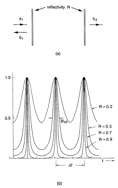
Optical resonators are generally large compared with the wavelength. A simple Fabry-Perot transmission resonator as shown in Figure 2.1, with two partially transmitting mirrors, has a resonance for every half-wavelength change of the incident radiation. If such a resonator is to be used as an optical device, the multiplicity of resonances is usually undesirable. A laser diode, which employs a Fabry-Perot formed of the cleavage planes of the semiconductor, selects one resonance frequency via the gain-bandwidth; the mode with the maximum gain oscillates and "robs" all the other modes of their gain.
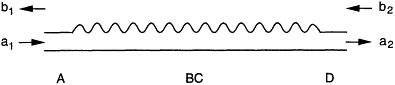
In order to make resonators and oscillators manufacturable as components in (integrated) waveguide optics, Kogelnik and Shank (1972) introduced the distributed feedback (DFB) resonator. It consists of a uniform grating, a corrugation on top of the optical waveguide, a structure that can be fabricated by photolithography and etching techniques. The waveguide contains the active medium, a heterojunction that confines the carriers which, by recombining, provide the optical gain. The same structure can be used as a transmission filter. It is to this passive realization that we shall devote our attention. The schematic of this simple grating structure is shown in Figure 2.2.
The simple DFB structure has resonances to either side of the stopband as we shall show in detail in the reflection filter section below. If used as a laser resonator, the oscillator may choose either one of the two frequencies depending upon small perturbations that break the gain degeneracy. To overcome this problem and to arrive at a structure with no gain degeneracy, in 1975, Dr. C.V. Shank, then of Bell Laboratories, and the author arrived at a resonator design, the quarter wave shifted DFB resonator with the schematic shown in Figure 2.3 (Haus and Shank, 1976). The grating consists of two sections, and at their juncture they are separated by a quarter wave gap. This gap acts like a local defect in a crystal lattice, generating a local state at the center of the stopband (bandgap). Thus the degeneracy is removed and the resonance at the center of the bandgap experiences the grating reflectivity where it is strongest, not like the uniform structure whose resonances lie outside the stopband.
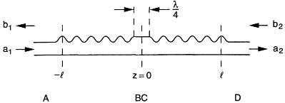
Figure 2.3 Schematic of quarter wave shifted DFB resonator.
The simple resonances of the quarter wave shifted DFB structure suggest that one may construct filter structures from cascaded resonators. The basic idea of cascading quarter wave shifted resonators for the purpose of filter synthesis was presented almost 20 years ago (Haus and Schmidt, 1977a,b). The idea was aimed at optical filter synthesis, but was applied to SAW resonators, since at that time it was not possible to fabricate optical gratings within the required tolerances. The idea was tested with Surface Acoustic Wave (SAW) filters in the 100 MHz regime in which grating groove spacings of the order of 20 microns are required, easily achievable at that time. The idea did not catch on in the SAW field, in part because the design did not use piezoelectric coupling that gives SAW design added flexibility. This advantage does not exist in optical applications, and hence it is likely that the approach will find greater acceptance in waveguide optics.
In wavelength division multiplexed optical communications it is desirable to access one of the channels from a signal bus, without affecting the other channels. Resonant coupling can be used for this purpose. Again, the quarter wave shifted DFB resonators, side-coupled to a signal bus, can accomplish this function. The section on side-coupled resonators discusses the analysis of such structures.
Thus far, we have been describing grating structures with a corrugation etched onto an optical waveguide. The reflection per grating groove tends to be small, the structures tend to be many wavelengths long, and the stopbands are correspondingly narrow. If wider stopbands are to be achieved, the photonic bandgap structures have to be used. An analytic treatment of such structures is inadequate, since they are open and prone to radiate. At MIT we are currently pursuing both the analysis and the fabrication of such structures. In the closing section on photonic bandgap crystals we shall discuss some of the issues.
THE EQUATIONS OF DISTRIBUTED FEEDBACK GRATING
A traveling wave of a single mode in an optical waveguide, of frequency ω and amplitude a, obeys the equation
where β is the propagation constant of the mode, in general a function of frequency. For narrow band signals, dispersion can be neglected and expansion around a frequency ω0 gives
where ![]() is the group velocity. The wave of amplitude β traveling in the opposite direction obeys the equation
is the group velocity. The wave of amplitude β traveling in the opposite direction obeys the equation
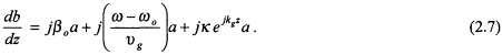
In the absence of a perturbation, in a uniform waveguide, these two waves are uncoupled. If there is a perturbation, like a local change of index, the forward wave couples to the backward wave. If the perturbation is cosinusoidal, as produced by a cosinusoidal corrugation on top of the waveguide (see Figure 2.2), the equation for a is modified. Aside from coupling to the backward mode, radiation may be produced:
For a weak perturbation, the coupling to b will be strong only when the grating is close to the Bragg condition
Figure 2.4 indicates this with a vector diagram of the wave vector of the forward wave, of the backward wave, and of the grating. Only the exp(+jkgz) component of the grating couples the forward wave to the backward wave. The coupling to radiation fields can be made negligible if
-
The vector β0 - kg lies outside the surface of wave vectors of the radiation field. In this case there is no phase match to the radiation modes.
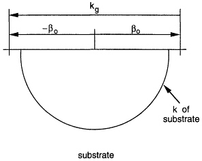
Figure 2.4 The radiation suppression condition for isotropic substrate.
-
The grating is weak, so that the spatial dependence of a deviates little from its natural exp(-jβ0z) dependence.
The conditions are generally met in integrated optics with gratings on the surface of the optical waveguide. Under these conditions (2.4) simplifies to
The coefficients in the equation for the backward wave are the complex conjugate of those for the forward wave, since it is the time reversed version of the equation for the forward wave
With the introduction of envelope variables A and B
one gets the simple coupled mode equations
where
With κ positive, one can show (Haus, 1984) that the reference planes for evaluation of A and B are picked at the maximum of the index corrugation as shown in Figure 2.2.
THE REFLECTION FILTER
A DFB structure of length ![]() acts as a filter. In this section we derive the filter response of such a structure. Consider the reflection from a structure of length
acts as a filter. In this section we derive the filter response of such a structure. Consider the reflection from a structure of length ![]() , with one end matched, B = 0 at z = 0 (Figure 2.5). For |δ| < |κ|, the solutions of (2.9) and (2.10) are of the form exp(+γz), where
, with one end matched, B = 0 at z = 0 (Figure 2.5). For |δ| < |κ|, the solutions of (2.9) and (2.10) are of the form exp(+γz), where
The solutions are growing and decaying exponentials, whereas they are periodic functions in the range |δ| < |κ|.
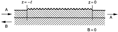
Figure 2.5 The boundary conditions on reflection filter.
The general solutions with arbitrary constants are
where only two of the four constants are independent. From (2.9) we find a relation between B± and A±:
At z = 0 there is no reflected wave, B+ = - B-, and thus
Using (2.10), we obtain for A(z)
The reflection coefficient Г = B / A at ![]() is
is
The analysis can be generalized to cover an arbitrary reflection at z = 0, Г(0). One then finds after some simple manipulation
Equation (2.17) is a special case of (2.18) with Г(0)= 0 and ![]() . Figure 2.6 shows
. Figure 2.6 shows ![]() of (2.17) as a function of δ -, the frequency parameter. The reflection coefficient is zero at a set of frequencies within the passband. At these frequencies the backward wave has a sinusoidal distribution within the structure, according to (2.15), with γ pure imaginary, and vanishes at the two end planes of the structure. These frequencies are the resonance frequencies of the periodic structure acting as a "distributed" Fabry-Perot transmission resonator. Instead of a single pair of mirrors, the periodic structure has a large number of reflecting "mirrors," one for each pair of periods of the structure lying symmetrically with respect to the center plane of the structure.
of (2.17) as a function of δ -, the frequency parameter. The reflection coefficient is zero at a set of frequencies within the passband. At these frequencies the backward wave has a sinusoidal distribution within the structure, according to (2.15), with γ pure imaginary, and vanishes at the two end planes of the structure. These frequencies are the resonance frequencies of the periodic structure acting as a "distributed" Fabry-Perot transmission resonator. Instead of a single pair of mirrors, the periodic structure has a large number of reflecting "mirrors," one for each pair of periods of the structure lying symmetrically with respect to the center plane of the structure.
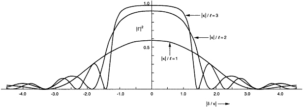
Figure 2.6 The reflection of the filter of Figure 2.5.
In Figure 2.6, |κ| is kept constant at its value for δ = 0; in other words, it is treated as if it were frequency independent (δ independent). This approximation is consistent with the approximations inherent in coupled mode theory. The two modes a and b couple within a normalized frequency range ±δ of the order of ±|κ|. A frequency dependence of |κ| can be ignored as it is of second order (i.e., equal to the product of δ and dκ / dδ).
THE QUARTER WAVE SHIFTED DFB RESONATOR
The transmission resonances of the uniform DFB structure lie to either side of the grating stopband. If an active medium in the resonator provides sufficient gain, the system oscillates at one of the transmission resonances. The resonance with highest Q is most prone to lasing (if the gain peak is close to the resonance). Thus the uniform DFB structure may lase on either of the two transmission resonances to either side of the stopband, since they possess the same Q, a Q that is larger than those of the resonances further away (as evidenced by their transmission bandwidths). Random reflections from the end of the structure favor either one or the other of the two resonances.
In order to remove this uncertainty in lasing frequency, C.V. Shank and the author proposed the quarter wave shifted resonator of Figure 2.3. This resonator has a high Q-resonance at the center of the stopband. If symmetric, it is a filter that transmits all the power at resonance. This can best be seen by a graphical construction in the complex reflection coefficient F plane, the Smith chart familiar to microwave engineers. Figure 2.7 shows the loci of the transformation of F with varying lengths of grating with a detuning such as to remain inside the stopband (Haus, 1975). There are two fixed points: these are the eigensolutions of the equations; their characteristic F does not change as one moves along the grating.
Figure 2.8 looks at the transformation at the center-frequency of the stopband. The fixed points are at ±j. If the right-hand side of the structure of Figure 2.3 sees a match, then the length ![]() of grating transforms the reflection coefficient of point A into that of point B in Figure 2.8a. The quarter wave shift transforms it into point C. Another section of grating of the same length brings the reflection coefficient back to the origin: the structure appears matched at the input plane.
of grating transforms the reflection coefficient of point A into that of point B in Figure 2.8a. The quarter wave shift transforms it into point C. Another section of grating of the same length brings the reflection coefficient back to the origin: the structure appears matched at the input plane.
When the frequency is slightly detuned, the fixed points move as shown in Figure 2.8b. The transformation proceeds as indicated, and the reflection coefficient at the input moves. If the grating structure is long, ![]() , then the Q of the structure is high and the transmission characteristic approaches that of a simple resonator; it is Lorentzian, a circle in the Г plane which closes at Г = - j as shown. This is the resonance of a parallel L-C circuit as viewed through a segment of transmission line of length λ / 8. Because the structure is symmetric, such a segment must be added to the other side as well. In the construction of Figure 2.8 this segment has no effect because we assumed a match on the right-hand end. Thus, with reference planes chosen at the peak of the index corrugation, the equivalent circuit for the center resonance of the quarter wave shifted DFB resonator is a parallel LC circuit with λ / 8 segments of transmission line added to both sides. The resonance is described by two parameters: (a) the resonance frequency (in the equivalent circuit 1/(LC)0.5, and (b) the external Q (related to Y0 / C ). The Q can be evaluated by simple perturbation theory.
, then the Q of the structure is high and the transmission characteristic approaches that of a simple resonator; it is Lorentzian, a circle in the Г plane which closes at Г = - j as shown. This is the resonance of a parallel L-C circuit as viewed through a segment of transmission line of length λ / 8. Because the structure is symmetric, such a segment must be added to the other side as well. In the construction of Figure 2.8 this segment has no effect because we assumed a match on the right-hand end. Thus, with reference planes chosen at the peak of the index corrugation, the equivalent circuit for the center resonance of the quarter wave shifted DFB resonator is a parallel LC circuit with λ / 8 segments of transmission line added to both sides. The resonance is described by two parameters: (a) the resonance frequency (in the equivalent circuit 1/(LC)0.5, and (b) the external Q (related to Y0 / C ). The Q can be evaluated by simple perturbation theory.
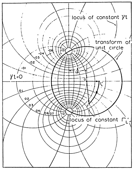
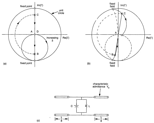
Figure 2.8 The graphical construction for quarter wave shifted resonator and its equivalent circuit: (a) at resonance, (b) slightly off resonance, and (c) equivalent circuit.
One performs the thought experiment in which one considers the resonance excited at t = 0 and one determines the power ![]() , escaping from either end of the structure, i = 1,2. The external Q of the resonator follows from the definition
, escaping from either end of the structure, i = 1,2. The external Q of the resonator follows from the definition
where W is the stored energy. The dependence upon z of A (and B) at the gap-center-frequency is exponential, A = A0 exp(± κ z), except near the ends where the structure must see a match, where either A = 0 on the left hand side, or B = 0 on the right hand side. But this means that the spatial dependence of the wave on the right-hand side near ![]() , in terms of the amplitude A0, at the center of the structure, is given by:
, in terms of the amplitude A0, at the center of the structure, is given by:
The power escaping is:
The energy is:
where one factor of 2 accounts for the energy in both A and B, and the other factor of 2 accounts for the two sides of the structure. Thus the external Q is
The external Q's of the equivalent circuit are given by
where Y0 is the characteristic admittance of the transmission line. The transmission characteristic of the quarter wave shifted resonator is as shown in Figure 2.9 for varying values of ![]() . The center resonance is Lorentzian, and its width is accurately predicted by the external Q computed above for
. The center resonance is Lorentzian, and its width is accurately predicted by the external Q computed above for ![]() . The structure is reflecting over the remainder of the stopband, gradually providing less and less reflection with increasing deviation from the stopband. There are other low Q resonances outside the stopband.
. The structure is reflecting over the remainder of the stopband, gradually providing less and less reflection with increasing deviation from the stopband. There are other low Q resonances outside the stopband.
A single grating pair gives a Lorentzian transmission characteristic near the center of the stopband. This is analogous to the equivalent circuit of Figure 2.8 which represents the quarter wave shifted resonator at and near the center resonance. It is well known that cascades of such resonators, separated by quarter wave segments of transmission line, produce very desirable filter characteristics. Since a quarter wave line inverts the impedance, a three segment structure as shown in Figure 2.10 has the equivalent lumped circuit as shown. If one varies the circuits in the cascade, various filter characteristics can be achieved. One can take advantage of handbook information on filter design and end up with Chebysheff, Butterworth, or Gaussian filters as shown in Figure 2.11. These are formed of resonant circuits with the same resonance frequency but with different L/C ratios. The relation for the external Q's relates the grating lengths to the normalized capacitance C/Y0 of the equivalent circuit.
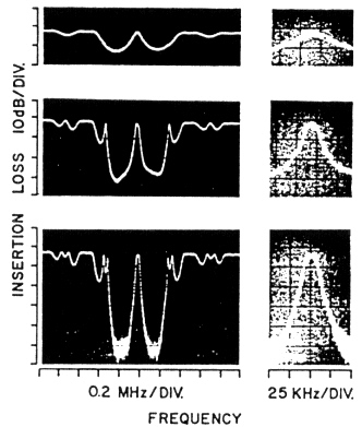
In 1976 we realized some of these circuits with SAW filters (Haus and Schmidt, 1977a). Figure 2.12 shows some experimental results with SAW resonators, the three figures corresponding to one, two, and three resonators in cascade. One can see the excellent agreement of the experimental transmission characteristic with the theoretically predicted one in Figure 2.11a down to a - 60 dB level.
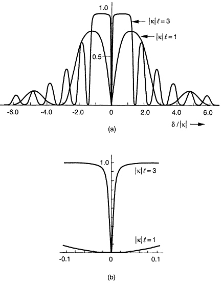
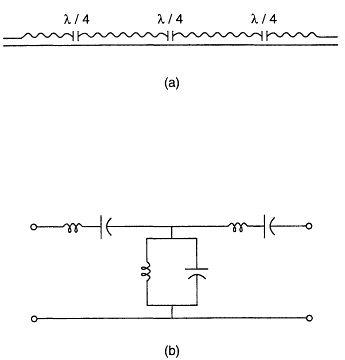
Figure 2.10 Three quarter wave shifted DFB resonators (a) in cascade and (b) their equivalent circuit.
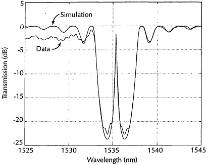
Recently, in the Nanostructure Laboratory, in cooperation with Professor H. I. Smith and his students, we started fabricating quarter wave shifted DFB structures for optical filters centered at a wavelength of 1.54 microns, the wavelength of erbium amplifiers and of long distance optical communications. Figure 2.13 shows the experimentally observed response and the theoretical fit to it. The transmission at resonance is lower than predicted. This may be due to experimental resolution or due to radiation losses. This point needs further investigation. Otherwise, the agreement is excellent except for the deviation on the short wavelength side of the response. It is here that the structure experiences radiative loss by virtue of the fact that, for a constant grating vector kg and for increasing propagation vectors β0, the spatial spectrum starts to extend into the radiation sphere of the substrate (see Figure 2.4).

SIDE-COUPLED RESONATORS
When a microwave cavity is coupled to a waveguide via a small hole, the structure is known as a Q-meter. At the resonance of the cavity, transmission in the waveguide is interrupted. This is a means for frequency calibration.
The quarter wave shifted DFB resonators side-coupled to a signal waveguide also tap off the optical power at the resonance frequency of the resonator. If the power in the resonator is detected, a channel dropping filter is realized, leaving other signals at frequencies in the stopband of the grating essentially unaffected (Haus and Lai, 1991, 1992). Figure 2.14a shows a side-coupled quarterwave shifted DFB resonator and Figure 2.14b shows its equivalent circuit at and near resonance. The equivalent circuit follows from the response of the system obtained by coupled mode analysis, expanded in frequency around resonance.
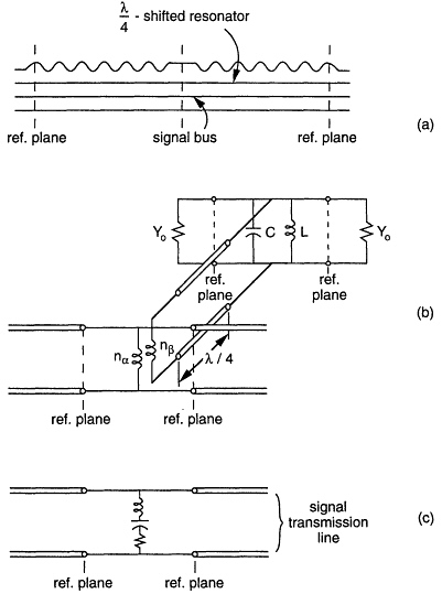
Figure 2.14 (a) Side-coupled quarter wave shifted DFB resonator, (b) its equivalent circuit, and (c) its equivalent circuit at resonance.
The parameters of the circuit follow from a simple analysis that determines the external Q of the resonator and that of the equivalent circuit. We suppose that all resonators are ''long'' enough so that the escape of power from their two ports is negligible compared with the coupling of power into the signal bus. Again we may resort to an analysis of Q's to get the equivalent circuit parameters. The coupled mode equations are
where η is the coupling from the resonator to the signal bus. If this coupling is weak, then the resonator at resonance still supports waves decaying away from the quarter wave sections. Equation (2.27) can be used to evaluate the wave excited in the signal bus from the resonator. It is easily found to be
Thus, the power escaping in the bus is
The external Q's are
We see that the equivalent L's and C's are
The power coupled to the bus is much larger than that out of the resonators if
The equivalent circuit at and near resonance is shown in Figure 2.14. At resonance, a single resonator couples out at most half of the incident power. If one wants to couple out all of the power at resonance,
one must use two resonators in cascade, the second resonator acting as a blocking circuit. This is shown in Figure 2.15. Figure 2.16 shows the transmission characteristics for single- and two-resonator arrangements using the full coupled mode analysis of (2.5)-(2.8).
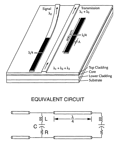
Figure 2.15 Two-resonator arrangement for full outcoupling at resonance.
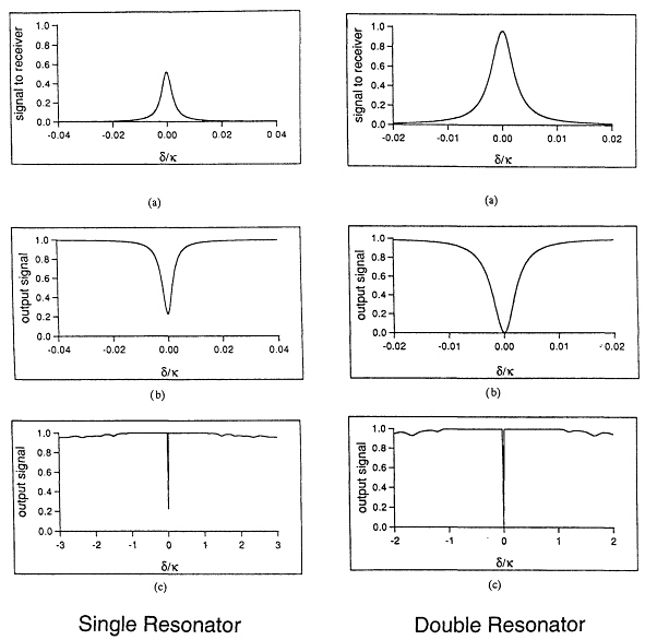
Figure 2.16 The responses of single- and double-resonator channel dropping filters.
PHOTONIC BANDGAP CRYSTALS
In recent years, photonic bandgap crystals have received a great deal of attention (Meade et al., 1991a,b, 1992, 1993a,b). One of the purposes of designing a structure which exhibits a gap for all electromagnetic waves is to construct a localized "state," i.e., a localized resonance. If gain is provided, the spontaneous emission couples only into this single resonance, providing lasing action with very special quantum properties.
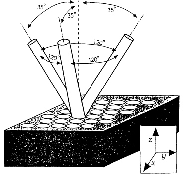
Figure 2.17 The construction of Yablonovite.
A structure proposed by E. Yablonovitch now goes under name of Yablonovite (Yablonovitch, 1987; Yablonovitch and Gmitter, 1989; Yablonovitch et al., 1991a,b). It can be constructed by drilling holes along the three axes of the diamond lattice as shown in Figure 2.17. The holes must be ½γ apart as measured in terms of the medium wavelength.
Photonic bandgap structures can only be realized with large reflection within each cell of the structure. This makes them interesting for broadband filter design along the lines of DFB filters described earlier. Modem optical communications utilizing the whole bandwidth offered by erbium doped fiber amplifiers require bandwidths, and thus stopbands, of the order of 5 THz.
For filter design it may not be necessary to use three-dimensional photonic bandgap structures. Figure 2.18 shows the kind of structure we are currently investigating for use as a quarterwave shifted DFB filter. Because the resonant mode is only a few wavelengths long, radiation becomes an important issue. Figure 2.4 shows the vector diagram for prevention of radiation-used single wave vectors. When the decay of the mode in the structure becomes large, the wave vector expands into a band of wave vectors, part of which may lie inside the radiation "sphere."
We calculate reflection, transmission, and radiation using a scalar finite difference time domain (FDTD) program (Chen, 1994) with first and second order absorbing boundary conditions (Enquist and Majda, 1977).
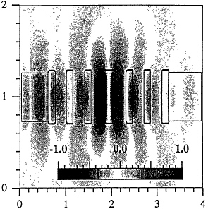
Figure 2.18 A filter structure with large reflection per cell and the field intensity distribution.
The transverse profile of the source is the fundamental mode of the waveguide; temporally, the source is a monochromatic sine wave. The field E is explicitly stepped forward in time until steady state is reached. From the field values at two different positions and times, we separate out the forward and backward propagating wave components. Taking the ratios of various field components before and after the filter gives the reflection and transmission coefficients. The radiation power is defined as the power not transmitted or reflected. This includes the power transferred to higher order transverse modes and to the substrate.
One promising filter is a more deeply etched version of the periodically segmented waveguide (Weissman and Hardy, 1993). Figure 2.18 shows a color contour plot of electric field overlaid on a contour plot of the index. The field comes in from the left side and becomes more localized about the center post. The extra thickness of this post acts as the quarter wave phase shift that produces the transmission resonance. Specifically, the posts are 0.58 by 0.14 wavelengths and have indices of n = 1.88. The air gap between adjacent posts is 0.2544 wavelengths and the center post is 0.2776 wavelengths wide. The entire device is less than 3 wavelengths long.
Figure 2.19 plots the reflection, transmission, and radiation powers as a function of normalized frequency. A large stopband, where transmitted power is zero, exists between 0.82 and 1.24. Large transmission occurs near frequencies of 0.68. Currently, we are trying to enhance the size of the transmission resonance within the stopband. We need to work more on coupling the power to the filter; much is reflected or radiated. In addition, narrower transmission resonances are expected by using even higher index contrasts.
The analysis of such structures is in its early stages and so is their fabrication. In order to diminish the radiation, the structure must be surrounded by air. Filters would have to be fabricated in the form of bridges between the input and the output. At MIT, Professor L. Kolodziejski has successfully etched bridge structures of this type. Only the future will tell whether these filters will be designable and manufacturable for the specifications of broad-band optical communication networks.
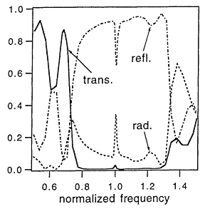
Figure 2.19 The transmission characteristic of the structure of Figure 2.18.
References
Chen, J.C., 1994, in Proceedings of the 1994 M.I.T. Student Workshopon Scalable Computing, Cape Cod, Mass .
Enquist, B., and A. Majda, 1977, "Absorbing boundary conditions for the numerical simulation of waves,"Math. Comput.31, 629-651.
Haus, H.A., 1975, "Grating filter transformation chart,"Electron.Lett.11, 553-554.
Haus, H.A., 1984, Waves and Fields in Optoelectronics, Englewood Cliffs, N.J.: Prentice-Hall, Inc.
Haus, H.A., and C.V. Shank, 1976, "Antisymmetric taper of distributed feedback lasers,"IEEE J. Quant. Electron.QE-12, 532-539.
Haus, H.A., and R.V. Schmidt, 1977a, "Transmission response of cascaded gratings,"IEEE Trans. Sonics Ultrason.SU-24, 94-101.
Haus, H.A., and R.V. Schmidt, 1977b, "Cascaded SAW gratings as passband filters,"Electron. Lett.13, 445-446.
Haus, H.A., and Y. Lai, 1991, "Narrow-band distributed feedback reflector design,"J. Lightwave Technol.9, 754-760.
Haus, H.A., and Y. Lai, 1992, "Narrow-band channel-dropping filter,"J. Lightwave Technol.10, 57-62.
Kogelnik, H., and C.V. Shank, 1972, "Coupled-wave theory of distributed feedback lasers,"J. Appl. Phys.43, 2328-2335.
Meade, R.D., K.D. Brommer, A.M. Rappe, and J.D. Joannopoulos, 1991a, "Electromagnetic Bloch waves at the surface of a photonic crystal,"Phys. Rev.B 44(19), 10961-10964.
Meade, R.D., K.D. Brommer, A.M. Rappe, and J.D. Joannopoulos, 1991b, "Photonic bound states in periodic dielectric materials,"Phys. Rev .B 44(24), 13772-13774.
Meade, R.D., K.D. Brommer, A.M. Rappe, and J.D. Joannopoulos, 1992, "Existence of a photonic band gap in two dimensions,"Appl. Phys.Lett.61, 495.
Meade, R.D., K.D. Brommer, A.M. Rappe, J.D. Joannopoulos, and O.L. Alerhand, 1993a, "Accurate theoretical analysis of photonic band gap materials,"Phys. Rev.B 48, 8434.
Meade, R.D., O.L. Alerhand, and J.D. Joannopoulos, 1993b, Handbookof Photonic Band Gap Materials, New York: JAMtex I.T.R.
Weissman, Z., and A. Hardy, 1993, "Modes of periodically segmented waveguides,"J. Lightwave Technol.11, 1831-1838.
Yablonovitch, E., 1987, "Inhibited spontaneous emission in solid state physics and electronics,"Phys. Rev. Lett.58, 2059.
Yablonovitch, E., and T.J. Gmitter, 1989, "Photonic band structures: the face-centered cubic case,"Phys. Rev. Lett.63, 1950.
Yablonovitch, E., T.J. Gmitter, and K.M. Leung, 1991a, "Photonic band structures: the face-centered cubic case employing non-spherical atoms,"Phys. Rev. Lett.67, 2295.
Yablonovitch, E., T.J. Gmitter, R.D. Meade, K.D. Brommer, A.M. Rappe, and J.D. Joannopoulos, 1991b, "Donor and acceptor modes in photonic band structure,"Phys. Rev. Lett.67, 3380.


